parking sensors JEEP CHEROKEE 2019 Owner handbook (in English)
[x] Cancel search | Manufacturer: JEEP, Model Year: 2019, Model line: CHEROKEE, Model: JEEP CHEROKEE 2019Pages: 344, PDF Size: 6.35 MB
Page 90 of 344
• Vehicle is shifted to PARK.
Disabling SSC
SSC will deactivate and be disabled if any of
the following conditions occur:
• The driver pushes the SSC switch.
• The driveline is shifted out of 4WD Low
Range.
• The parking brake is applied.
• Driver door opens.
• The vehicle is driven greater than 20 mph
(32 km/h) for greater than 70 seconds.
• The vehicle is driven greater than 40 mph
(64 km/h) (SSC exits immediately).
Feedback To The Driver:
The instrument cluster has an SSC icon and
the SSC switch has an LED which offer feed-
back to the driver about the state SSC is in.
• The cluster icon and switch lamp will illu-
minate and remain on solid when SSC is
enabled or activated. This is the normal
operating condition for SSC.• The cluster icon and switch lamp will flash
for several seconds then extinguish when
the driver pushes the SSC switch but en-
able conditions are not met.
• The cluster icon and switch lamp will flash
for several seconds then extinguish when
SSC disables due to excess speed.
• The cluster icon and switch lamp will flash
then extinguish when SSC deactivates due
to overheated brakes.
WARNING!
SSC is only intended to assist the driver in
controlling vehicle speed when driving in
off road conditions. The driver must re-
main attentive to the driving conditions
and is responsible for maintaining a safe
vehicle speed.
AUXILIARY DRIVING
SYSTEMS
Blind Spot Monitoring (BSM) — If
Equipped
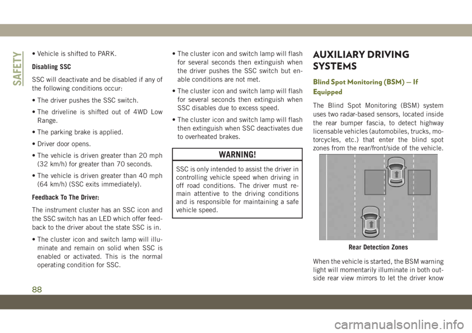
The Blind Spot Monitoring (BSM) system
uses two radar-based sensors, located inside
the rear bumper fascia, to detect highway
licensable vehicles (automobiles, trucks, mo-
torcycles, etc.) that enter the blind spot
zones from the rear/front/side of the vehicle.
When the vehicle is started, the BSM warning
light will momentarily illuminate in both out-
side rear view mirrors to let the driver know
Rear Detection Zones
SAFETY
88
Page 92 of 344
Entering From The Rear
Vehicles that come up from behind your ve-
hicle on either side and enter the rear detec-
tion zone with a relative speed of less than
30 mph (48 km/h).
Overtaking Traffic
If you pass another vehicle slowly with a
relative speed less than 15 mph (24 km/h)
and the vehicle remains in the blind spot for
approximately 1.5 seconds, the warning light
will be illuminated. If the difference in speed
between the two vehicles is greater than
15 mph (24 km/h), the warning light will not
illuminate.
The BSM system is designed not to issue an
alert on stationary objects such as guardrails,
posts, walls, foliage, berms, etc. However,
occasionally the system may alert on such
objects. This is normal operation and your
vehicle does not require service.
The BSM system will not alert you of objects
that are traveling in the opposite direction of
the vehicle in adjacent lanes.WARNING!
The Blind Spot Monitoring system is only
an aid to help detect objects in the blind
spot zones. The BSM system is not de-
signed to detect pedestrians, bicyclists, or
animals. Even if your vehicle is equipped
with the BSM system, always check your
vehicle’s mirrors, glance over your shoul-
der, and use your turn signal before chang-
ing lanes. Failure to do so can result in
serious injury or death.
Rear Cross Path (RCP)
The Rear Cross Path (RCP) feature is in-
tended to aid the driver when backing out of
parking spaces where their vision of oncom-
ing vehicles may be blocked. Proceed slowly
and cautiously out of the parking space until
the rear end of the vehicle is exposed. The
RCP system will then have a clear view of the
cross traffic and if an oncoming vehicle is
detected, alert the driver.
RCP monitors the rear detection zones on
both sides of the vehicle, for objects that are
moving toward the side of the vehicle with a
minimum speed of approximately 3 mph(5 km/h), to objects moving a maximum of
approximately 20 mph (32 km/h), such as in
parking lot situations.
NOTE:
In a parking lot situation, oncoming vehicles
can be obscured by vehicles parked on either
side. If the sensors are blocked by other
structures or vehicles, the system will not be
able to alert the driver.
When RCP is on and the vehicle is in RE-
VERSE, the driver is alerted using both the
visual and audible alarms, including reduc-
ing the radio volume.
WARNING!
Rear Cross Path Detection (RCP) is not a
back up aid system. It is intended to be
used to help a driver detect an oncoming
vehicle in a parking lot situation. Drivers
must be careful when backing up, even
when using RCP. Always check carefully
behind your vehicle, look behind you, and
be sure to check for pedestrians, animals,
SAFETY
90
Page 168 of 344
Setting The Following Distance In ACC
The specified following distance for ACC can
be set by varying the distance setting be-
tween four bars (longest), three bars (long),
two bars (medium) and one bar (short). Using
this distance setting and the vehicle speed,
ACC calculates and sets the distance to the
vehicle ahead. This distance setting appears
in the instrument cluster display.
To increase the distance setting, push the
Distance Setting — Increase button and re-
lease. Each time the button is pushed, the
distance setting increases by one bar (longer).
To decrease the distance setting, push the
Distance Setting — Decrease button and
release. Each time the button is pushed, the
distance setting decreases by one bar
(shorter).
PARKSENSE REAR PARK
ASSIST — IF EQUIPPED
The ParkSense Rear Park Assist system pro-
vides visual and audible indications of the
distance between the rear fascia and a de-
tected obstacle when backing up, e.g. duringa parking maneuver. If your vehicle is
equipped with an automatic transmission,
the vehicle brakes may be automatically ap-
plied and released when performing a reverse
parking maneuver if the system detects a
possible collision with an obstacle.
Refer to “ParkSense System Usage Precau-
tions” for limitations of this system and rec-
ommendations.
ParkSense will retain the last system state
(enabled or disabled) from the last ignition
cycle when the ignition is changed to the
ON/RUN position.
ParkSense Sensors
The four ParkSense sensors, located in the
rear fascia/bumper, monitor the area behind
the vehicle that is within the sensors’ field of
view. The sensors can detect obstacles from
approximately 12 inches (30 cm) up to
79 inches (200 cm) from the rear fascia/
bumper in the horizontal direction, depend-
ing on the location, type and orientation of
the obstacle.
ParkSense Warning Display
The ParkSense Warning screen will only be
displayed if Sound and Display is selected
from the Customer - Programmable Features
section of the Uconnect System.
Refer to "Uconnect Settings” in “Multime-
dia” in your Owner’s Manual for further infor-
mation.
The ParkSense Warning screen is located
within the instrument cluster display. It pro-
vides visual warnings to indicate the distance
between the rear fascia/bumper and the de-
tected obstacle.
Refer to “Instrument Cluster Display” in
“Getting To Know Your Instrument Panel” in
your Owner’s Manual for further information.
Enabling And Disabling ParkSense
ParkSense can be enabled and disabled with
the ParkSense switch.
When the ParkSense switch is
pushed to disable the system, the
instrument cluster will display the
“PARKSENSE OFF” message for
approximately five seconds. When the gear
STARTING AND OPERATING
166
Page 170 of 344
WARNING!
result in injury or damage to vehicles or
obstacles because the hitch ball will be
much closer to the obstacle than the rear
fascia when the loudspeaker sounds the
continuous tone. Also, the sensors could
detect the ball mount and hitch ball
assembly, depending on its size and
shape, giving a false indication that an
obstacle is behind the vehicle.
CAUTION!
• ParkSense is only a parking aid and it is
unable to recognize every obstacle, in-
cluding small obstacles. Parking curbs
might be temporarily detected or not
detected at all. Obstacles located above
or below the sensors will not be detected
when they are in close proximity.
• The vehicle must be driven slowly when
using ParkSense in order to be able to
stop in time when an obstacle is de-
tected. It is recommended that the
driver looks over his/her shoulder when
using ParkSense.
PARKSENSE FRONT AND
REAR PARK ASSIST — IF
EQUIPPED
The ParkSense Park Assist system provides
visual and audible indications of the distance
between the rear and/or front fascia and a
detected obstacle when backing up or mov-
ing forward, e.g. during a parking maneuver.
If your vehicle is equipped with an automatic
transmission, the vehicle brakes may be au-
tomatically applied and released when per-
forming a reverse parking maneuver if the
system detects a possible collision with an
obstacle.
Refer to “ParkSense System Usage Precau-
tions” in “Starting And Operating” in your
Owner’s Manual for limitations of this system
and recommendations.
ParkSense will retain the last system state
(enabled or disabled) from the last ignition
cycle when the ignition is changed to the
ON/RUN position.
ParkSense Sensors
The four ParkSense sensors, located in the
rear fascia/bumper, monitor the area behind
the vehicle that is within the sensors’ field of
view. The sensors can detect obstacles from
approximately 12 inches (30 cm) up to
79 inches (200 cm) from the rear fascia/
bumper in the horizontal direction, depend-
ing on the location, type and orientation of
the obstacle.
The six ParkSense sensors, located in the
front fascia/bumper, monitor the area in front
of the vehicle that is within the sensors’ field
of view. The sensors can detect obstacles
from approximately 12 inches (30 cm) up to
47 inches (120 cm) from the front fascia/
bumper in the horizontal direction, depend-
ing on the location, type and orientation of
the obstacle.
When an object is detected within 79 inches
(200 cm) behind the rear bumper while the
vehicle is in REVERSE, a warning will appear
in the instrument cluster display. In addition
a chime will sound (when Sound and Display
is selected from the Customer Programmable
Features section of the Uconnect System
STARTING AND OPERATING
168
Page 171 of 344
screen). As the vehicle moves closer to the
object, the chime rate will change from single
1/2 second tone (for rear only), to slow (for
rear only), to fast, to continuous.
Enabling And Disabling ParkSense
ParkSense can be enabled and disabled with
the ParkSense switch.
When the ParkSense switch is
pushed to disable the system, the
instrument cluster will display the
“PARKSENSE OFF” message for
approximately five seconds. When the gear
selector is moved to REVERSE and the sys-
tem is disabled, the instrument cluster dis-
play will display the “PARKSENSE OFF”
message for as long as the vehicle is in
REVERSE.
Refer to “Instrument Cluster Display” in
“Getting To Know Your Instrument Panel” in
your Owner’s Manual for further information.
NOTE:
When ParkSense is disabled and the gear
selector is moved to the DRIVE position, no
warning message will be displayed.The ParkSense switch LED will be on when
ParkSense is disabled or requires service.
The ParkSense switch LED will be off when
the system is enabled. If the ParkSense
switch is pushed, and the system requires
service, the ParkSense switch LED will blink
momentarily, and then the LED will be on.
Operation With A Trailer
The operation of the sensors is automatically
deactivated when the trailer's electric plug is
inserted in the vehicle's tow hook socket. The
sensors are automatically reactivated when
the trailer's cable plug is removed.
PARKSENSE ACTIVE PARK
ASSIST SYSTEM — IF
EQUIPPED
The ParkSense Active Park Assist system is
intended to assist the driver during parallel
and perpendicular parking maneuvers by
identifying a proper parking space, providing
audible/visual instructions, and controlling
the steering wheel. The ParkSense Active
Park Assist system is defined as “semi-
automatic” since the driver maintains controlof the accelerator, gear selector and brakes.
Depending on the driver's parking maneuver
selection, the ParkSense Active Park Assist
system is capable of maneuvering a vehicle
into a parallel or a perpendicular parking
space on either side (i.e., driver side or pas-
senger side).
NOTE:
• The driver is always responsible for control-
ling the vehicle, responsible for any sur-
rounding objects, and must intervene as
required.
• The system is provided to assist the driver
and not to substitute the driver.
• During a semi-automatic maneuver, if the
driver touches the steering wheel after be-
ing instructed to remove their hands from
the steering wheel, the system will cancel,
and the driver will be required to manually
complete the parking maneuver.
• The system may not work in all conditions
(e.g. environmental conditions such as
heavy rain, snow, etc., or if searching for a
parking space that has surfaces that will
absorb the ultrasonic sensor waves).
169