technical specifications JEEP CHEROKEE 2019 Owner handbook (in English)
[x] Cancel search | Manufacturer: JEEP, Model Year: 2019, Model line: CHEROKEE, Model: JEEP CHEROKEE 2019Pages: 344, PDF Size: 6.35 MB
Page 7 of 344
GRAPHICAL TABLE OF CONTENTS
GETTING TO KNOW YOUR VEHICLE
GETTING TO KNOW YOUR INSTRUMENT PANEL
SAFETY
STARTING AND OPERATING
IN CASE OF EMERGENCY
SERVICING AND MAINTENANCE
TECHNICAL SPECIFICATIONS
MULTIMEDIA
CUSTOMER ASSISTANCE
INDEX
Page 11 of 344
RAISING THE VEHICLE................. 239
TIRES.......................... 239
Tires — General Information......... 239
Tire Types..................... 244
Spare Tires — If Equipped........... 244
Wheel And Wheel Trim Care.......... 246
Tire Chains (Traction Devices)......... 247
Tire Rotation Recommendations........ 248
STORING THE VEHICLE................ 249
BODYWORK....................... 250
Preserving The Bodywork............ 250
INTERIORS....................... 251Seats And Fabric Parts............. 251
Plastic And Coated Parts............ 251
Leather Parts................... 252
Glass Surfaces.................. 252
TECHNICAL SPECIFICATIONS
VEHICLE IDENTIFICATION NUMBER.......... 253
WHEEL AND TIRE TORQUE SPECIFICATIONS.... 253
Torque Specifications.............. 254
FUEL REQUIREMENTS — GASOLINE ENGINE.... 254Methanol..................... 255
Ethanol....................... 255
Clean Air Gasoline................ 255
CNG And LP Fuel System Modifications . . . 255
MMT In Gasoline................. 256
Materials Added To Fuel............ 256
Fuel Icon Identification Compliant To
EN16942..................... 256
FUEL REQUIREMENTS — DIESEL ENGINE...... 258Fuel Icon Identification Compliant To
EN16942..................... 259
FLUID CAPACITIES................... 260
FLUIDS AND LUBRICANTS............... 262
Engine....................... 262
Chassis....................... 265
FUEL CONSUMPTION AND CO2EMISSIONS..... 265
MOPAR ACCESSORIES................. 265
Authentic Accessories By Mopar........ 265
MULTIMEDIA
CYBERSECURITY................... 267
UCONNECT 3 WITH 5–INCH DISPLAY — IF
EQUIPPED....................... 268
Uconnect 3 With 5–inch Display At A
Glance....................... 268
Clock Setting................... 269
Audio Setting................... 269
Radio Operation................. 270
Voice Text Reply
(Not Compatible With iPhone)........ 270
Apps — If Equipped............... 271
UCONNECT 4 WITH 7-INCH DISPLAY......... 272Uconnect 4 At A Glance............ 272
Drag & Drop Menu Bar............. 273
Radio....................... 274
Android Auto — If Equipped.......... 275
Apple CarPlay Integration — If Equipped . . 276
Apps — If Equipped............... 277
UCONNECT 4C/4C NAV WITH 8.4-INCH DISPLAY . . 278Uconnect 4C/4C NAV At A Glance...... 278
Drag & Drop Menu Bar............. 279
Radio....................... 280
Android Auto — If Equipped.......... 281
Apple CarPlay Integration — If Equipped . . 285
Apps — If Equipped............... 287
UCONNECT SETTINGS................ 288
TIPS CONTROLS AND GENERAL INFORMATION . . . 288
Steering Wheel Audio Controls........ 288
AUX/USB/MP3 CONTROL — IF EQUIPPED...... 289
NAVIGATION — IF EQUIPPED............. 290
Changing The Navigation Voice Prompt
Volume....................... 290
Finding Points Of Interest........... 292
Finding A Place By Spelling The Name . . . 292
One-Step Voice Destination Entry....... 292
Setting Your Home Location.......... 292
Home........................ 292
Adding A Stop.................. 294
Taking A Detour.................. 294
Map Update.................... 294
UCONNECT PHONE.................. 295Uconnect Phone (Bluetooth Hands Free
Calling)...................... 295
Pairing (Wirelessly Connecting) Your Mobile
Phone To The Uconnect System....... 298
Common Phone Commands (Examples) . . . 301
Mute (Or Unmute) Microphone During Call . 302
Transfer Ongoing Call Between Handset And
Vehicle...................... 302
Phonebook.................... 302
Voice Command Tips.............. 302
Changing The Volume.............. 302
Using Do Not Disturb.............. 302
Incoming Text Messages............ 303
Helpful Tips And Common Questions To Improve
Bluetooth Performance With Your Uconnect
System...................... 304
9
Page 144 of 344
The engine oil installed in the engine at the
factory is a high-quality energy conserving
type lubricant. Oil changes should be consis-
tent with anticipated climate conditions un-
der which vehicle operations will occur.
For the recommended viscosity and quality
grades, refer to “Fluids And Lubricants” in
“Technical Specifications”.
CAUTION!
Never use Non-Detergent Oil or Straight
Mineral Oil in the engine or damage may
result.
NOTE:
A new engine may consume some oil during
its first few thousand miles (kilometers) of
operation. This should be considered a nor-
mal part of the break-in and not interpreted
as a problem.
PARKING BRAKE
Electric Park Brake (EPB)
Your vehicle is equipped with a new Electric
Park Brake System (EPB) that offers greater
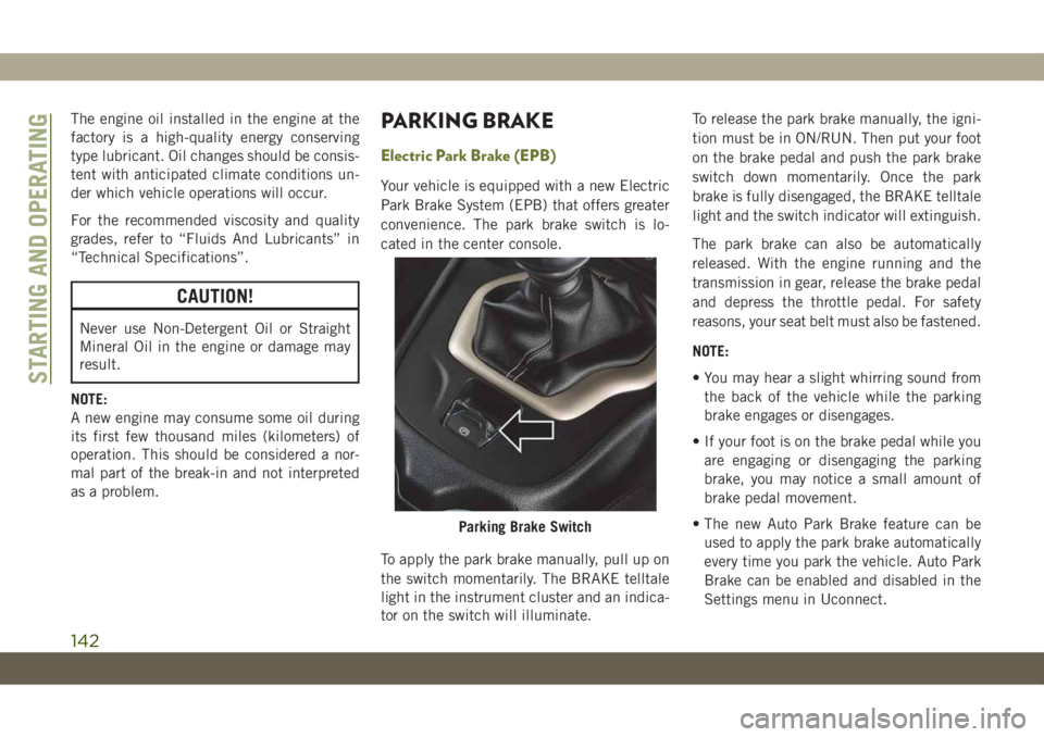
convenience. The park brake switch is lo-
cated in the center console.
To apply the park brake manually, pull up on
the switch momentarily. The BRAKE telltale
light in the instrument cluster and an indica-
tor on the switch will illuminate.To release the park brake manually, the igni-
tion must be in ON/RUN. Then put your foot
on the brake pedal and push the park brake
switch down momentarily. Once the park
brake is fully disengaged, the BRAKE telltale
light and the switch indicator will extinguish.
The park brake can also be automatically
released. With the engine running and the
transmission in gear, release the brake pedal
and depress the throttle pedal. For safety
reasons, your seat belt must also be fastened.
NOTE:
• You may hear a slight whirring sound from
the back of the vehicle while the parking
brake engages or disengages.
• If your foot is on the brake pedal while you
are engaging or disengaging the parking
brake, you may notice a small amount of
brake pedal movement.
• The new Auto Park Brake feature can be
used to apply the park brake automatically
every time you park the vehicle. Auto Park
Brake can be enabled and disabled in the
Settings menu in Uconnect.
Parking Brake Switch
STARTING AND OPERATING
142
Page 180 of 344
Adding AdBlue (UREA)
NOTE:
Driving conditions (altitude, vehicle speed,
load, etc.) will effect the amount of AdBlue
(UREA) that is used in your vehicle.
AdBlue (UREA) Fill Procedure With Pump
Nozzle
NOTE:
Refer to “Fluids And Lubricants” in the
“Technical Specifications” section for the
correct fluid type.
1. Park the vehicle on level ground. Turn off
the engine by cycling the ignition to the
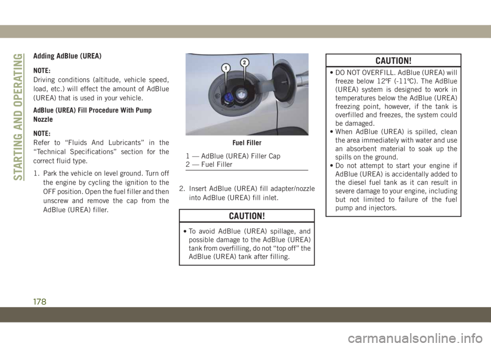
OFF position. Open the fuel filler and then
unscrew and remove the cap from the
AdBlue (UREA) filler.2. Insert AdBlue (UREA) fill adapter/nozzle
into AdBlue (UREA) fill inlet.
CAUTION!
•To avoid AdBlue (UREA) spillage, and
possible damage to the AdBlue (UREA)
tank from overfilling, do not “top off” the
AdBlue (UREA) tank after filling.
CAUTION!
• DO NOT OVERFILL. AdBlue (UREA) will
freeze below 12ºF (-11ºC). The AdBlue
(UREA) system is designed to work in
temperatures below the AdBlue (UREA)
freezing point, however, if the tank is
overfilled and freezes, the system could
be damaged.
• When AdBlue (UREA) is spilled, clean
the area immediately with water and use
an absorbent material to soak up the
spills on the ground.
• Do not attempt to start your engine if
AdBlue (UREA) is accidentally added to
the diesel fuel tank as it can result in
severe damage to your engine, including
but not limited to failure of the fuel
pump and injectors.
Fuel Filler
1 — AdBlue (UREA) Filler Cap
2 — Fuel Filler
STARTING AND OPERATING
178
Page 201 of 344
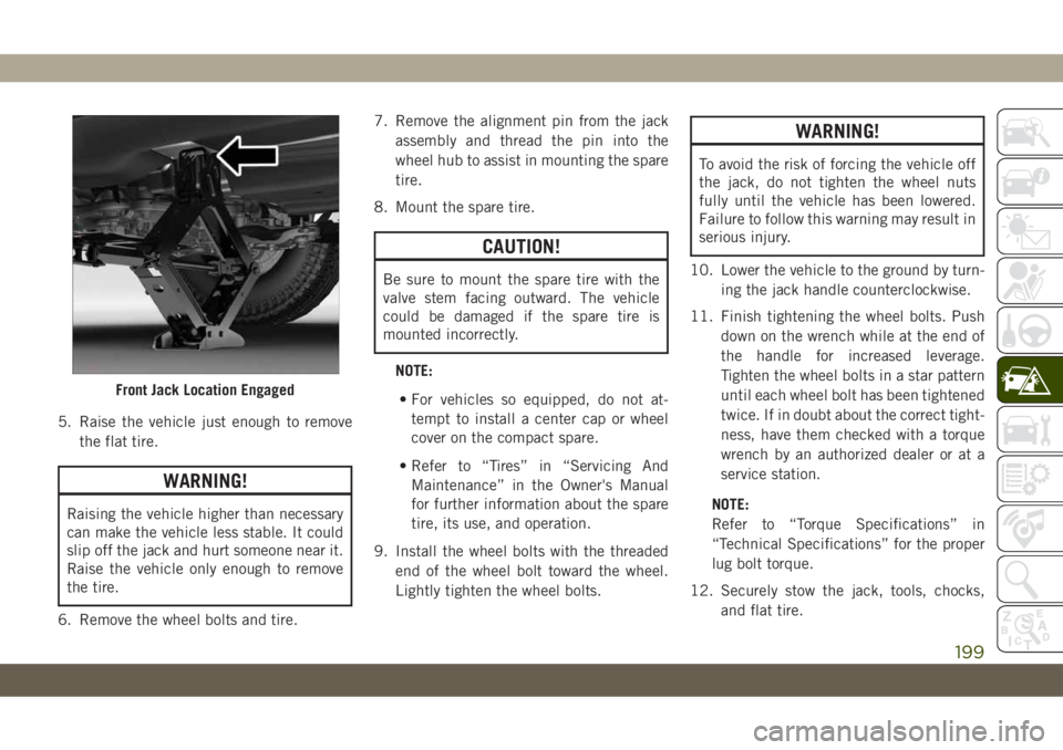
5. Raise the vehicle just enough to remove
the flat tire.
WARNING!
Raising the vehicle higher than necessary
can make the vehicle less stable. It could
slip off the jack and hurt someone near it.
Raise the vehicle only enough to remove
the tire.
6. Remove the wheel bolts and tire.7. Remove the alignment pin from the jack
assembly and thread the pin into the
wheel hub to assist in mounting the spare
tire.
8. Mount the spare tire.
CAUTION!
Be sure to mount the spare tire with the
valve stem facing outward. The vehicle
could be damaged if the spare tire is
mounted incorrectly.
NOTE:
• For vehicles so equipped, do not at-
tempt to install a center cap or wheel
cover on the compact spare.
• Refer to “Tires” in “Servicing And
Maintenance” in the Owner's Manual
for further information about the spare
tire, its use, and operation.
9. Install the wheel bolts with the threaded
end of the wheel bolt toward the wheel.
Lightly tighten the wheel bolts.
WARNING!
To avoid the risk of forcing the vehicle off
the jack, do not tighten the wheel nuts
fully until the vehicle has been lowered.
Failure to follow this warning may result in
serious injury.
10. Lower the vehicle to the ground by turn-
ing the jack handle counterclockwise.
11. Finish tightening the wheel bolts. Push
down on the wrench while at the end of
the handle for increased leverage.
Tighten the wheel bolts in a star pattern
until each wheel bolt has been tightened
twice. If in doubt about the correct tight-
ness, have them checked with a torque
wrench by an authorized dealer or at a
service station.
NOTE:
Refer to “Torque Specifications” in
“Technical Specifications” for the proper
lug bolt torque.
12. Securely stow the jack, tools, chocks,
and flat tire.
Front Jack Location Engaged
199
Page 202 of 344
WARNING!
A loose tire or jack thrown forward in a
collision or hard stop could endanger the
occupants of the vehicle. Always stow the
jack parts and the spare tire in the places
provided. Have the deflated (flat) tire re-
paired or replaced immediately.
Road Tire Installation
1. Mount the road tire on the axle.
2. Install the remaining wheel bolts with the
threaded end of the wheel bolt toward the
wheel. Lightly tighten the wheel bolts.
WARNING!
To avoid the risk of forcing the vehicle off
the jack, do not tighten the wheel nuts
fully until the vehicle has been lowered.
Failure to follow this warning may result in
serious injury.
3. Lower the vehicle to the ground by turning
the jack handle counterclockwise.4. Finish tightening the wheel bolts. Push
down on the wrench while at the end of
the handle for increased leverage. Tighten
the wheel bolts in a star pattern until each
wheel bolt has been tightened twice. If in
doubt about the correct tightness, have
them checked with a torque wrench by an
authorized dealer or service station.
Refer to “Torque Specifications” in
“Technical Specifications” for the proper
lug bolt torque.
5. Lower the jack until it is free. Remove the
wheel chocks. Reassemble the lug wrench
to the jack assembly and stow it in the
spare tire area. Secure the assembly using
the means provided. Release the parking
brake before driving the vehicle.
6. After 25 miles (40 km), check the wheel
bolt torque with a torque wrench to ensure
that all wheel bolts are properly seated
against the wheel.
Declaration Of Conformance
1. The undersigned, Tony Fabiano, repre-
senting the manufacturer, herewith de-
clares that the machinery described be-
low fulfills all relevant provisions of:
• The EC-directive 2006/42/EC on
Machinery
2. Description of machinery.
a) Generic Denomination: Vehicle Jack
b) Function: Lifting Vehicle
d) Ve-
hicle
Modelc) Model
Codef) Work-
ing Loade) Jack
Type
Jeep
®
CompassMK 1200 kg
MaxFGMF1
Jeep
CherokeeKL 1000 kg
MaxFGLF1
Jeep
WranglerJK 1000 kg
MaxFGLF2
Jeep
Grand
CherokeeWK 1700 kg
MaxFGLF3
IN CASE OF EMERGENCY
200
Page 235 of 344
WARNING!
Riding the brakes can lead to brake failure
and possibly a collision. Driving with your
foot resting or riding on the brake pedal
can result in abnormally high brake tem-
peratures, excessive lining wear, and pos-
sible brake damage. You would not have
your full braking capacity in an emergency.
Fluid Level Check — Brake Master Cylinder
The fluid level of the master cylinder should
be checked whenever the vehicle is serviced,
or immediately if the brake system warning
light is on. If necessary, add fluid to bring
level within the designated marks on the side
of the reservoir of the brake master cylinder.
Be sure to clean the top of the master cylin-
der area before removing cap. With disc
brakes, fluid level can be expected to fall as
the brake pads wear. Brake fluid level should
be checked when pads are replaced. If the
brake fluid is abnormally low, check the sys-
tem for leaks.
Refer to “Fluids And Lubricants” in “Techni-
cal Specifications” for further information.
WARNING!
• Brake fluid is poisonous and highly cor-
rosive. In the event of accidental con-
tact, immediately wash the affected
parts with water and neutral soap. Then
rinse thoroughly. Call a doctor immedi-
ately if swallowed.
• Use only manufacturer's recommended
brake fluid. Refer to “Fluids And Lubri-
cants” in “Technical Specifications” for
further information. Using the wrong
type of brake fluid can severely damage
your brake system and/or impair its per-
formance. The proper type of brake fluid
for your vehicle is also identified on the
original factory installed hydraulic mas-
ter cylinder reservoir.
• To avoid contamination from foreign
matter or moisture, use only new brake
fluid or fluid that has been in a tightly
closed container. Keep the master cylin-
der reservoir cap secured at all times.
Brake fluid in a open container absorbs
moisture from the air resulting in a lower
boiling point. This may cause it to boil
WARNING!
unexpectedly during hard or prolonged
braking, resulting in sudden brake fail-
ure. This could result in a collision.
• Overfilling the brake fluid reservoir can
result in spilling brake fluid on hot en-
gine parts, causing the brake fluid to
catch fire. Brake fluid can also damage
painted and vinyl surfaces, care should
be taken to avoid its contact with these
surfaces.
• Do not allow petroleum based fluid to
contaminate the brake fluid. Brake seal
components could be damaged, causing
partial or complete brake failure. This
could result in a collision.
Manual Transmission — If Equipped
Fluid Level Check
Check the fluid level by removing the fill
plug. The fluid level should be between the
bottom of the fill hole and a point not more
than 3/16 inch (4.7 mm) below the bottom of
the hole.
233
Page 256 of 344
nuts/bolts should be torqued using a properly
calibrated torque wrench using a high quality
six sided (hex) deep wall socket.
Torque Specifications
Lug Nut/Bolt
Torque**Lug Nut/Bolt
SizeLug Nut/Bolt
Socket Size
100 Ft-Lbs
(135 N·m)M12 x 1.25 19 mm
**Use only an authorized dealer recom-
mended lug nuts/bolts and clean or remove
any dirt or oil before tightening.
Inspect the wheel mounting surface prior to
mounting the tire and remove any corrosion
or loose particles.
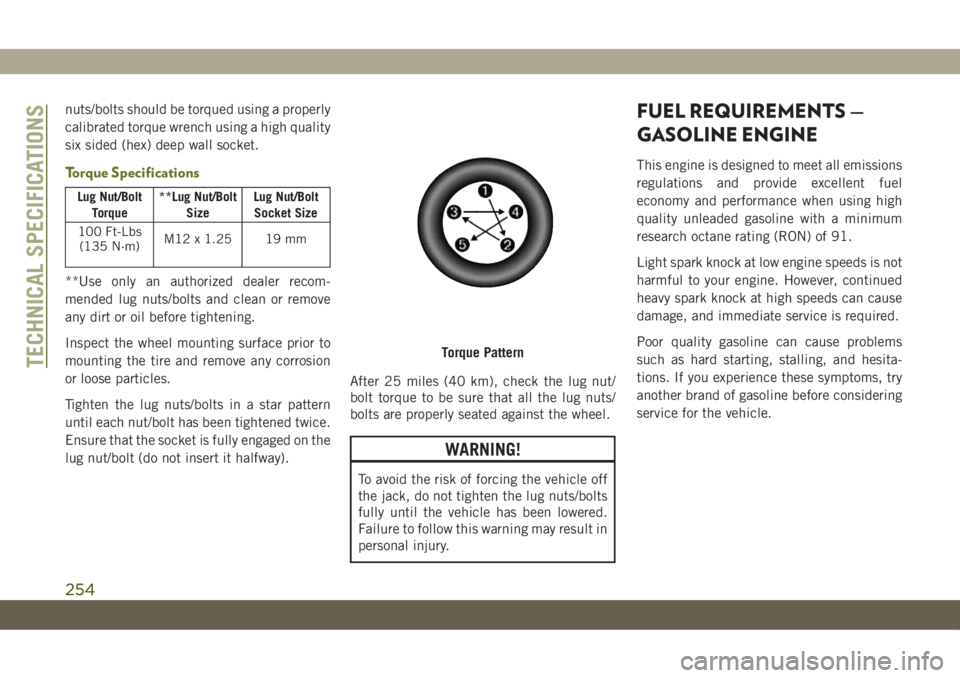
Tighten the lug nuts/bolts in a star pattern
until each nut/bolt has been tightened twice.
Ensure that the socket is fully engaged on the
lug nut/bolt (do not insert it halfway).After 25 miles (40 km), check the lug nut/
bolt torque to be sure that all the lug nuts/
bolts are properly seated against the wheel.
WARNING!
To avoid the risk of forcing the vehicle off
the jack, do not tighten the lug nuts/bolts
fully until the vehicle has been lowered.
Failure to follow this warning may result in
personal injury.
FUEL REQUIREMENTS —
GASOLINE ENGINE
This engine is designed to meet all emissions
regulations and provide excellent fuel
economy and performance when using high
quality unleaded gasoline with a minimum
research octane rating (RON) of 91.
Light spark knock at low engine speeds is not
harmful to your engine. However, continued
heavy spark knock at high speeds can cause
damage, and immediate service is required.
Poor quality gasoline can cause problems
such as hard starting, stalling, and hesita-
tions. If you experience these symptoms, try
another brand of gasoline before considering
service for the vehicle.
Torque PatternTECHNICAL SPECIFICATIONS
254
Page 258 of 344
MMT In Gasoline
Methylcyclopentadienyl Manganese Tricar-
bonyl (MMT) is a manganese containing me-
tallic additive that is blended into some gaso-
line to increase octane. Gasoline blended
with MMT provides no performance advan-
tage beyond gasoline of the same octane
number without MMT. Gasoline blended with
MMT reduces spark plug life and reduces
emission system performance in some ve-
hicles. The manufacturer recommends that
gasoline without MMT be used in your ve-
hicle. The MMT content of gasoline may not
be indicated on the gasoline pump; there-
fore, you should ask your gasoline retailer
whether or not his/her gasoline contains
MMT.
Materials Added To Fuel
Indiscriminate use of fuel system cleaning
agents should be avoided. Many of these
materials intended for gum and varnish re-
moval may contain active solvents or similar
ingredients. These can harm fuel system gas-
ket and diaphragm materials.
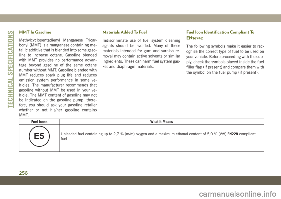
Fuel Icon Identification Compliant To
EN16942
The following symbols make it easier to rec-
ognize the correct type of fuel to be used on
your vehicle. Before proceeding with the sup-
ply, check the symbols placed inside the fuel
filler flap (if present) and compare them with
the symbol on the fuel pump (if present).
Fuel IconsWhat It Means
E5Unleaded fuel containing up to 2,7 % (m/m) oxygen and a maximum ethanol content of 5,0 % (V/V)EN228compliant
fuel
TECHNICAL SPECIFICATIONS
256
Page 260 of 344
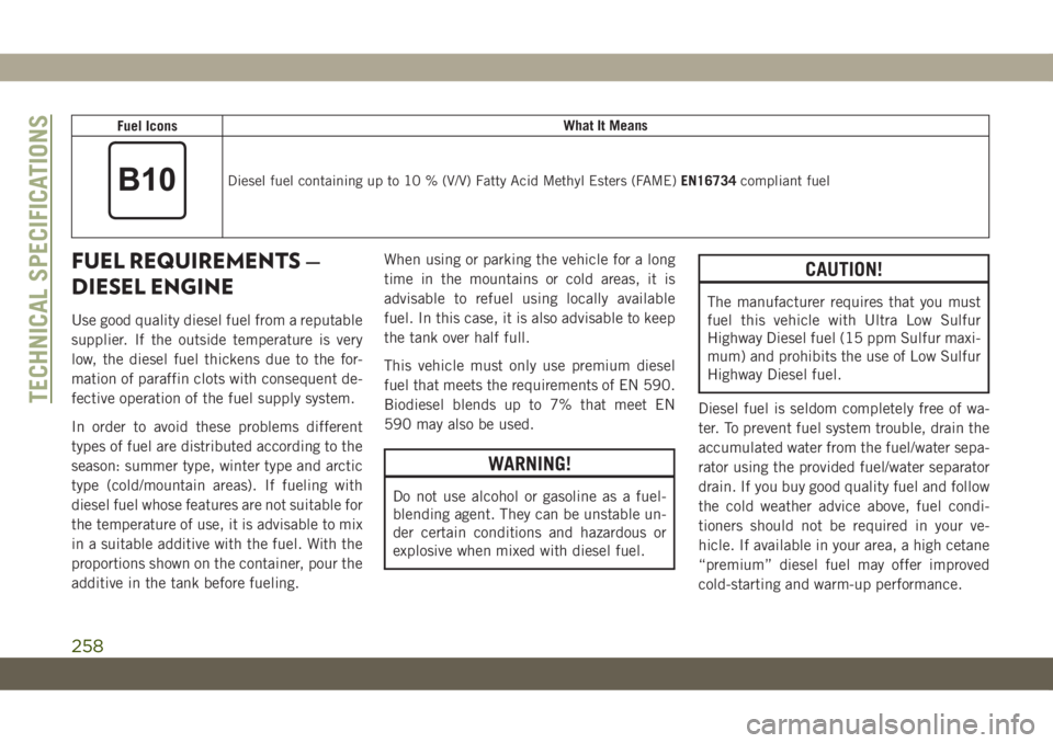
Fuel IconsWhat It Means
Diesel fuel containing up to 10 % (V/V) Fatty Acid Methyl Esters (FAME)EN16734compliant fuel
FUEL REQUIREMENTS —
DIESEL ENGINE
Use good quality diesel fuel from a reputable
supplier. If the outside temperature is very
low, the diesel fuel thickens due to the for-
mation of paraffin clots with consequent de-
fective operation of the fuel supply system.
In order to avoid these problems different
types of fuel are distributed according to the
season: summer type, winter type and arctic
type (cold/mountain areas). If fueling with
diesel fuel whose features are not suitable for
the temperature of use, it is advisable to mix
in a suitable additive with the fuel. With the
proportions shown on the container, pour the
additive in the tank before fueling.When using or parking the vehicle for a long
time in the mountains or cold areas, it is
advisable to refuel using locally available
fuel. In this case, it is also advisable to keep
the tank over half full.
This vehicle must only use premium diesel
fuel that meets the requirements of EN 590.
Biodiesel blends up to 7% that meet EN
590 may also be used.
WARNING!
Do not use alcohol or gasoline as a fuel-
blending agent. They can be unstable un-
der certain conditions and hazardous or
explosive when mixed with diesel fuel.
CAUTION!
The manufacturer requires that you must
fuel this vehicle with Ultra Low Sulfur
Highway Diesel fuel (15 ppm Sulfur maxi-
mum) and prohibits the use of Low Sulfur
Highway Diesel fuel.
Diesel fuel is seldom completely free of wa-
ter. To prevent fuel system trouble, drain the
accumulated water from the fuel/water sepa-
rator using the provided fuel/water separator
drain. If you buy good quality fuel and follow
the cold weather advice above, fuel condi-
tioners should not be required in your ve-
hicle. If available in your area, a high cetane
“premium” diesel fuel may offer improved
cold-starting and warm-up performance.
TECHNICAL SPECIFICATIONS
258