change wheel JEEP CHEROKEE 2020 Owner handbook (in English)
[x] Cancel search | Manufacturer: JEEP, Model Year: 2020, Model line: CHEROKEE, Model: JEEP CHEROKEE 2020Pages: 332, PDF Size: 8.87 MB
Page 172 of 332
STARTING AND OPERATING
170
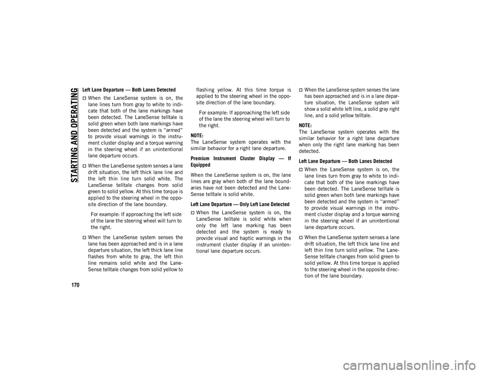
Left Lane Departure — Both Lanes Detected
When the LaneSense system is on, the
lane lines turn from gray to white to indi-
cate that both of the lane markings have
been detected. The LaneSense telltale is
solid green when both lane markings have
been detected and the system is “armed”
to provide visual warnings in the instru -
ment cluster display and a torque warning
in the steering wheel if an unintentional
lane departure occurs.
When the LaneSense system senses a lane
drift situation, the left thick lane line and
the left thin line turn solid white. The
LaneSense telltale changes from solid
green to solid yellow. At this time torque is
applied to the steering wheel in the oppo-
site direction of the lane boundary.
For example: If approaching the left side
of the lane the steering wheel will turn to
the right.
When the LaneSense system senses the
lane has been approached and is in a lane
departure situation, the left thick lane line
flashes from white to gray, the left thin
line remains solid white and the Lane-
Sense telltale changes from solid yellow to flashing yellow. At this time torque is
applied to the steering wheel in the oppo-
site direction of the lane boundary.
For example: If approaching the left side
of the lane the steering wheel will turn to
the right.
NOTE:
The LaneSense system operates with the
similar behavior for a right lane departure.
Premium Instrument Cluster Display — If
Equipped
When the LaneSense system is on, the lane
lines are gray when both of the lane bound -
aries have not been detected and the Lane -
Sense telltale is solid white.
Left Lane Departure — Only Left Lane Detected
When the LaneSense system is on, the
LaneSense telltale is solid white when
only the left lane marking has been
detected and the system is ready to
provide visual and haptic warnings in the
instrument cluster display if an uninten-
tional lane departure occurs.
When the LaneSense system senses the lane
has been approached and is in a lane depar -
ture situation, the LaneSense system will
show a solid white left line, a solid gray right
line, and a solid yellow telltale.
NOTE:
The LaneSense system operates with the
similar behavior for a right lane departure
when only the right lane marking has been
detected.
Left Lane Departure — Both Lanes Detected
When the LaneSense system is on, the
lane lines turn from gray to white to indi-
cate that both of the lane markings have
been detected. The LaneSense telltale is
solid green when both lane markings have
been detected and the system is “armed”
to provide visual warnings in the instru -
ment cluster display and a torque warning
in the steering wheel if an unintentional
lane departure occurs.
When the LaneSense system senses a lane
drift situation, the left thick lane line and
left thin line turn solid yellow. The Lane-
Sense telltale changes from solid green to
solid yellow. At this time torque is applied
to the steering wheel in the opposite direc-
tion of the lane boundary.
2020_JEEP_CHEROKEE_UG_RHD_UK.book Page 170
Page 173 of 332
171
(Continued)
For example: If approaching the left side
of the lane the steering wheel will turn to
the right.
When the LaneSense system senses the
lane has been approached and is in a lane
departure situation, the left thick lane line
flashes yellow (on/off) and the left thin
line remains solid yellow. The LaneSense
telltale changes from solid yellow to
flashing yellow. At this time torque is
applied to the steering wheel in the oppo-
site direction of the lane boundary.For example: If approaching the left side
of the lane the steering wheel will turn to
the right.
NOTE:
The LaneSense system operates with the
similar behavior for a right lane departure.
Changing LaneSense Status
The LaneSense system has settings to adjust
the intensity of the torque warning and the
warning zone sensitivity (early/late) that you
can configure through the Uconnect system
screen.
Refer to “Uconnect Settings” in “Multi -
media” in the Owner’s Manual for further
information. NOTE:
When enabled, the system operates above
37 mph (60 km/h) and below 112 mph
(180 km/h).
Use of the turn signal suppresses the
warnings.
The system will not apply torque to the
steering wheel whenever a safety system
engages (Anti-Lock Brakes, Traction
Control System, Electronic Stability
Control, Forward Collision Warning, etc.).
PARKVIEW REAR BACK UP
CAMERA — IF EQUIPPED
Your vehicle may be equipped with the
ParkView Rear Back Up Camera that allows
you to see an on-screen image of the rear
surroundings of your vehicle whenever the
gear selector is put into REVERSE. The
image will be displayed in the touchscreen
display along with a caution note to “check
entire surroundings” across the top of the
screen. After five seconds this note will
disappear. The ParkView camera is located
on the rear of the vehicle above the rear
license plate. NOTE:
The ParkView Rear Back Up Camera has
programmable modes of operation that may
be selected through the Uconnect System.
Refer to “Uconnect Settings” in “Multi
-
media” in the Owner’s Manual for further
information.
WARNING!
Drivers must be careful when backing up
even when using the ParkView Rear Back
Up Camera. Always check carefully behind
your vehicle, and be sure to check for
pedestrians, animals, other vehicles,
obstructions, or blind spots before backing
up. You are responsible for the safety of
your surroundings and must continue to
pay attention while backing up. Failure to
do so can result in serious injury or death.
CAUTION!
To avoid vehicle damage, ParkView
should only be used as a parking aid. The
ParkView camera is unable to view every
obstacle or object in your drive path.
2020_JEEP_CHEROKEE_UG_RHD_UK.book Page 171
Page 180 of 332
STARTING AND OPERATING
178
Gross Vehicle Weight Rating (GVWR)
The Gross Vehicle Weight Rating (GVWR) is
the total permissible weight of your vehicle
including driver, passengers, vehicle,
options and cargo. The label also specifies
maximum capacities of front and rear axle
systems (GAWR). Total load must be limited
so GVWR and front and rear GAWR are not
exceeded.
Payload
The payload of a vehicle is defined as the
allowable load weight a truck can carry,
including the weight of the driver, all passen-
gers, options and cargo.
Gross Axle Weight Rating (GAWR)
The Gross Axle Weight Rating (GAWR) is the
maximum permissible load on the front and
rear axles. The load must be distributed in
the cargo area so that the GAWR of each axle
is not exceeded.
Each axle GAWR is determined by the
components in the system with the lowest
load carrying capacity (axle, springs, tires or
wheels). Heavier axles or suspension compo -nents sometimes specified by purchasers for
increased durability does not necessarily
increase the vehicle's GVWR.
Curb Weight
The curb weight of a vehicle is defined as the
total weight of the vehicle with all fluids,
including vehicle fuel, at full capacity condi
-
tions, and with no occupants or cargo loaded
into the vehicle. The front and rear curb
weight values are determined by weighing
your vehicle on a commercial scale before
any occupants or cargo are added.
Loading
The actual total weight and the weight of the
front and rear of your vehicle at the ground
can best be determined by weighing it when
it is loaded and ready for operation.
The entire vehicle should first be weighed on
a commercial scale to ensure that the GVWR
has not been exceeded. The weight on the
front and rear of the vehicle should then be
determined separately to be sure that the
load is properly distributed over the front and
rear axle. Weighing the vehicle may show
that the GAWR of either the front or rear
axles has been exceeded but the total load is
within the specified GVWR. If so, weight must be shifted from front to rear or rear to
front as appropriate until the specified
weight limitations are met. Store the heavier
items down low and be sure that the weight
is distributed equally. Stow all loose items
securely before driving.
Improper weight distributions can have an
adverse effect on the way your vehicle steers
and handles and the way the brakes operate.
CAUTION!
Do not load your vehicle any heavier than
the GVWR or the maximum front and rear
GAWR. If you do, parts on your vehicle can
break, or it can change the way your
vehicle handles. This could cause you to
lose control. Also overloading can shorten
the life of your vehicle.
2020_JEEP_CHEROKEE_UG_RHD_UK.book Page 178
Page 196 of 332
IN CASE OF EMERGENCY
194
JACKING AND TIRE
CHANGING Jack Location/Spare Tire Stowage
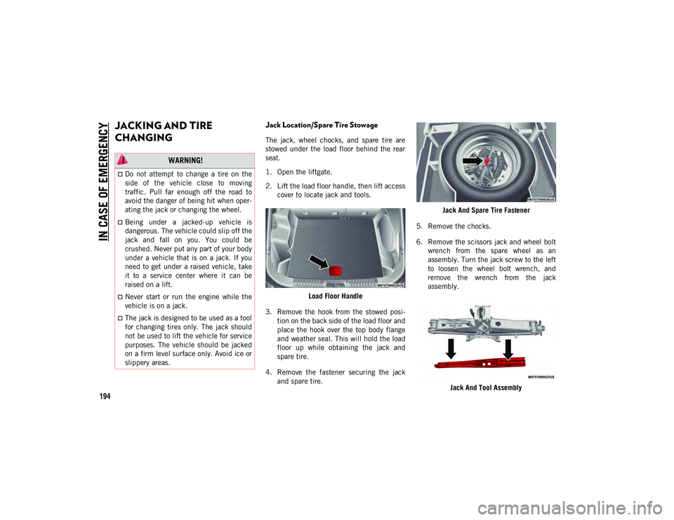
The jack, wheel chocks, and spare tire are
stowed under the load floor behind the rear
seat.
1. Open the liftgate.
2. Lift the load floor handle, then lift accesscover to locate jack and tools.
Load Floor Handle
3. Remove the hook from the stowed posi -
tion on the back side of the load floor and
place the hook over the top body flange
and weather seal. This will hold the load
floor up while obtaining the jack and
spare tire.
4. Remove the fastener securing the jack and spare tire. Jack And Spare Tire Fastener
5. Remove the chocks.
6. Remove the scissors jack and wheel bolt wrench from the spare wheel as an
assembly. Turn the jack screw to the left
to loosen the wheel bolt wrench, and
remove the wrench from the jack
assembly.
Jack And Tool Assembly
WARNING!
Do not attempt to change a tire on the
side of the vehicle close to moving
traffic. Pull far enough off the road to
avoid the danger of being hit when oper -
ating the jack or changing the wheel.
Being under a jacked-up vehicle is
dangerous. The vehicle could slip off the
jack and fall on you. You could be
crushed. Never put any part of your body
under a vehicle that is on a jack. If you
need to get under a raised vehicle, take
it to a service center where it can be
raised on a lift.
Never start or run the engine while the
vehicle is on a jack.
The jack is designed to be used as a tool
for changing tires only. The jack should
not be used to lift the vehicle for service
purposes. The vehicle should be jacked
on a firm level surface only. Avoid ice or
slippery areas.
2020_JEEP_CHEROKEE_UG_RHD_UK.book Page 194
Page 197 of 332
195(Continued)
NOTE:
The jack handle attaches to the side of the
jack with two attachment points. When the
jack is partially expanded, the tension
between the two attachment points holds the
jack handle in place.
7. Remove the spare tire.
Preparations For Jacking
1. Park the vehicle on a firm level surface asfar from the edge of the roadway as
possible. Avoid icy or slippery areas. 2. Turn on the Hazard Warning flasher.
3. Apply the parking brake.
4. Place the gear selector into PARK (P)
(automatic transmission) or REVERSE
(R) (manual transmission).
5. Turn the ignition OFF.
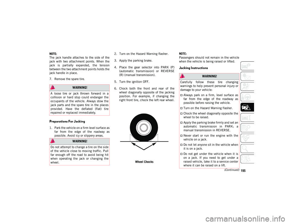
6. Chock both the front and rear of the wheel diagonally opposite of the jacking
position. For example, if changing the
right front tire, chock the left rear wheel.
Wheel Chocks NOTE:
Passengers should not remain in the vehicle
when the vehicle is being raised or lifted.
Jacking Instructions
WARNING!
A loose tire or jack thrown forward in a
collision or hard stop could endanger the
occupants of the vehicle. Always stow the
jack parts and the spare tire in the places
provided. Have the deflated (flat) tire
repaired or replaced immediately.
WARNING!
Do not attempt to change a tire on the side
of the vehicle close to moving traffic. Pull
far enough off the road to avoid being hit
when operating the jack or changing the
wheel.
WARNING!
Carefully follow these tire changing
warnings to help prevent personal injury or
damage to your vehicle:
Always park on a firm, level surface as
far from the edge of the roadway as
possible before raising the vehicle.
Turn on the Hazard Warning flasher.
Chock the wheel diagonally opposite the
wheel to be raised.
Apply the parking brake firmly and set an
automatic transmission in PARK; a
manual transmission in REVERSE.
Never start or run the engine with the
vehicle on a jack.
Do not let anyone sit in the vehicle when
it is on a jack.
Do not get under the vehicle when it is
on a jack. If you need to get under a
raised vehicle, take it to a service center
where it can be raised on a lift.
2020_JEEP_CHEROKEE_UG_RHD_UK.book Page 195
Page 198 of 332
IN CASE OF EMERGENCY
196
1. Remove the spare tire, jack, wheelchocks, and wheel bolt wrench.
2. If equipped with aluminum wheels where the center cap covers the wheel bolts,
use the wheel bolt wrench to pry the
center cap off carefully before raising the
vehicle. 3. Before raising the vehicle, use the wheel
bolt wrench to loosen, but not remove,
the wheel bolts on the wheel with the flat
tire. Turn the wheel bolts counterclock -
wise one turn while the wheel is still on
the ground.
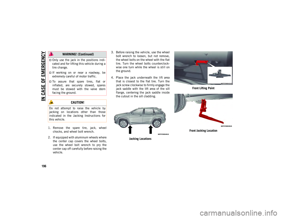
4. Place the jack underneath the lift area that is closest to the flat tire. Turn the
jack screw clockwise to firmly engage the
jack saddle with the lift area of the sill
flange, centering the jack saddle inside
the cutout in the sill cladding.
Jacking Locations Front Lifting Point
Front Jacking Location
Only use the jack in the positions indi -
cated and for lifting this vehicle during a
tire change.
If working on or near a roadway, be
extremely careful of motor traffic.
To assure that spare tires, flat or
inflated, are securely stowed, spares
must be stowed with the valve stem
facing the ground.
CAUTION!
Do not attempt to raise the vehicle by
jacking on locations other than those
indicated in the Jacking Instructions for
this vehicle.
WARNING! (Continued)
2020_JEEP_CHEROKEE_UG_RHD_UK.book Page 196
Page 204 of 332
IN CASE OF EMERGENCY
202
Jack Usage Precautions
To complete the Use and Maintenance
Handbook to which this supplement is
attached, given below are some instructions
on the proper use of the jack.MaintenanceMake sure grime does not build up on the
“worm screw.”
Keep the “worm screw” lubricated.
Never modify the jack.
Conditions Of Non-Use:
Temperatures below −40°F (-40°C).
On sandy or muddy ground.
On uneven ground.
On steep roads.
In extreme weather conditions: thunder -
storms, typhoons, hurricanes, blizzards,
storms, etc.
NOTE:
The jack requires no adjustment.
The jack cannot be repaired, and in the
event of a fault, it must be replaced by
another genuine one.
No tool other than its cranking device may
be fitted on the jack.
WARNING!
When using the crank, make sure it turns
freely without the risk of scraping hands
against the ground.
Even the moving parts of the jack, the
“worm screw” and joints can cause
injuries: avoid contact with them. Clean it
thoroughly if dirtied with grease.
CAUTION!
The jack is a tool designed exclusively for
changing a wheel, in case of a puncture or
damage to a tire of the vehicle on which it
is fitted or on vehicles of the same model.
Any other use, e.g. to jack up other vehicle
models or different things, is strictly
prohibited. Never use it to carry out
maintenance or repairs under the vehicle
or to change summer/winter wheels and
vice versa. Never go under the raised
vehicle. If any work under the vehicle is
necessary, contact an authorized dealer.
Incorrect placing of the jack can cause the
vehicle to drop: use it only in the positions
indicated. Do not use the jack for loads
higher than that specified on the label.
Never start the engine with vehicle raised.
If the vehicle is raised more than
necessary, everything can become more
unstable, with the risk of the vehicle
dropping violently. Therefore raise the
vehicle only as much as necessary for the
wheel/spare.
2020_JEEP_CHEROKEE_UG_RHD_UK.book Page 202
Page 207 of 332
205
(Continued)
(Continued)
rafts, or similar inflatable items. However,
use only the Air Pump Hose and make sure
the Mode Select Knob is in the Air Mode
when inflating such items to avoid
injecting sealant into them. The Tire
Service Kit Sealant is only intended to seal
punctures less than 1/4 inch (6 mm)
diameter in the tread of your tire.
Do not lift or carry the Tire Service Kit by
the hoses.
Sealing A Tire With Tire Service Kit
(A) Whenever You Stop To Use Tire Service
Kit:
1. Pull over to a safe location and turn on the vehicle’s Hazard Warning flashers.
2. Verify that the valve stem (on the wheel with the deflated tire) is in a position that
is near to the ground. This will allow the
Tire Service Kit Hoses and to reach the
valve stem and keep the Tire Service Kit
flat on the ground. This will provide the
best positioning of the kit when injecting
the sealant into the deflated tire and
running the air pump. Move the vehicle
as necessary to place the valve stem in
this position before proceeding.
WARNING!
Do not attempt to seal a tire on the side
of the vehicle closest to traffic. Pull far
enough off the road to avoid the danger
of being hit when using the Tire Service
Kit.
Do not use Tire Service Kit or drive the
vehicle under the following circum -
stances:
If the puncture in the tire tread is
approximately 1/4 inch (6 mm) or
larger.
If the tire has any sidewall damage.
If the tire has any damage from driving with extremely low tire pres-
sure.
If the tire has any damage fromdriving on a flat tire.
If the wheel has any damage.
If you are unsure of the condition ofthe tire or the wheel.
Keep Tire Service Kit away from open
flames or heat source.
A loose Tire Service Kit thrown forward in
a collision or hard stop could endanger
the occupants of the vehicle. Always
stow the Tire Service Kit in the place
provided. Failure to follow these warn -
ings can result in injuries that are serious
or fatal to you, your passengers, and
others around you.
Take care not to allow the contents of
Tire Service Kit to come in contact with
hair, eyes, or clothing. Tire Service Kit
sealant is harmful if inhaled, swallowed,
or absorbed through the skin. It causes
skin, eye, and respiratory irritation.
Flush immediately with plenty of water if
there is any contact with eyes or skin.
Change clothing as soon as possible, if
there is any contact with clothing.
WARNING! (Continued)
Tire Service Kit Sealant solution
contains latex. In case of an allergic
reaction or rash, consult a physician
immediately. Keep Tire Service Kit out
of reach of children. If swallowed, rinse
mouth immediately with plenty of water
and drink plenty of water. Do not induce
vomiting! Consult a physician immedi -
ately.
WARNING! (Continued)
2020_JEEP_CHEROKEE_UG_RHD_UK.book Page 205
Page 247 of 332
245
(Continued)
NOTE:
Wheel Valve Stem must be replaced as well
when installing new tires due to wear and
tear in existing tires.
Keep dismounted tires in a cool, dry place
with as little exposure to light as possible.
Protect tires from contact with oil, grease,
and gasoline.
Replacement Tires
The tires on your new vehicle provide a
balance of many characteristics. They should
be inspected regularly for wear and correct
cold tire inflation pressures. The manufac-
turer strongly recommends that you use tires
equivalent to the originals in size, quality
and performance when replacement is
needed. Refer to the paragraph on “Tread
Wear Indicators” in this section. Refer to the
Tire and Loading Information placard or the
Vehicle Certification Label for the size desig -
nation of your tire. The Load Index and
Speed Symbol for your tire will be found on
the original equipment tire sidewall.
It is recommended to replace the two front
tires or two rear tires as a pair. Replacing just
one tire can seriously affect your vehicle’s handling. If you ever replace a wheel, make
sure that the wheel’s specifications match
those of the original wheels.
It is recommended you contact an authorized
tire dealer or original equipment dealer with
any questions you may have on tire specifica
-
tions or capability. Failure to use equivalent
replacement tires may adversely affect the
safety, handling, and ride of your vehicle. WARNING!
Do not use a tire, wheel size, load rating,
or speed rating other than that specified
for your vehicle. Some combinations of
unapproved tires and wheels may change
suspension dimensions and performance
characteristics, resulting in changes to
steering, handling, and braking of your
vehicle. This can cause unpredictable
handling and stress to steering and
suspension components. You could lose
control and have a collision resulting in
serious injury or death. Use only the tire
and wheel sizes with load ratings
approved for your vehicle.
Never use a tire with a smaller load index
or capacity, other than what was origi -
nally equipped on your vehicle. Using a
tire with a smaller load index could result
in tire overloading and failure. You could
lose control and have a collision.
Failure to equip your vehicle with tires
having adequate speed capability can
result in sudden tire failure and loss of
vehicle control.
CAUTION!
Replacing original tires with tires of a
different size may result in false
speedometer and odometer readings.
WARNING! (Continued)
2020_JEEP_CHEROKEE_UG_RHD_UK.book Page 245
Page 283 of 332
281
NOTE:
To use Android Auto™, make sure you are in
an area with cellular coverage. Android
Auto™ may use cellular data and your
cellular coverage is shown in the upper right
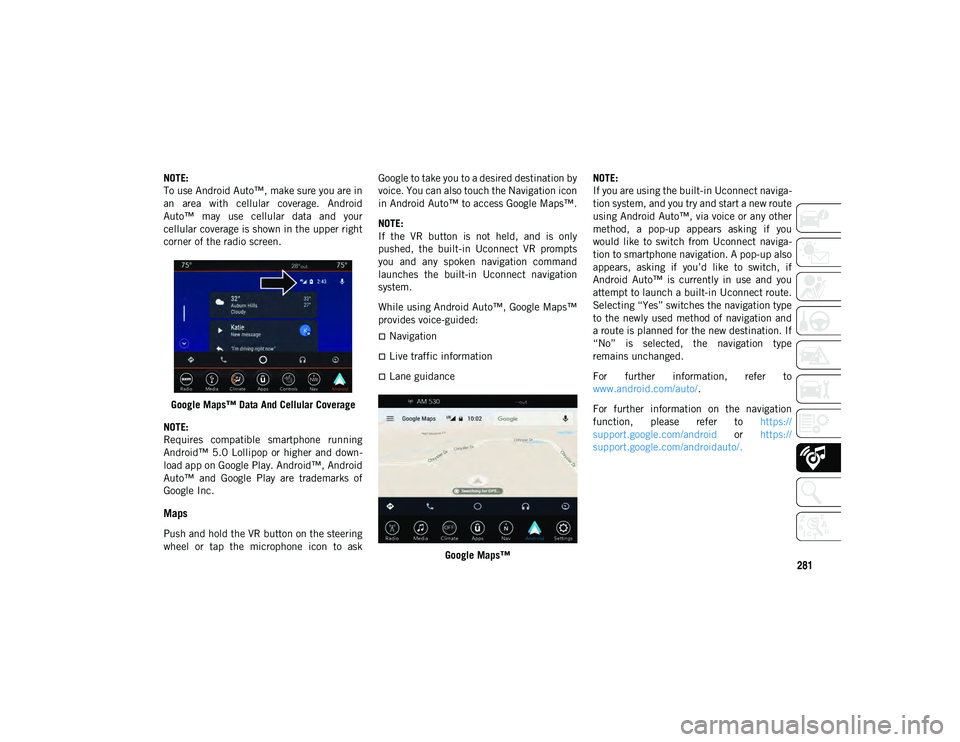
corner of the radio screen.Google Maps™ Data And Cellular Coverage
NOTE:
Requires compatible smartphone running
Android™ 5.0 Lollipop or higher and down -
load app on Google Play. Android™, Android
Auto™ and Google Play are trademarks of
Google Inc.
Maps
Push and hold the VR button on the steering
wheel or tap the microphone icon to ask Google to take you to a desired destination by
voice. You can also touch the Navigation icon
in Android Auto™ to access Google Maps™.
NOTE:
If the VR button is not held, and is only
pushed, the built-in Uconnect VR prompts
you and any spoken navigation command
launches the built-in Uconnect navigation
system.
While using Android Auto™, Google Maps™
provides voice-guided:
Navigation
Live traffic information
Lane guidance
Google Maps™ NOTE:
If you are using the built-in Uconnect naviga
-
tion system, and you try and start a new route
using Android Auto™, via voice or any other
method, a pop-up appears asking if you
would like to switch from Uconnect naviga -
tion to smartphone navigation. A pop-up also
appears, asking if you’d like to switch, if
Android Auto™ is currently in use and you
attempt to launch a built-in Uconnect route.
Selecting “Yes” switches the navigation type
to the newly used method of navigation and
a route is planned for the new destination. If
“No” is selected, the navigation type
remains unchanged.
For further information, refer to
www.android.com/auto/ .
For further information on the navigation
function, please refer to https://
support.google.com/android or https://
support.google.com/androidauto/.
2020_JEEP_CHEROKEE_UG_RHD_UK.book Page 281