torque JEEP CHEROKEE 2021 Owner handbook (in English)
[x] Cancel search | Manufacturer: JEEP, Model Year: 2021, Model line: CHEROKEE, Model: JEEP CHEROKEE 2021Pages: 332, PDF Size: 8.87 MB
Page 153 of 332
151
When operating your vehicle in 4WD LOW,
the engine speed is approximately three
times that of the normal driving mode at a
given road speed. Take care not to overspeed
the engine and do not exceed 50 mph
(80 km/h).
Proper operation of four-wheel drive vehicles
depends on tires of equal size, type, and
circumference on each wheel. Any difference
will adversely affect shifting and cause
damage to the driveline components.
Because four-wheel drive provides improved
traction, there is a tendency to exceed safe
turning and stopping speeds. Do not go
faster than road conditions permit.
Shift Positions
For additional information on the appropriate
use of each 4WD system mode position, see
the information below:
NEUTRAL (N)
This range disengages the driveline from the
powertrain.
4WD LOW
This range is for low speed four-wheel drive.
It provides an additional gear reduction
which allows for increased torque to be deliv-
ered to both the front and rear wheels while
providing maximum pulling power for loose,
slippery road surfaces only. Do not exceed
25 mph (40 km/h).
NOTE:
Refer to “Selec-Terrain — If Equipped” for
further information on the various positions
and their intended usages.
Shifting Procedures
Shifting Into 4X4 LOW
With the vehicle at speeds of 0 to 3 mph (0
to 5 km/h), the ignition in the ON mode and
the engine running, shift the transmission
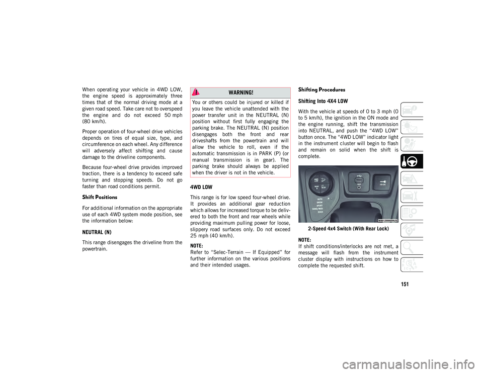
into NEUTRAL, and push the “4WD LOW”
button once. The “4WD LOW” indicator light
in the instrument cluster will begin to flash
and remain on solid when the shift is
complete.
2-Speed 4x4 Switch (With Rear Lock)
NOTE:
If shift conditions/interlocks are not met, a
message will flash from the instrument
cluster display with instructions on how to
complete the requested shift.
WARNING!
You or others could be injured or killed if
you leave the vehicle unattended with the
power transfer unit in the NEUTRAL (N)
position without first fully engaging the
parking brake. The NEUTRAL (N) position
disengages both the front and rear
driveshafts from the powertrain and will
allow the vehicle to roll, even if the
automatic transmission is in PARK (P) (or
manual transmission is in gear). The
parking brake should always be applied
when the driver is not in the vehicle.
2020_JEEP_CHEROKEE_UG_RHD_UK.book Page 151
Page 170 of 332
STARTING AND OPERATING
168
PARKSENSE ACTIVE PARK
ASSIST SYSTEM — IF
EQUIPPED
The ParkSense Active Park Assist system is
intended to assist the driver during parallel
and perpendicular parking maneuvers by
identifying a proper parking space, providing
audible/visual instructions, and controlling
the steering wheel. The ParkSense Active
Park Assist system is defined as “semi-auto-
matic” since the driver maintains control of
the accelerator, gear selector and brakes.
Depending on the driver's parking maneuver
selection, the ParkSense Active Park Assist
system is capable of maneuvering a vehicle
into a parallel or a perpendicular parking
space on either side (i.e., driver side or
passenger side).
NOTE:
The driver is always responsible for
controlling the vehicle, responsible for any
surrounding objects, and must intervene
as required.
The system is provided to assist the driver
and not to substitute the driver.
During a semi-automatic maneuver, if the
driver touches the steering wheel after
being instructed to remove their hands
from the steering wheel, the system will
cancel, and the driver will be required to
manually complete the parking maneuver.
The system may not work in all conditions
(e.g. environmental conditions such as
heavy rain, snow, etc., or if searching for a
parking space that has surfaces that will
absorb the ultrasonic sensor waves).
New vehicles from the dealer must have at
least 30 miles (48 km) accumulated
before the ParkSense Active Park Assist
system is fully calibrated and performs
accurately. This is due to the system’s
dynamic vehicle calibration to improve the
performance of the feature. The system
will also continuously perform the
dynamic vehicle calibration to account for
differences such as over or under inflated
tires and new tires.
The ParkSense Active Park Assist system can
be enabled and disabled with the ParkSense
Active Park Assist switch, located on the
switch panel below the Uconnect display. To enable the ParkSense Active
Park Assist system, push the Park
-
Sense Active Park Assist switch
once (LED turns on).
To disable the ParkSense Active Park Assist
system, push the ParkSense Active Park
Assist switch again (LED turns off).
Refer to the Owner’s Manual for further infor -
mation.LANESENSE — IF EQUIPPED
LaneSense Operation
The LaneSense system is operational at
speeds above 37 mph (60 km/h) and below
112 mph (180 km/h). The LaneSense
system uses a forward looking camera to
detect lane markings and measure vehicle
position within the lane boundaries.
When both lane markings are detected and the
driver unintentionally drifts out of the lane (no
turn signal applied), the LaneSense system
provides a haptic warning in the form of torque
applied to the steering wheel, as well as a
visual warning in the instrument cluster
display, to prompt the driver to remain within
the lane boundaries. The LaneSense system
2020_JEEP_CHEROKEE_UG_RHD_UK.book Page 168
Page 171 of 332
169
will also operate in this manner when only a
single lane marking is detected and the driver
unintentionally drifts across the lane marking
(no turn signal applied).
The driver may manually override the haptic
warning by applying torque into the steering
wheel at any time.
When only a single lane marking is detected
and the driver unintentionally drifts across
the lane marking (no turn signal applied), the
LaneSense system provides a haptic warning
in the form of torque applied to the steering
wheel, as well as a visual warning in the
instrument cluster display, to prompt the
driver to remain within the lane boundaries.
NOTE:
When operating conditions have been met,
the LaneSense system will monitor if the
driver’s hands are on the steering wheel and
provide an audible and visual warning to the
driver when the driver’s hands are not
detected on the steering wheel. The system
will cancel if the driver does not return their
hands to the wheel.Turning LaneSense On Or Off
The default status of LaneSense is “off”.
The LaneSense button is located on the
switch panel below the Uconnect display.To turn the LaneSense system on,
push the LaneSense button (LED
turns off). A “LaneSense On”
message is shown in the instrument
cluster display.
To turn the LaneSense system off, push the
LaneSense button once (LED turns on).
NOTE:
The LaneSense system will retain the last
system state, on or off, from the last ignition
cycle when the ignition is changed to the ON/
RUN position.
LaneSense Warning Message
The LaneSense system will indicate the
current lane drift condition through the
instrument cluster display. Base Instrument Cluster Display — If Equipped
When the LaneSense system is on, the lane
lines are gray when both of the lane bound
-
aries have not been detected and the Lane -
Sense telltale is solid white.
Left Lane Departure — Only Left Lane Detected
When the LaneSense system senses a lane
drift situation, the left thick lane line and
left thin lane line turn solid white. The
LaneSense telltale changes from solid
green to solid yellow. At this time, torque
is applied to the steering wheel in the
opposite direction of the lane boundary.
For example: If approaching the left side
of the lane, the steering wheel will turn
right.
When the LaneSense system senses the
lane has been approached and is in a lane
departure situation, the LaneSense
system will show a solid white left line, a
solid gray right line, and a solid yellow tell-
tale.
NOTE:
The LaneSense system operates with the
similar behavior for a right lane departure
when only the right lane marking has been
detected.
2020_JEEP_CHEROKEE_UG_RHD_UK.book Page 169
Page 172 of 332
STARTING AND OPERATING
170
Left Lane Departure — Both Lanes Detected
When the LaneSense system is on, the
lane lines turn from gray to white to indi-
cate that both of the lane markings have
been detected. The LaneSense telltale is
solid green when both lane markings have
been detected and the system is “armed”
to provide visual warnings in the instru -
ment cluster display and a torque warning
in the steering wheel if an unintentional
lane departure occurs.
When the LaneSense system senses a lane
drift situation, the left thick lane line and
the left thin line turn solid white. The
LaneSense telltale changes from solid
green to solid yellow. At this time torque is
applied to the steering wheel in the oppo-
site direction of the lane boundary.
For example: If approaching the left side
of the lane the steering wheel will turn to
the right.
When the LaneSense system senses the
lane has been approached and is in a lane
departure situation, the left thick lane line
flashes from white to gray, the left thin
line remains solid white and the Lane-
Sense telltale changes from solid yellow to flashing yellow. At this time torque is
applied to the steering wheel in the oppo-
site direction of the lane boundary.
For example: If approaching the left side
of the lane the steering wheel will turn to
the right.
NOTE:
The LaneSense system operates with the
similar behavior for a right lane departure.
Premium Instrument Cluster Display — If
Equipped
When the LaneSense system is on, the lane
lines are gray when both of the lane bound -
aries have not been detected and the Lane -
Sense telltale is solid white.
Left Lane Departure — Only Left Lane Detected
When the LaneSense system is on, the
LaneSense telltale is solid white when
only the left lane marking has been
detected and the system is ready to
provide visual and haptic warnings in the
instrument cluster display if an uninten-
tional lane departure occurs.
When the LaneSense system senses the lane
has been approached and is in a lane depar -
ture situation, the LaneSense system will
show a solid white left line, a solid gray right
line, and a solid yellow telltale.
NOTE:
The LaneSense system operates with the
similar behavior for a right lane departure
when only the right lane marking has been
detected.
Left Lane Departure — Both Lanes Detected
When the LaneSense system is on, the
lane lines turn from gray to white to indi-
cate that both of the lane markings have
been detected. The LaneSense telltale is
solid green when both lane markings have
been detected and the system is “armed”
to provide visual warnings in the instru -
ment cluster display and a torque warning
in the steering wheel if an unintentional
lane departure occurs.
When the LaneSense system senses a lane
drift situation, the left thick lane line and
left thin line turn solid yellow. The Lane-
Sense telltale changes from solid green to
solid yellow. At this time torque is applied
to the steering wheel in the opposite direc-
tion of the lane boundary.
2020_JEEP_CHEROKEE_UG_RHD_UK.book Page 170
Page 173 of 332
171
(Continued)
For example: If approaching the left side
of the lane the steering wheel will turn to
the right.
When the LaneSense system senses the
lane has been approached and is in a lane
departure situation, the left thick lane line
flashes yellow (on/off) and the left thin
line remains solid yellow. The LaneSense
telltale changes from solid yellow to
flashing yellow. At this time torque is
applied to the steering wheel in the oppo-
site direction of the lane boundary.For example: If approaching the left side
of the lane the steering wheel will turn to
the right.
NOTE:
The LaneSense system operates with the
similar behavior for a right lane departure.
Changing LaneSense Status
The LaneSense system has settings to adjust
the intensity of the torque warning and the
warning zone sensitivity (early/late) that you
can configure through the Uconnect system
screen.
Refer to “Uconnect Settings” in “Multi -
media” in the Owner’s Manual for further
information. NOTE:
When enabled, the system operates above
37 mph (60 km/h) and below 112 mph
(180 km/h).
Use of the turn signal suppresses the
warnings.
The system will not apply torque to the
steering wheel whenever a safety system
engages (Anti-Lock Brakes, Traction
Control System, Electronic Stability
Control, Forward Collision Warning, etc.).
PARKVIEW REAR BACK UP
CAMERA — IF EQUIPPED
Your vehicle may be equipped with the
ParkView Rear Back Up Camera that allows
you to see an on-screen image of the rear
surroundings of your vehicle whenever the
gear selector is put into REVERSE. The
image will be displayed in the touchscreen
display along with a caution note to “check
entire surroundings” across the top of the
screen. After five seconds this note will
disappear. The ParkView camera is located
on the rear of the vehicle above the rear
license plate. NOTE:
The ParkView Rear Back Up Camera has
programmable modes of operation that may
be selected through the Uconnect System.
Refer to “Uconnect Settings” in “Multi
-
media” in the Owner’s Manual for further
information.
WARNING!
Drivers must be careful when backing up
even when using the ParkView Rear Back
Up Camera. Always check carefully behind
your vehicle, and be sure to check for
pedestrians, animals, other vehicles,
obstructions, or blind spots before backing
up. You are responsible for the safety of
your surroundings and must continue to
pay attention while backing up. Failure to
do so can result in serious injury or death.
CAUTION!
To avoid vehicle damage, ParkView
should only be used as a parking aid. The
ParkView camera is unable to view every
obstacle or object in your drive path.
2020_JEEP_CHEROKEE_UG_RHD_UK.book Page 171
Page 177 of 332
175
Adblue® (UREA) — If Equipped
The vehicle is equipped with an UREA injec-
tion system and Selective Catalytic Reduc -
tion to meet emission standards. These two
systems ensure compliance with the diesel
emissions requirements; at the same time,
they ensure fuel-efficiency, handling, torque
and power. For messages and system warn -
ings, refer to the “Warning Lights And
Messages” in the “Getting To Know Your
Instrument Panel” section. AdBlue® (UREA)
is a very stable product with a long shelf life.
Stored at temperatures LOWER than 90 °F
(32 °C), it has a shelf life of at least one year.
For more information on the AdBlue® liquid
type, see the “Fluids and lubricants” in the
“Technical specifications” section. The
vehicle is equipped with an automatic
AdBlue® heating system when the engine
starts allowing the system to work correctly
at temperatures lower than 12 °F (-11 °C).
NOTE:
AdBlue® freezes at temperatures lower than
12 °F (-11 °C).
AdBlue® (UREA) Storage
AdBlue® (UREA) is considered a very stable
product with a long shelf life. If AdBlue®
(UREA) is kept in temperatures between 10°
and 90°F (-12° and 32°C), it will last a
minimum of one year.
AdBlue® (UREA) is subject to freezing at the
lowest temperatures. For example, AdBlue®
(UREA) may freeze at temperatures at or
below 12° F (-11° C). The system has been
designed to operate in this environment.
NOTE:
When working with AdBlue® (UREA), it is
important to know that:
Any containers or parts that come into
contact with AdBlue® (UREA) must be
AdBlue® (UREA) compatible (plastic or
stainless steel). Copper, brass, aluminum,
iron or non-stainless steel should be
avoided as they are subject to corrosion by
AdBlue® (UREA).
If AdBlue® (UREA) is spilled, it should be
wiped up completely.
Adding AdBlue® (UREA)
Preliminary Conditions
AdBlue® (UREA) freezes at temperatures
lower than 12° F (-11° C). If the car stands
for a long time at this temperature refilling
could be difficult. For this reason, it is
advised to park the vehicle in a garage and/
or heated environment and wait for the
UREA to return to liquid state before topping
up.
Proceed as follows:
Park the car on flat ground and stop the
engine by placing the ignition in the OFF
position.
Open the fuel door, undo and remove the
cap (blue) from the AdBlue® (UREA)
filler.
2020_JEEP_CHEROKEE_UG_RHD_UK.book Page 175
Page 200 of 332
IN CASE OF EMERGENCY
198
10. Lower the vehicle to the ground byturning the jack handle counterclock -
wise.
11. Finish tightening the wheel bolts. Push down on the wrench while at the end of
the handle for increased leverage.
Tighten the wheel bolts in a star pattern
until each wheel bolt has been tightened
twice. If in doubt about the correct tight -
ness, have them checked with a torque
wrench by an authorized dealer or at a
service station.
NOTE:
Refer to “Torque Specifications” in “Tech -
nical Specifications” for the proper lug bolt
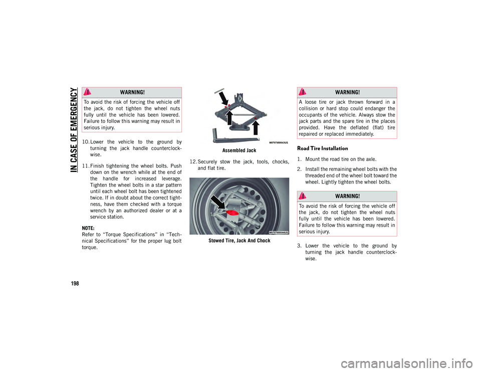
torque. Assembled Jack
12. Securely stow the jack, tools, chocks, and flat tire.
Stowed Tire, Jack And Chock
Road Tire Installation
1. Mount the road tire on the axle.
2. Install the remaining wheel bolts with thethreaded end of the wheel bolt toward the
wheel. Lightly tighten the wheel bolts.
3. Lower the vehicle to the ground by turning the jack handle counterclock -
wise.
WARNING!
To avoid the risk of forcing the vehicle off
the jack, do not tighten the wheel nuts
fully until the vehicle has been lowered.
Failure to follow this warning may result in
serious injury.
WARNING!
A loose tire or jack thrown forward in a
collision or hard stop could endanger the
occupants of the vehicle. Always stow the
jack parts and the spare tire in the places
provided. Have the deflated (flat) tire
repaired or replaced immediately.
WARNING!
To avoid the risk of forcing the vehicle off
the jack, do not tighten the wheel nuts
fully until the vehicle has been lowered.
Failure to follow this warning may result in
serious injury.
2020_JEEP_CHEROKEE_UG_RHD_UK.book Page 198
Page 201 of 332
199
4. Finish tightening the wheel bolts. Pushdown on the wrench while at the end of
the handle for increased leverage.
Tighten the wheel bolts in a star pattern
until each wheel bolt has been tightened
twice. If in doubt about the correct tight -
ness, have them checked with a torque
wrench by an authorized dealer or service
station.
Refer to “Torque Specifications” in
“Technical Specifications” for the proper
lug bolt torque.
5. Lower the jack until it is free. Remove the wheel chocks. Reassemble the lug
wrench to the jack assembly and stow it
in the spare tire area. Secure the
assembly using the means provided.
Release the parking brake before driving
the vehicle.
6. After 25 miles (40 km), check the wheel bolt torque with a torque wrench to
ensure that all wheel bolts are properly
seated against the wheel.Declaration Of Conformance
1. The undersigned, Tony Fabiano, repre -
senting the manufacturer, herewith
declares that the machinery described
below fulfills all relevant provisions of:
The EC-directive 2006/42/EC on
Machinery
2. Description of machinery.
a) Generic Denomination: Vehicle Jack
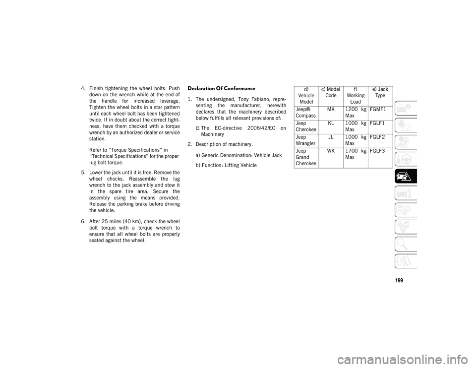
b) Function: Lifting Vehicle d)
Vehicle Model c) Model
Code f)
Working Load e) Jack
Type
Jeep®
Compass MK 1200 kg
Max FGMF1
Jeep
Cherokee KL 1000 kg
Max FGLF1
Jeep
Wrangler JL 1000 kg
Max FGLF2
Jeep
Grand
Cherokee WK 1700 kg
Max FGLF3
2020_JEEP_CHEROKEE_UG_RHD_UK.book Page 199
Page 258 of 332
TECHNICAL SPECIFICATIONS
256
WHEEL AND TIRE TORQUE
SPECIFICATIONS
Proper lug nut/bolt torque is very important
to ensure that the wheel is properly mounted
to the vehicle. Any time a wheel has been
removed and reinstalled on the vehicle, the
lug nuts/bolts should be torqued using a
properly calibrated torque wrench using a
high quality six sided (hex) deep wall socket.
Torque Specifications
**Use only authorized dealer recommended
lug nuts/bolts and clean or remove any dirt or
oil before tightening.
Inspect the wheel mounting surface prior to
mounting the tire and remove any corrosion
or loose particles.
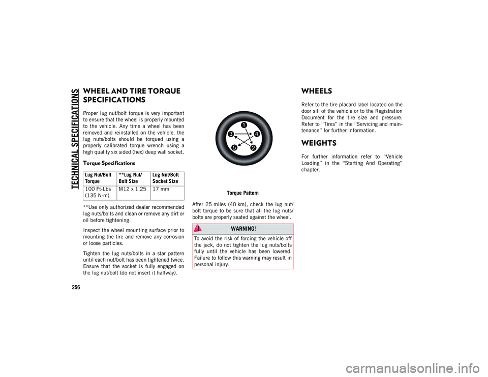
Tighten the lug nuts/bolts in a star pattern
until each nut/bolt has been tightened twice.
Ensure that the socket is fully engaged on
the lug nut/bolt (do not insert it halfway).Torque Pattern
After 25 miles (40 km), check the lug nut/
bolt torque to be sure that all the lug nuts/
bolts are properly seated against the wheel.
WHEELS
Refer to the tire placard label located on the
door sill of the vehicle or to the Registration
Document for the tire size and pressure.
Refer to “Tires” in the “Servicing and main -
tenance” for further information.
WEIGHTS
For further information refer to “Vehicle
Loading” in the “Starting And Operating”
chapter.
Lug Nut/Bolt
Torque **Lug Nut/
Bolt SizeLug Nut/Bolt
Socket Size
100 Ft-Lbs
(135 N·m) M12 x 1.25 17 mm
WARNING!
To avoid the risk of forcing the vehicle off
the jack, do not tighten the lug nuts/bolts
fully until the vehicle has been lowered.
Failure to follow this warning may result in
personal injury.
2020_JEEP_CHEROKEE_UG_RHD_UK.book Page 256
Page 330 of 332
328
INDEX
Pressure Monitoring System (TPMS)....................... 70 , 93
Radial ........................................... 243
Replacement ................................. 245
Rotation ........................................ 250
Safety ........................................... 241
Snow Tires..................................... 246
Spare Tires ............................ 246 , 247
Spinning ....................................... 244
Tread Wear Indicators ..................... 244
Wheel Nut Torque .......................... 256
To Open Hood ..................................... 52
Towing...................................... 179 , 215
Disabled Vehicle ............................ 215 Guide ............................................ 179
Recreational .................................. 180
Weight .......................................... 179
Towing Behind A Motorhome .............. 180
Traction Control ................................... 87
Traction Control Switch ........................ 87
Trailer Sway Control (TSC) .................... 87
Trailer Towing ................................... 179
Trailer Towing Guide .......................... 179
Trailer Weight .................................... 179
Transaxle Automatic...................................... 146
Operation ...................................... 146 Transmission..................................... 147
Automatic ..............................147 , 236
Fluid............................................. 265
Maintenance ................................. 236
Manual ......................................... 143
Transporting Pets .............................. 134
Tread Wear Indicators ........................ 244
Turn Signals ............................ 30 , 33 , 73
U
Uconnect Uconnect Settings ......................... 285
Uconnect 3 With 5-Inch Display ......... 269
Uconnect 4 With 7-Inch Display ......... 272
Uconnect 4 With 8.4-Inch Display ...... 277
Uconnect Phone ................................ 290 Making A Call ................................ 296
Pairing .......................................... 292
Uconnect Settings Customer Programmable Features ...............................19 , 285
Passive Entry Programming ............... 19
Untwisting Procedure, Seat Belt ......... 103
USB ................................................. 286 V
Vehicle Loading .................................177
Vehicle Modifications/Alterations .............4
Vehicle Storage ....................................46
Ventilated Seats ...................................25
Voice Command ......................... 296
, 299
Voice Recognition System (VR) .... 296 , 299
W
Warning Lights (Instrument Cluster
Descriptions) .......................................68
Warnings And Cautions ...........................4
Warnings, Roll Over ................................2
Washers, Windshield ..........................234
Washing Vehicle.................................252
Wheel And Wheel Tire Care .................248
Wheel And Wheel Tire Trim .................248
Wind Buffeting ....................................50
Window Fogging ...................................46
Windows .............................................47 Power ..............................................47
Windshield Defroster ..........................136
Windshield Washers .............................34 Fluid .............................................234
Windshield Wiper Blades ....................237
Windshield Wipers ....................... 34 , 234
Wipers Blade Replacement .................237
Wipers, Intermittent .............................34
Wipers, Rain Sensitive ..........................35
2020_JEEP_CHEROKEE_UG_RHD_UK.book Page 328