start stop button JEEP CHEROKEE 2023 Owner's Manual
[x] Cancel search | Manufacturer: JEEP, Model Year: 2023, Model line: CHEROKEE, Model: JEEP CHEROKEE 2023Pages: 276, PDF Size: 12.55 MB
Page 109 of 276
STARTING AND OPERATING107
Vehicle speed is less than 15 mph (25 km/h).
Vehicle is not in 4WD Low (if equipped).
The outer surface and the underside of the front and
rear fascias/bumpers are clean and clear of snow, ice,
mud, dirt or other obstruction.
When pushed, the LED on the ParkSense Active Park
Assist switch will blink momentarily, and then the LED will
turn off if any of the previously described conditions are
not present.
NOTE:If the vehicle is driven above approximately 15 mph
(25 km/h) while searching for a parking space, the
instrument cluster display will instruct the driver to slow
down. If the vehicle is driven above approximately 18 mph
(30 km/h), the system will cancel. The driver must then
reactivate the system by pushing the ParkSense Active
Park Assist switch.
PARALLEL/PERPENDICULAR PARKING
S
PACE ASSISTANCE OPERATION
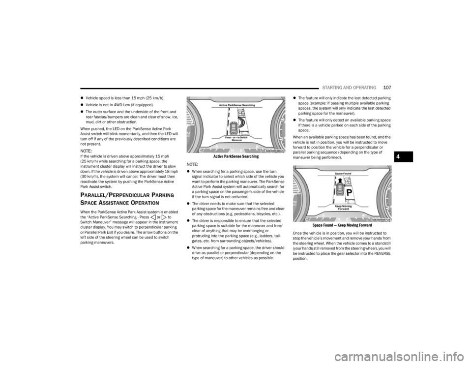
When the ParkSense Active Park Assist system is enabled
the “Active ParkSense Searching - Press or to
Switch Maneuver” message will appear in the instrument
cluster display. You may switch to perpendicular parking
or Parallel Park Exit if you desire. The arrow buttons on the
left side of the steering wheel can be used to switch
parking maneuvers.
Active ParkSense Searching
NOTE:
When searching for a parking space, use the turn
signal indicator to select which side of the vehicle you
want to perform the parking maneuver. The ParkSense
Active Park Assist system will automatically search for
a parking space on the passenger's side of the vehicle
if the turn signal is not activated.
The driver needs to make sure that the selected
parking space for the maneuver remains free and clear
of any obstructions (e.g. pedestrians, bicycles, etc.).
The driver is responsible to ensure that the selected
parking space is suitable for the maneuver and free/
clear of anything that may be overhanging or
protruding into the parking space (e.g., ladders, tail-
gates, etc. from surrounding objects/vehicles).
When searching for a parking space, the driver should
drive as parallel or perpendicular (depending on the
type of maneuver) to other vehicles as possible.
The feature will only indicate the last detected parking
space (example: if passing multiple available parking
spaces, the system will only indicate the last detected
parking space for the maneuver).
The feature will only detect an available parking space
if there is a vehicle parked on each side of the parking
space.
When an available parking space has been found, and the
vehicle is not in position, you will be instructed to move
forward to position the vehicle for a perpendicular or
parallel parking sequence (depending on the type of
maneuver being performed).
Space Found — Keep Moving Forward
Once the vehicle is in position, you will be instructed to
stop the vehicle’s movement and remove your hands from
the steering wheel. When the vehicle comes to a standstill
(your hands still removed from the steering wheel), you will
be instructed to place the gear selector into the REVERSE
position.
4
23_KL_OM_EN_USC_t.book Page 107
Page 124 of 276
122STARTING AND OPERATING
Shifting Into N (NEUTRAL)
Use the following procedure to shift the 4WD system into
N (NEUTRAL).
1. Bring the vehicle to a complete stop on level ground,
and shift the transmission to PARK.
2. Turn the engine off.
3. Turn the ignition to the ON/RUN position, but do not start the engine.
4. Press and hold the brake pedal.
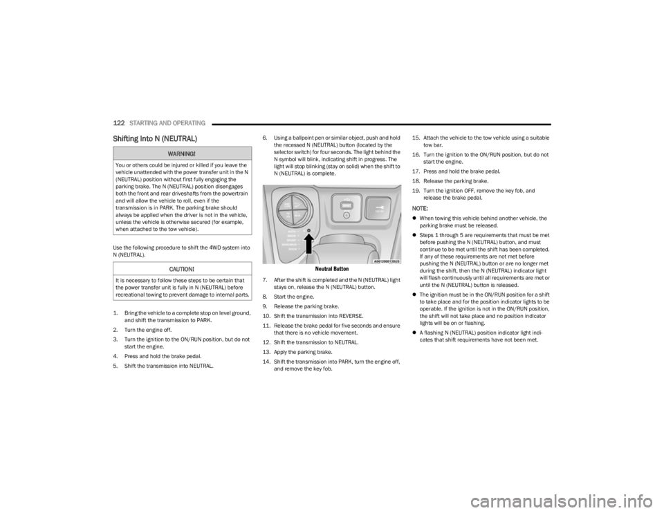
5. Shift the transmission into NEUTRAL. 6. Using a ballpoint pen or similar object, push and hold
the recessed N (NEUTRAL) button (located by the
selector switch) for four seconds. The light behind the
N symbol will blink, indicating shift in progress. The
light will stop blinking (stay on solid) when the shift to
N (NEUTRAL) is complete.
Neutral Button
7. After the shift is completed and the N (NEUTRAL) light stays on, release the N (NEUTRAL) button.
8. Start the engine.
9. Release the parking brake.
10. Shift the transmission into REVERSE.
11. Release the brake pedal for five seconds and ensure that there is no vehicle movement.
12. Shift the transmission to NEUTRAL.
13. Apply the parking brake.
14. Shift the transmission into PARK, turn the engine off, and remove the key fob. 15. Attach the vehicle to the tow vehicle using a suitable
tow bar.
16. Turn the ignition to the ON/RUN position, but do not start the engine.
17. Press and hold the brake pedal.
18. Release the parking brake.
19. Turn the ignition OFF, remove the key fob, and release the brake pedal.
NOTE:
When towing this vehicle behind another vehicle, the
parking brake must be released.
Steps 1 through 5 are requirements that must be met
before pushing the N (NEUTRAL) button, and must
continue to be met until the shift has been completed.
If any of these requirements are not met before
pushing the N (NEUTRAL) button or are no longer met
during the shift, then the N (NEUTRAL) indicator light
will flash continuously until all requirements are met or
until the N (NEUTRAL) button is released.
The ignition must be in the ON/RUN position for a shift
to take place and for the position indicator lights to be
operable. If the ignition is not in the ON/RUN position,
the shift will not take place and no position indicator
lights will be on or flashing.
A flashing N (NEUTRAL) position indicator light indi -
cates that shift requirements have not been met.
WARNING!
You or others could be injured or killed if you leave the
vehicle unattended with the power transfer unit in the N
(NEUTRAL) position without first fully engaging the
parking brake. The N (NEUTRAL) position disengages
both the front and rear driveshafts from the powertrain
and will allow the vehicle to roll, even if the
transmission is in PARK. The parking brake should
always be applied when the driver is not in the vehicle,
unless the vehicle is otherwise secured (for example,
when attached to the tow vehicle).
CAUTION!
It is necessary to follow these steps to be certain that
the power transfer unit is fully in N (NEUTRAL) before
recreational towing to prevent damage to internal parts.
23_KL_OM_EN_USC_t.book Page 122
Page 125 of 276
STARTING AND OPERATING123
Shifting Out Of N (NEUTRAL)
Use the following procedure to prepare your vehicle for
normal use.
1. Bring the vehicle to a complete stop, leaving it
connected to the tow vehicle.
2. Apply the parking brake.
3. Turn the ignition to the ON/RUN position, but do not start the engine.
4. Press and hold the brake pedal.
5. Shift the transmission into NEUTRAL.
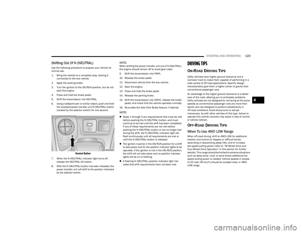
6. Using a ballpoint pen or similar object, push and hold the recessed power transfer unit N (NEUTRAL) button
(located by the selector switch) for one second.
Neutral Button
7. When the N (NEUTRAL) indicator light turns off, release the NEUTRAL (N) button.
8. After the N (NEUTRAL) button has been released, the power transfer unit will shift to the position indicated
by the selector switch.
NOTE:When shifting the power transfer unit out of N (NEUTRAL),
the engine should remain off to avoid gear clash.
9. Shift the transmission into PARK.
10. Release the brake pedal.
11. Disconnect vehicle from the tow vehicle.
12. Start the engine.
13. Press and hold the brake pedal.
14. Release the parking brake.
15. Shift the transmission into DRIVE, release the brake pedal, and check that the vehicle operates normally.
16. Re-enable the Auto Park Brake feature, if desired.
NOTE:
Steps 1 through 5 are requirements that must be met
before pushing the N (NEUTRAL) button, and must
continue to be met until the shift has been completed.
If any of these requirements are not met before
pushing the N (NEUTRAL) button or are no longer met
during the shift, the N (NEUTRAL) indicator light will
flash continuously until all requirements are met or
until the N (NEUTRAL) button is released.
The ignition must be in the ON/RUN position for a shift
to take place and for the position indicator lights to be
operable. If the ignition is not in the ON/RUN position,
the shift will not take place and no position indicator
lights will be on or flashing.
A flashing N (NEUTRAL) position indicator light indi -
cates that shift requirements have not been met.
DRIVING TIPS
ON-ROAD DRIVING TIPS
Utility vehicles have higher ground clearance and a
narrower track to make them capable of performing in a
wide variety of off-road applications. Specific design
characteristics give them a higher center of gravity than
conventional passenger cars.
An advantage of the higher ground clearance is a better
view of the road, allowing you to anticipate problems.
Utility vehicles are not designed for cornering at the same
speeds as conventional passenger cars any more than
sports cars are designed to perform satisfactorily in
off-road conditions. Avoid sharp turns or abrupt
maneuvers. As with other vehicles of this type, failure to
operate this vehicle correctly may result in loss of control
or vehicle rollover.
OFF-ROAD DRIVING TIPS
When To Use 4WD LOW Range
When off-road driving, shift to 4WD LOW for additional
traction and control on slippery or difficult terrain,
ascending or descending steep hills, and to increase
low-speed pulling power (refer to “All Wheel Drive and
Four-Wheel Drive Operation” in this section for further
details). This range should be limited to extreme situations
such as deep snow, mud, or sand where additional low
speed pulling power is needed. Vehicle speeds in excess
of 25 mph (40 km/h) should be avoided when in 4WD LOW range.
4
23_KL_OM_EN_USC_t.book Page 123
Page 148 of 276
146SAFETY
(Continued)
Full Off — If Equipped
This mode is intended for off-highway or off-road use only
and should not be used on any public roadways. In this
mode, TCS and ESC features are turned off. To enter the
“Full Off” mode, push and hold the ESC OFF button for five
seconds while the vehicle is stopped with the engine
running. After five seconds, a chime will sound, the ESC
OFF Indicator Light will illuminate, and the ESC OFF
message will display in the instrument cluster. To turn ESC
on again, momentarily push the ESC OFF button.
NOTE:System may switch from ESC “Full Off” to “Partial Off”
mode when vehicle exceeds a predetermined speed.
When the vehicle speed slows below the predetermined
speed the system will return to ESC “Full Off”.
ESC modes may also be affected by drive modes (if
equipped).ESC Activation/Malfunction Indicator Light
And ESC OFF Indicator Light
The ESC Activation/Malfunction Indicator Light
in the instrument cluster will come on when the
ignition is placed in the ON/RUN mode. It
should turn off with the engine running. If the
ESC Activation/Malfunction Indicator Light comes on
continuously with the engine running, a malfunction has
been detected in the ESC system. If this light remains on
after several ignition cycles, and the vehicle has been
driven several miles (kilometers) at speeds greater than
30 mph (48 km/h), see an authorized dealer as soon as possible to have the problem diagnosed and corrected.
The ESC Activation/Malfunction Indicator Light starts to
flash as soon as the tires lose traction and the ESC system
becomes active. The ESC Activation/Malfunction Indicator
Light also flashes when TCS is active. If the ESC
Activation/Malfunction Indicator Light begins to flash
during acceleration, ease up on the accelerator and apply
as little throttle as possible. Be sure to adapt your speed
and driving to the prevailing road conditions. The ESC OFF Indicator Light indicates that the
Electronic Stability Control (ESC) is in a reduced
mode.
NOTE:
The ESC Activation/Malfunction Indicator Light and the
ESC OFF Indicator Light come on momentarily each
time the ignition is placed in the ON position.
Each time the ignition is placed in the ON position, the
ESC system will be on even if it was turned off previ -
ously.
The ESC system will make buzzing or clicking sounds
when it is active. This is normal; the sounds will stop
when ESC becomes inactive following the maneuver
that caused the ESC activation.
Hill Descent Control (HDC) — If Equipped
HDC is intended for low speed off-road driving while in
4WD Low. HDC maintains vehicle speed while descending
hills during various driving situations. HDC controls vehicle
speed by actively controlling the brakes.
HDC Has Three States:
1. Off (feature is not enabled and will not activate).
2. Enabled (feature is enabled and ready but activation
conditions are not met, or driver is actively overriding
with brake or throttle application).
3. Active (feature is enabled and actively controlling vehicle speed).WARNING!
In the ESC “Full Off” mode, the engine torque reduc -
tion and stability features are disabled. Therefore,
enhanced vehicle stability offered by the ESC system
is unavailable. In an emergency evasive maneuver,
the ESC system will not engage to assist in main -
taining stability. ESC “Full Off” mode is intended for
off-highway or off-road use only.
The Electronic Stability Control (ESC) cannot prevent
the natural laws of physics from acting on the
vehicle, nor can it increase the traction afforded by
prevailing road conditions. ESC cannot prevent all
accidents, including those resulting from excessive
speed in turns, driving on very slippery surfaces, or
hydroplaning. ESC also cannot prevent collisions.
WARNING!
23_KL_OM_EN_USC_t.book Page 146
Page 193 of 276
IN CASE OF EMERGENCY191
The Device Screen will display the following message
“Vehicle device requires service. Please contact an
authorized dealer.”
An In-Vehicle Audio message will state “Vehicle device
requires service. Please contact an authorized dealer.”
Even if the SOS Call system is fully functional, factors
beyond FCA US LLC’s control may prevent or stop the SOS
Call system operation. These include, but are not limited
to, the following factors:
The ignition is in the OFF position
The vehicle’s electrical systems are not intact
The SOS Call system software and/or hardware are
damaged during a crash
The vehicle battery loses power or becomes discon -
nected during a vehicle crash
LTE (voice/data) 4G (data) network and/or Global Posi -
tioning Satellite signals are unavailable or obstructed
Equipment malfunction at the SOS operator facility
Operator error by the SOS operator
LTE (voice/data) 4G (data) network congestion
Weather
Buildings, structures, geographic terrain, or tunnels
NOTE:Changes or modifications not expressly approved by the
party responsible for compliance could void the user's
authority to operate the equipment.
Automatic SOS — If Equipped
Automatic SOS is a hands-free safety service that can
immediately connect you with help in the event that your
vehicle’s airbags deploy. Please refer to your provided
radio supplement for complete information.
ASSIST Call
The ASSIST Button is used to automatically connect you to
any one of the following support centers:
Roadside Assistance – If you get a flat tire, or need a
tow, just push the ASSIST button and you’ll be
connected to someone who can help. Roadside Assis -
tance will know what vehicle you’re driving and its loca -
tion. Additional fees may apply for roadside assistance.
SiriusXM Guardian™ Customer Care – In-vehicle
support for SiriusXM Guardian™.
Vehicle Customer Care – Total support for all other
vehicle issues.
Uconnect Customer Care - Total support for Radio,
Phone and NAV issues.JACKING AND TIRE CHANGING
WARNING!
Ignoring the Rearview Mirror light could mean you
will not have SOS Call services. If the Rearview Mirror
light is illuminated, have an authorized dealer
service the SOS Call system immediately.
The Occupant Restraint Control module turns on the
air bag Warning Light on the instrument panel if a
malfunction in any part of the system is detected. If
the Air Bag Warning Light is illuminated, have an
authorized dealer service the Occupant Restraint
Control system immediately.
CAUTION!
To avoid damage to the mirror during cleaning, never
spray any cleaning solution directly onto the mirror.
Apply the solution onto a clean cloth and wipe the
mirror clean.
WARNING!
Do not attempt to change a tire on the side of the
vehicle close to moving traffic. Pull far enough off the
road to avoid the danger of being hit when operating
the jack or changing the wheel.
Being under a jacked-up vehicle is dangerous. The
vehicle could slip off the jack and fall on you. You
could be crushed. Never put any part of your body
under a vehicle that is on a jack. If you need to get
under a raised vehicle, take it to a service center
where it can be raised on a lift.
Never start or run the engine while the vehicle is on
a jack.
The jack is designed to be used as a tool for changing
tires only. The jack should not be used to lift the
vehicle for service purposes. The vehicle should be
jacked on a firm level surface only. Avoid ice or slip -
pery areas.
7
23_KL_OM_EN_USC_t.book Page 191
Page 200 of 276
198IN CASE OF EMERGENCY
SEALING A TIRE WITH TIRE SERVICE KIT
(A) Whenever You Stop To Use Tire Service
Kit:
1. Pull over to a safe location and turn on the vehicle’s
Hazard Warning Flashers.
2. Verify that the valve stem (on the wheel with the deflated tire) is in a position that is near to the
ground. This will allow the Tire Service Kit Hoses and to reach the valve stem and keep the Tire Service Kit
flat on the ground. This will provide the best
positioning of the kit when injecting the sealant into
the deflated tire and running the air pump. Move the
vehicle as necessary to place the valve stem in this
position before proceeding.
3. Place the transmission in PARK (P) (auto transmission) or in Gear (manual transmission) and
place the ignition in the OFF position.
4. Apply the parking brake.
(B) Setting Up To Use Tire Service Kit:
1. Push in the Mode Select Knob and turn to the Sealant Mode position.
2. Uncoil the Sealant Hose and then remove the cap from the fitting at the end of the hose.
3. Place the Tire Service Kit flat on the ground next to the deflated tire.
4. Remove the cap from the valve stem and then screw the fitting at the end of the Sealant Hose onto the
valve stem.
5. Uncoil the Power Plug and insert the plug into the vehicle’s 12 Volt power outlet.
NOTE:Do not remove foreign objects (e.g., screws or nails) from
the tire.
(C) Injecting Tire Service Kit Sealant Into
The Deflated Tire:
Always start the engine before turning ON the Tire
Service Kit.
NOTE:Manual transmission vehicles must have the parking
brake engaged and the gear selector in NEUTRAL.
After pushing the Power Button, the sealant (white
fluid) will flow from the Sealant Bottle through the
Sealant Hose and into the tire.
NOTE:Sealant may leak out through the puncture in the tire.
If the sealant (white fluid) does not flow within
0 – 10 seconds through the Sealant Hose:
1. Push the Power Button to turn Off the Tire Service
Kit. Disconnect the Sealant Hose from the valve
stem. Make sure the valve stem is free of debris.
Reconnect the Sealant Hose to the valve stem.
Check that the Mode Select Knob is in the Sealant
Mode position and not Air Mode. Push the Power
Button to turn On the Tire Service Kit.
2. Connect the Power Plug to a different 12 Volt power outlet in your vehicle or another vehicle, if available.
Make sure the engine is running before turning ON
the Tire Service Kit.
3. The Sealant Bottle may be empty due to previous use. Call for assistance.
NOTE:If the Mode Select Knob is on Air Mode and the pump is
operating, air will dispense from the Air Pump Hose only,
not the Sealant Hose.
A loose Tire Service Kit thrown forward in a collision
or hard stop could endanger the occupants of the
vehicle. Always stow the Tire Service Kit in the place
provided. Failure to follow these warnings can result
in injuries that are serious or fatal to you, your
passengers, and others around you.
Take care not to allow the contents of Tire Service Kit
to come in contact with hair, eyes, or clothing. Tire
Service Kit sealant is harmful if inhaled, swallowed,
or absorbed through the skin. It causes skin, eye, and
respiratory irritation. Flush immediately with plenty of
water if there is any contact with eyes or skin. Change
clothing as soon as possible, if there is any contact
with clothing.
Tire Service Kit Sealant solution contains latex. In
case of an allergic reaction or rash, consult a physi -
cian immediately. Keep Tire Service Kit out of reach
of children. If swallowed, rinse mouth immediately
with plenty of water and drink plenty of water. Do not
induce vomiting! Consult a physician immediately.
WARNING!
23_KL_OM_EN_USC_t.book Page 198
Page 206 of 276
204IN CASE OF EMERGENCY
6. Move the gear selector to the NEUTRAL (N) position.
7. The vehicle may then be started in NEUTRAL (N).
8. Reinstall the gear selector boot.
FREEING A STUCK VEHICLE
If your vehicle becomes stuck in mud, sand or snow, it can
often be moved using a rocking motion. Turn the steering
wheel right and left to clear the area around the front
wheels. Push and hold the lock button on the gear
selector. Then shift back and forth between DRIVE (D) and
REVERSE (R), while gently pressing the accelerator.
NOTE:Shifts between DRIVE (D) and REVERSE (R) can only be
achieved at wheel speeds of 5 mph (8 km/h) or less.
Whenever the transmission remains in NEUTRAL (N) for
more than two seconds, you must press the brake pedal
to engage DRIVE (D) or REVERSE (R). Use the least amount of accelerator pedal pressure that
will maintain the rocking motion without spinning the
wheels or racing the engine.NOTE:Push the ESC OFF button (if necessary), to place the Elec
-
tronic Stability Control (ESC) system in “Partial Off” mode,
before rocking the vehicle
Úpage 145. Once the vehicle
has been freed, push the ESC OFF button again to restore
“ESC On” mode.
WARNING!
Fast spinning tires can be dangerous. Forces generated
by excessive wheel speeds may cause damage, or even
failure, of the axle and tires. A tire could explode and
injure someone. Do not spin your vehicle's wheels
faster than 30 mph (48 km/h) or for longer than 30
seconds continuously without stopping when you are
stuck and do not let anyone near a spinning wheel, no
matter what the speed.
CAUTION!
Racing the engine or spinning the wheels may lead to
transmission overheating and failure. Allow the
engine to idle with the transmission in NEUTRAL for
at least one minute after every five rocking-motion
cycles. This will minimize overheating and reduce the
risk of clutch or transmission failure during
prolonged efforts to free a stuck vehicle.
When “rocking” a stuck vehicle by shifting between
DRIVE and REVERSE, do not spin the wheels faster
than 15 mph (24 km/h), or drivetrain damage may
result.
Revving the engine or spinning the wheels too fast
may lead to transmission overheating and failure. It
can also damage the tires. Do not spin the wheels
above 30 mph (48 km/h) while in gear (no transmis -
sion shifting occurring).
23_KL_OM_EN_USC_t.book Page 204
Page 270 of 276

268
Remote Sound System (Radio) Control ...................... 140
Remote Starting
Exit Remote Start Mode ............................................18
Uconnect Customer Programmable Features .........19
Uconnect Settings...................................................... 19
Remote Starting System.................................................18
Replacement Keys ..........................................................15 Replacement Tires ....................................................... 243
Reporting Safety Defects............................................. 261
Restraints, Child ........................................................... 176
Restraints, Head ............................................................. 32
Roll Over Warning ............................................................. 8
Roof Type Carrier ............................................................60
Rotation, Tires .............................................................. 248
SSafety Checks Inside Vehicle ...................................... 187
Safety Checks Outside Vehicle ................................... 188
Safety Defects, Reporting............................................ 261
Safety Information, Tire ............................................... 235
Safety Tips .................................................................... 186
Schedule, Maintenance............................................... 208
Seat Belt Reminder.........................................................68 Seat Belts ............................................................ 159
, 187
Adjustable Shoulder Belt........................................ 162
Adjustable Upper Shoulder Anchorage ................. 162
Adjustable Upper Shoulder Belt Anchorage.......... 162
Automatic Locking Retractor (ALR)........................ 165
Child Restraints ...................................................... 176
Energy Management Feature ................................ 165
Extender .................................................................. 164
Front Seat..............................................159
, 160, 161
Inspection................................................................ 187 Lap/Shoulder Belt Operation ................................. 161
Lap/Shoulder Belt Untwisting ................................ 162
Lap/Shoulder Belts ................................................. 160
Operating Instructions............................................. 161Pregnant Women..................................................... 165Pretensioners .......................................................... 165
Rear Seat ................................................................. 160
Reminder ................................................................. 159
Seat Belt Extender...................................................164
Seat Belt Pretensioner ............................................165
Untwisting Procedure .............................................. 162
Seat Belts Maintenance ............................................... 251
Seats................................................................................ 28 Adjustment.......................................................... 28
, 30
Easy Entry .................................................................. 31
Head Restraints......................................................... 32
Heated........................................................................ 31
Memory ...................................................................... 26
Rear Folding............................................................... 28
Tilting .......................................................................... 28
Vented ........................................................................ 32
Ventilated ................................................................... 32
Security Alarm .......................................................... 20
, 70
Arm The System......................................................... 20
Disarm The System ................................................... 20
Selec-Terrain ................................................................... 88 Sentry Key (Immobilizer) ................................................ 16
Sentry Key Replacement................................................ 15
Service Assistance........................................................ 258
Service Contract ...........................................................260
Service Manuals ...........................................................261
Settings ......................................................................... 126
Shift Lever Override ...................................................... 203 Shifting
Automatic Transmission ........................................... 81
Power Transfer Unit, Shifting Into PowerTransfer Unit Neutral (N) ..........................122
, 123
Transfer Case, Shifting Into Transfer Case Neutral (N) .......................................................... 122
Transfer Case, Shifting Out Of Transfer Case Neutral (N) .......................................................... 123
Shoulder Belts .............................................................. 160
Side Distance Warning System ................................... 104
Side View Mirror Adjustment ......................................... 34 Signals, Turn .......................................................... 74
, 188
Snow Chains (Tire Chains) ........................................... 246
Snow Tires .................................................................... 244
Spare Tires ...........................................................244
, 245
Speed Control Cancel ........................................................................ 92
Resume...................................................................... 91
Starting............................................................................ 77 Button ........................................................................ 16
Cold Weather............................................................. 77
Engine Fails To Start ................................................. 78
Remote ...................................................................... 18
Starting Procedures ....................................................... 77 Steering Tilt Column................................................................. 24
Wheel, Heated .................................................... 24
, 25
Steering Wheel Audio Controls .................................... 140
Steering Wheel Mounted Sound System Controls ..... 140
Stop/Start ................................................................ 74
, 89
Storage ..................................................................... 49, 50
Console ...................................................................... 50
Storage Compartment, Center Seat.............................. 50
Storage, Vehicle..................................................... 48
, 250
23_KL_OM_EN_USC_t.book Page 268