clock JEEP CHEROKEE 2023 Owners Manual
[x] Cancel search | Manufacturer: JEEP, Model Year: 2023, Model line: CHEROKEE, Model: JEEP CHEROKEE 2023Pages: 276, PDF Size: 12.55 MB
Page 36 of 276
34GETTING TO KNOW YOUR VEHICLE
MIRRORS
INSIDE REARVIEW MIRROR
Auto Dimming Mirror
A single ball joint mirror is provided in the vehicle. It is a
twist on mirror that has a fixed position at the windshield.
The mirror installs on the windshield button with a
counterclockwise rotation and requires no tools for
mounting. The rearview mirror can be adjusted up, down,
left, and right. The mirror should be adjusted to center on
the view through the rear window.
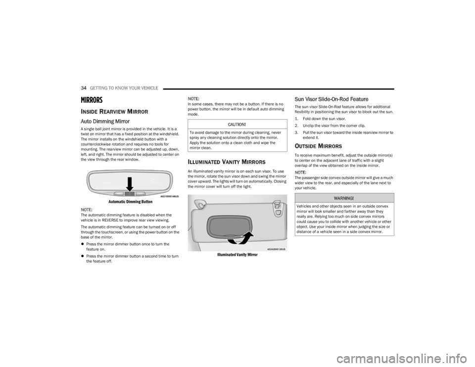
Automatic Dimming Button
NOTE:
The automatic dimming feature is disabled when the
vehicle is in REVERSE to improve rear view viewing.
The automatic dimming feature can be turned on or off
through the touchscreen, or using the power button on the
base of the mirror.
Press the mirror dimmer button once to turn the
feature on.
Press the mirror dimmer button a second time to turn
the feature off.
NOTE:In some cases, there may not be a button. If there is no
power button, the mirror will be in default auto dimming
mode.
ILLUMINATED VANITY MIRRORS
An illuminated vanity mirror is on each sun visor. To use
the mirror, rotate the sun visor down and swing the mirror
cover upward. The lights will turn on automatically. Closing
the mirror cover will turn off the light.
Illuminated Vanity Mirror
Sun Visor Slide-On-Rod Feature
The sun visor Slide-On-Rod feature allows for additional
flexibility in positioning the sun visor to block out the sun.
1. Fold down the sun visor.
2. Unclip the visor from the corner clip.
3. Pull the sun visor toward the inside rearview mirror to
extend it.
OUTSIDE MIRRORS
To receive maximum benefit, adjust the outside mirror(s)
to center on the adjacent lane of traffic with a slight
overlap of the view obtained on the inside mirror.
NOTE:The passenger side convex outside mirror will give a much
wider view to the rear, and especially of the lane next to
your vehicle.
CAUTION!
To avoid damage to the mirror during cleaning, never
spray any cleaning solution directly onto the mirror.
Apply the solution onto a clean cloth and wipe the
mirror clean.
WARNING!
Vehicles and other objects seen in an outside convex
mirror will look smaller and farther away than they
really are. Relying too much on side convex mirrors
could cause you to collide with another vehicle or other
object. Use your inside mirror when judging the size or
distance of a vehicle seen in a side convex mirror.
23_KL_OM_EN_USC_t.book Page 34
Page 41 of 276
GETTING TO KNOW YOUR VEHICLE39
EXTERIOR LIGHTS
MULTIFUNCTION LEVER
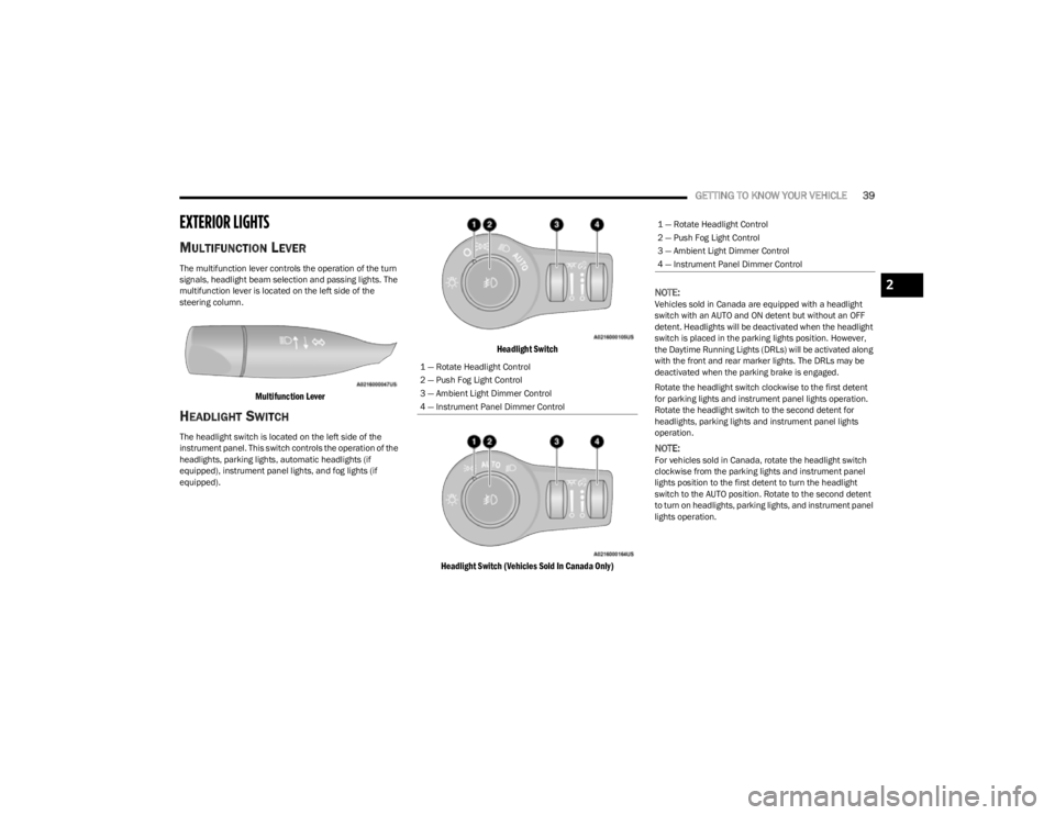
The multifunction lever controls the operation of the turn
signals, headlight beam selection and passing lights. The
multifunction lever is located on the left side of the
steering column.
Multifunction Lever
HEADLIGHT SWITCH
The headlight switch is located on the left side of the
instrument panel. This switch controls the operation of the
headlights, parking lights, automatic headlights (if
equipped), instrument panel lights, and fog lights (if
equipped).
Headlight Switch
Headlight Switch (Vehicles Sold In Canada Only)
NOTE:
Vehicles sold in Canada are equipped with a headlight
switch with an AUTO and ON detent but without an OFF
detent. Headlights will be deactivated when the headlight
switch is placed in the parking lights position. However,
the Daytime Running Lights (DRLs) will be activated along
with the front and rear marker lights. The DRLs may be
deactivated when the parking brake is engaged.
Rotate the headlight switch clockwise to the first detent
for parking lights and instrument panel lights operation.
Rotate the headlight switch to the second detent for
headlights, parking lights and instrument panel lights
operation.
NOTE:For vehicles sold in Canada, rotate the headlight switch
clockwise from the parking lights and instrument panel
lights position to the first detent to turn the headlight
switch to the AUTO position. Rotate to the second detent
to turn on headlights, parking lights, and instrument panel
lights operation.
1 — Rotate Headlight Control
2 — Push Fog Light Control
3 — Ambient Light Dimmer Control
4 — Instrument Panel Dimmer Control
1 — Rotate Headlight Control
2 — Push Fog Light Control
3 — Ambient Light Dimmer Control
4 — Instrument Panel Dimmer Control
2
23_KL_OM_EN_USC_t.book Page 39
Page 42 of 276
40GETTING TO KNOW YOUR VEHICLE
DAYTIME RUNNING LIGHTS (DRLS) —
I
F EQUIPPED
The Daytime Running Lights will turn on when the engine
is started and remain on unless the headlamps are turned
on, the parking brake is applied, or the ignition is placed in
the OFF position.
NOTE:
For vehicles sold in Canada, the Daytime Running
Lights will automatically deactivate when the front fog
lights are turned on.
If allowed by law in the country in which the vehicle was
purchased, the Daytime Running Lights can be turned
on and off using the Uconnect system
Úpage 126.
On some vehicles, the Daytime Running Lights may
deactivate, or reduce intensity, on one side of the
vehicle (when a turn signal is activated on that side), or
on both sides of the vehicle (when the hazard warning
lights are activated).
HIGH/LOW BEAM SWITCH
After the low beam headlights are turned on, push the
multifunction lever, located on the left side of the steering
wheel, away from you to switch the headlights to high
beam. Pulling the multifunction lever back will turn the low
beams on.
AUTOMATIC HIGH BEAM HEADLAMP
C
ONTROL — IF EQUIPPED
The Automatic High Beam Headlamp Control system
provides increased forward lighting at night by automatically controlling the high beams through the use
of a camera mounted on the windshield. This camera
detects vehicle specific light and automatically switches
from high beams to low beams until the approaching
vehicle is out of view.
NOTE:
The Automatic High Beam Headlamp Control is
enabled through the Uconnect system Úpage 126.
The multifunction lever must be in the high beam posi -
tion and the low beams must be turned on in order to
activate the Automatic High Beams.
Broken, muddy, or obstructed headlights and taillights
of vehicles in the field of view will cause headlights to
remain on longer (closer to the vehicle). Also, dirt, film,
and other obstructions on the windshield or camera
lens will cause the system to function improperly.
When set to AUTO, and the low beams are on and the
multifunction lever is in the high beam position, the
system automatically turns the high beams on or off
based on light levels of the approaching vehicles.
Vehicle speed must be greater than 22 mph (35 km/h)
to activate Automatic High Beams. Once activated,
Automatic High Beams will remain on until the speed
falls below 15 mph (25 km/h).
FLASH-TO-PASS
You can signal another vehicle with your headlights by
lightly pulling the multifunction lever toward you. This will
cause the high beam headlights to turn on, and remain on,
until the lever is released.
AUTOMATIC HEADLIGHTS — IF EQUIPPED
This system automatically turns the headlights on or off
according to ambient light levels. To turn the system on,
rotate the headlight switch to the AUTO position for
automatic headlight operation. When the system is on, the
headlight time delay feature is also on. This means the
headlights will stay on for up to 90 seconds (depending on
customer programmable time of 30, 60, or 90 seconds)
after you place the ignition in the OFF position. To turn the
automatic system off, move the headlight switch out of the
AUTO position.
NOTE:The engine must be running before the headlights will
come on in the automatic mode.
PARKING LIGHTS
Rotate the headlight switch clockwise to the first detent
for parking lights and instrument panel lights operation.
Rotate the headlight switch to the second detent for
headlights, parking lights and instrument panel lights
operation.
NOTE:Vehicles sold in Canada are equipped with a headlight
switch with an AUTO and ON detent but without an OFF
detent. Headlights will be deactivated when the headlight
switch is placed in the parking lights position. However,
the Daytime Running Lights (DRLs) will be activated along
with the front and rear marker lights. The DRLs may be
deactivated when the parking brake is engaged.
23_KL_OM_EN_USC_t.book Page 40
Page 49 of 276
GETTING TO KNOW YOUR VEHICLE47
Driver And Passenger Temperature Up And
Down Buttons
These buttons provide the driver and
passenger with independent temperature
control.
Push the red button on the faceplate or
touchscreen or press and slide the
temperature bar towards the red arrow button
on the touchscreen for warmer temperature
settings.
Push the blue button on the faceplate or
touchscreen or press and slide the
temperature bar towards the blue arrow button
on the touchscreen for cooler temperature
settings.
NOTE:The numbers within the temperature display will only
appear if the system is equipped with an automatic
climate control system.
SYNC Button
Press the SYNC button on the touchscreen to
toggle the SYNC feature on/off. The SYNC
indicator illuminates when SYNC is on. SYNC
synchronizes the passenger temperature
setting with the driver temperature setting. Changing the
passenger’s temperature setting while in SYNC will
automatically exit this feature.
NOTE:The SYNC button is only available on the touchscreen.
Blower Control
Blower Control regulates the amount of air
forced through the climate control system.
There are seven blower speeds available.
Adjusting the blower will cause automatic
mode to switch to manual operation. The speeds can be
selected using either the blower control knob on the
faceplate or the buttons on the touchscreen.
Faceplate
The blower speed increases as you turn the blower control
knob clockwise from the lowest blower setting. The blower
speed decreases as you turn the blower control knob
counterclockwise.
Touchscreen
Use the small blower icon to reduce the blower setting and
the large blower icon to increase the blower setting.
Blower can also be selected by pressing the blower bar
area between the icons.
Mode Control
Select Mode by pressing one of the Mode
buttons on the touchscreen to change the
airflow distribution mode. The airflow
distribution mode can be adjusted so air comes
from the instrument panel outlets, floor outlets, defrost
outlets, and demist outlets.
Panel Mode
Air comes from the outlets in the instrument
panel. Each of these outlets can be individually
adjusted to direct the flow of air. The air vanes
of the center outlets and outboard outlets can
be moved up and down or side to side to regulate airflow direction. There is a shut-off wheel located below the air
vanes to shut off or adjust the amount of airflow from
these outlets.
Bi-Level Mode
Air comes from the instrument panel outlets
and floor outlets. A slight amount of air is
directed through the defrost and side window
demister outlets.
NOTE:Bi-Level mode is designed under comfort conditions to
provide cooler air out of the panel outlets and warmer air
from the floor outlets.
Floor Mode
Air comes from the floor outlets. A slight
amount of air is directed through the defrost
and side window demister outlets.
Mix Mode
Air is directed through the floor, defrost, and
side window demister outlets. This setting
works best in cold or snowy conditions that
require extra heat to the windshield. This
setting is good for maintaining comfort while reducing
moisture on the windshield.
Climate Control OFF Button
Press and release the OFF button on the
touchscreen, or push the OFF button on the
faceplate to turn the Climate Control ON/OFF.
2
23_KL_OM_EN_USC_t.book Page 47
Page 132 of 276
130MULTIMEDIA
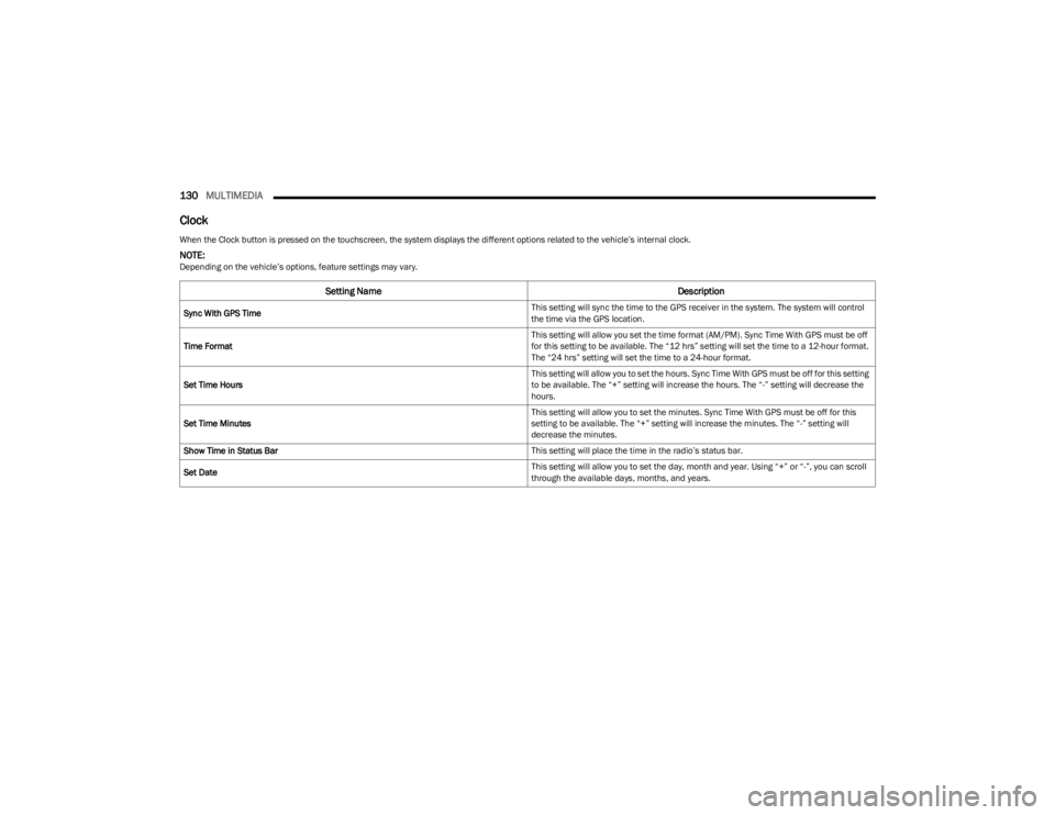
Clock
When the Clock button is pressed on the touchscreen, the system displays the different options related to the vehicle’s internal clock.
NOTE:Depending on the vehicle’s options, feature settings may vary.
Setting Name Description
Sync With GPS Time This setting will sync the time to the GPS receiver in the system. The system will control
the time via the GPS location.
Time Format This setting will allow you set the time format (AM/PM). Sync Time With GPS must be off
for this setting to be available. The “12 hrs” setting will set the time to a 12-hour format.
The “24 hrs” setting will set the time to a 24-hour format.
Set Time Hours This setting will allow you to set the hours. Sync Time With GPS must be off for this setting
to be available. The “+” setting will increase the hours. The “-” setting will decrease the
hours.
Set Time Minutes This setting will allow you to set the minutes. Sync Time With GPS must be off for this
setting to be available. The “+” setting will increase the minutes. The “-” setting will
decrease the minutes.
Show Time in Status Bar This setting will place the time in the radio’s status bar.
Set Date This setting will allow you to set the day, month and year. Using “+” or “-”, you can scroll
through the available days, months, and years.
23_KL_OM_EN_USC_t.book Page 130
Page 142 of 276
140MULTIMEDIA
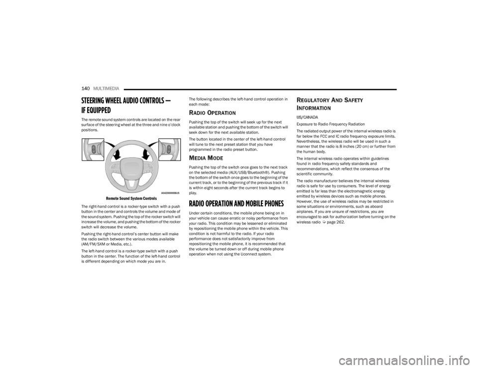
STEERING WHEEL AUDIO CONTROLS —
IF EQUIPPED
The remote sound system controls are located on the rear
surface of the steering wheel at the three and nine o’clock
positions.
Remote Sound System Controls
The right-hand control is a rocker-type switch with a push
button in the center and controls the volume and mode of
the sound system. Pushing the top of the rocker switch will
increase the volume, and pushing the bottom of the rocker
switch will decrease the volume.
Pushing the right-hand control’s center button will make
the radio switch between the various modes available
(AM/FM/SXM or Media, etc.).
The left-hand control is a rocker-type switch with a push
button in the center. The function of the left-hand control
is different depending on which mode you are in. The following describes the left-hand control operation in
each mode:
RADIO OPERATION
Pushing the top of the switch will seek up for the next
available station and pushing the bottom of the switch will
seek down for the next available station.
The button located in the center of the left-hand control
will tune to the next preset station that you have
programmed in the radio preset button.
MEDIA MODE
Pushing the top of the switch once goes to the next track
on the selected media (AUX/USB/Bluetooth®). Pushing
the bottom of the switch once goes to the beginning of the
current track, or to the beginning of the previous track if it
is within eight seconds after the current track begins to
play.
RADIO OPERATION AND MOBILE PHONES
Under certain conditions, the mobile phone being on in
your vehicle can cause erratic or noisy performance from
your radio. This condition may be lessened or eliminated
by repositioning the mobile phone within the vehicle. This
condition is not harmful to the radio. If your radio
performance does not satisfactorily improve from
repositioning the mobile phone, it is recommended that
the volume be turned down or off during mobile phone
operation when not using the Uconnect system.
REGULATORY AND SAFETY
I
NFORMATION
US/CANADA
Exposure to Radio Frequency Radiation
The radiated output power of the internal wireless radio is
far below the FCC and IC radio frequency exposure limits.
Nevertheless, the wireless radio will be used in such a
manner that the radio is 8 inches (20 cm) or further from
the human body.
The internal wireless radio operates within guidelines
found in radio frequency safety standards and
recommendations, which reflect the consensus of the
scientific community.
The radio manufacturer believes the internal wireless
radio is safe for use by consumers. The level of energy
emitted is far less than the electromagnetic energy
emitted by wireless devices such as mobile phones.
However, the use of wireless radios may be restricted in
some situations or environments, such as aboard
airplanes. If you are unsure of restrictions, you are
encouraged to ask for authorization before turning on the
wireless radio
Úpage 262.
23_KL_OM_EN_USC_t.book Page 140
Page 196 of 276
194IN CASE OF EMERGENCY
3. Before raising the vehicle, use the wheel bolt wrench
to loosen, but not remove, the wheel bolts on the
wheel with the flat tire. Turn the wheel bolts counter -
clockwise one turn while the wheel is still on the
ground.
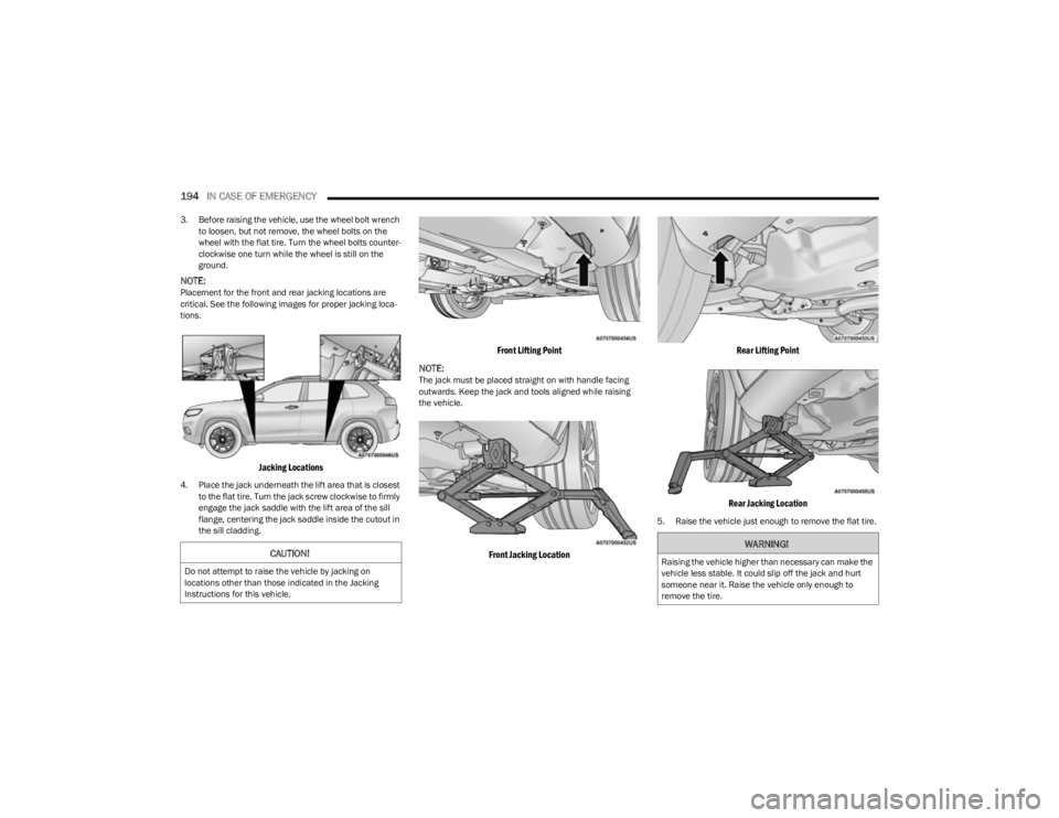
NOTE:Placement for the front and rear jacking locations are
critical. See the following images for proper jacking loca -
tions.
Jacking Locations
4. Place the jack underneath the lift area that is closest to the flat tire. Turn the jack screw clockwise to firmly
engage the jack saddle with the lift area of the sill
flange, centering the jack saddle inside the cutout in
the sill cladding.
Front Lifting Point
NOTE:
The jack must be placed straight on with handle facing
outwards. Keep the jack and tools aligned while raising
the vehicle.
Front Jacking Location Rear Lifting Point
Rear Jacking Location
5. Raise the vehicle just enough to remove the flat tire.
CAUTION!
Do not attempt to raise the vehicle by jacking on
locations other than those indicated in the Jacking
Instructions for this vehicle.
WARNING!
Raising the vehicle higher than necessary can make the
vehicle less stable. It could slip off the jack and hurt
someone near it. Raise the vehicle only enough to
remove the tire.
23_KL_OM_EN_USC_t.book Page 194
Page 197 of 276
IN CASE OF EMERGENCY195
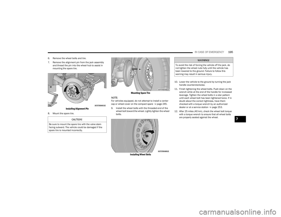
6. Remove the wheel bolts and tire.
7. Remove the alignment pin from the jack assembly
and thread the pin into the wheel hub to assist in
mounting the spare tire.
Installing Alignment Pin
8. Mount the spare tire.
Mounting Spare Tire
NOTE:
For vehicles equipped, do not attempt to install a center
cap or wheel cover on the compact spare Úpage 245.
9. Install the wheel bolts with the threaded end of the wheel bolt toward the wheel. Lightly tighten the wheel
bolts.
Installing Wheel Bolts
10. Lower the vehicle to the ground by turning the jack handle counterclockwise.
11. Finish tightening the wheel bolts. Push down on the wrench while at the end of the handle for increased
leverage. Tighten the wheel bolts in a star pattern
until each wheel bolt has been tightened twice. If in
doubt about the correct tightness, have them
checked with a torque wrench by an authorized
dealer or at a service station
Úpage 253.
12. After 25 miles (40 km), check the wheel bolt torque with a torque wrench to ensure that all wheel bolts
are properly seated against the wheel.
CAUTION!
Be sure to mount the spare tire with the valve stem
facing outward. The vehicle could be damaged if the
spare tire is mounted incorrectly.
WARNING!
To avoid the risk of forcing the vehicle off the jack, do
not tighten the wheel nuts fully until the vehicle has
been lowered to the ground. Failure to follow this
warning may result in serious injury.
7
23_KL_OM_EN_USC_t.book Page 195
Page 236 of 276
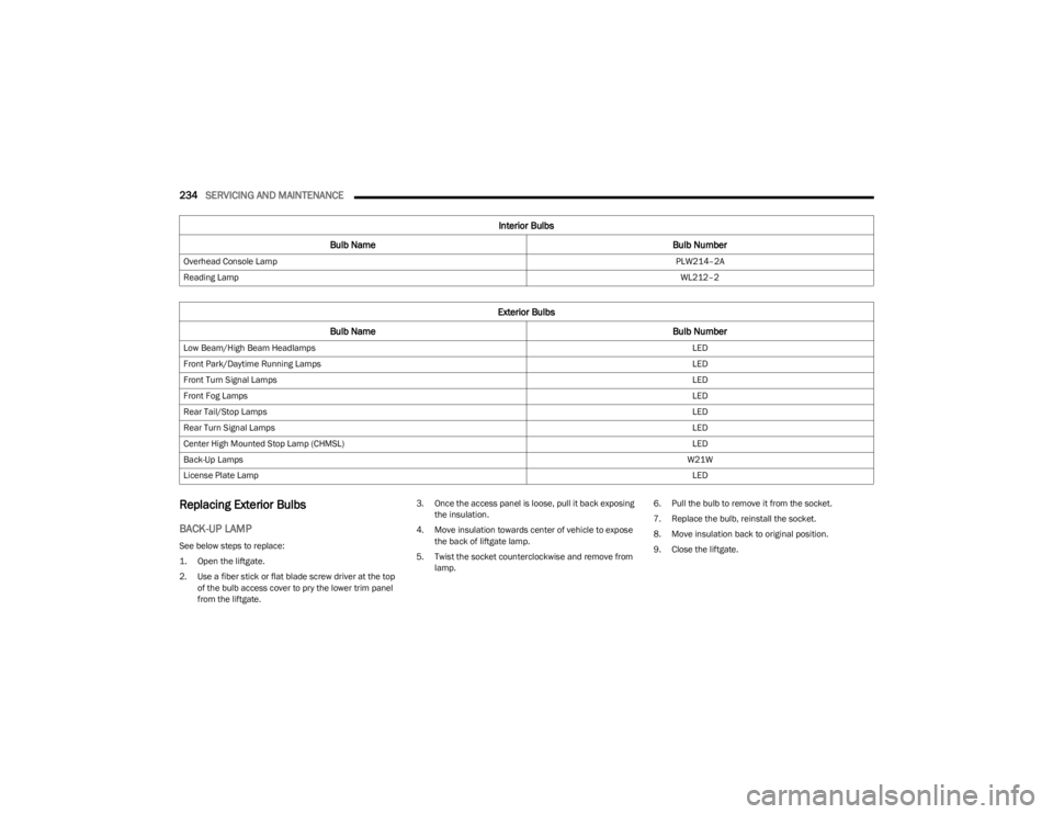
234SERVICING AND MAINTENANCE
Replacing Exterior Bulbs
BACK-UP LAMP
See below steps to replace:
1. Open the liftgate.
2. Use a fiber stick or flat blade screw driver at the top
of the bulb access cover to pry the lower trim panel
from the liftgate. 3. Once the access panel is loose, pull it back exposing
the insulation.
4. Move insulation towards center of vehicle to expose the back of liftgate lamp.
5. Twist the socket counterclockwise and remove from lamp. 6. Pull the bulb to remove it from the socket.
7. Replace the bulb, reinstall the socket.
8. Move insulation back to original position.
9. Close the liftgate.
Overhead Console Lamp
PLW214–2A
Reading Lamp WL212–2
Exterior Bulbs
Bulb Name Bulb Number
Low Beam/High Beam Headlamps LED
Front Park/Daytime Running Lamps LED
Front Turn Signal Lamps LED
Front Fog Lamps LED
Rear Tail/Stop Lamps LED
Rear Turn Signal Lamps LED
Center High Mounted Stop Lamp (CHMSL) LED
Back-Up Lamps W21W
License Plate Lamp LED
Interior Bulbs
Bulb Name Bulb Number
23_KL_OM_EN_USC_t.book Page 234