service indicator JEEP CJ 1953 User Guide
[x] Cancel search | Manufacturer: JEEP, Model Year: 1953, Model line: CJ, Model: JEEP CJ 1953Pages: 376, PDF Size: 19.96 MB
Page 86 of 376
Dl
DAUNTLESS
V-6
ENGINE
Dl-38.
Crankshaft
Cleaning
Clean
the crankshaft thoroughly with a suitable
cleaning solvent.
Clean
drilled oil
passages
in its
journals
with a small rifle brush to remove all
sludge
or gum deposits; dry
passages
with com
pressed air.
Dl-39.
Crankshaft
Inspection
and
Repair
If
the crankshaft has not
been
removed from the
cylinder
block for inspection, disconnect two con necting rods at a time from crankshaft. Inspect
the bearings and crankpin journals. While turning
crankshaft,
it is necessary to temporarily reconnect
the rods to crankshaft to avoid possibility of dam aging the journals through contact with uncon
nected rods.
Inspect the crankpins visually for excessive or ir
regular
wear, and for scoring. Use an
outside
micrometer to check crankpins for out-of-round.
Standard
crankpin
diameter is
2.0000"
[5,080
cm.].
If
crankpins are more than .0015"
[0,0381
mm.]
out-of-round, new bearings cannot be
expected
to
have satisfactory life.
If
the crankshaft has
been
removed from the
cyl
inder
block for inspection support it on V-blocks
at its main bearing journals 1 and 4. Inspect the
main
bearing journals visually for excessive or ir
regular
wear, and for scoring. Standard main bear
ing
journal
diameter is 2.4995"
[6,349
cm.].
Total
indicator readings at each
journal
should not ex
ceed .003"
[0,076
mm.].
Check
run out at all four journals and
note
high
spot
(maximum eccentricity) of each
journal.
High
spot
of each
journal
should
come
at the same
angular
location. If high
spots
do not coincide,
crankshaft
is misaligned and unsatisfactory for
service.
If
crankpin or main bearing journals are scored,
ridged, or out-of-round, the crankshaft must be replaced or reground to a standard undersize bear
ing diameter to ensure satisfactory life of bearings. Slight roughness can be removed with a fine grit
polishing cloth thoroughly
wetted
with
engine
oil.
Burrs
can
be
honed with a fine oil
stone,
so long as
bearing clearances
will
remain within specified
limits.
Dl-40.
Crankshaft
Main
Bearings
A
crankshaft bearing consists of two halves which
are
neither alike nor interchangeable. One half is
carried
in the corresponding main bearing cap; the
other half is located
between
the crankshaft and
cylinder
block. The upper (cylinder block) half
of the bearing is grooved to supply oil to the con necting rod bearings, while the lower (bearing cap)
half
of the bearing is not grooved. The two bearing
halves must not be interchanged. All crankshaft
bearings
except
the thrust bearing and the
rear
main
bearing are identical. The thrust bearing (No. 2) is longer and it is flanged to take
crank
shaft end thrust. When the bearing halves are
placed in cylinder block and bearing cap, the
ends
extend slightly beyond the parting surfaces. When
cap
bolts
are tightened, the halves are clamped
tightly in place to ensure positive seating and to
prevent turning. The
ends
of bearing halves must never be filed flush with parting surface of
crank
case or bearing cap.
Crankshaft
bearings are the precision type which
do not require reaming to size or other fitting.
Shims
are not provided for adjustment since worn
bearings are readily replaced with new bearings of proper size. Bearings for service replacement are
furnished
in standard size and undersizes. Under no circumstances should crankshaft bearing caps
be filed to adjust for wear in old bearings.
Dl-41.
Crankshaft
Main
Bearing
Cleaning
and
Inspection
Clean
main bearing surfaces. Inspect the bearings
visually
for excessive or uneven wear, scoring, and
flaking.
Visibly worn or damaged bearings must
be replaced. It is necessary to check
radial
clear ance of each new or used crankshaft main bearing
before installation.
This
can be
done
by either of two methods, which are described in
Pars.
Dl-42
and
Dl-43.
a.
The desired
radial
clearance of a new bearing
is .0005" to .0021"
[0,0127
a
0,0534
mm.].
b. Replacement bearings are furnished in standard
size, and in several undersizes, including undersizes
for reground journals. If a new bearing is to be installed, try a standard size; then try each under
size in turn until one is found that
meets
the
specified clearance limits.
Note:
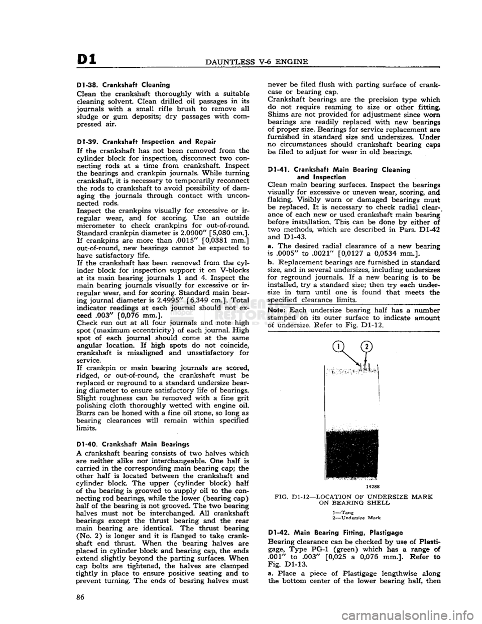
Each
undersize bearing half has a number
stamped on its outer surface to indicate amount of undersize. Refer to Fig. Dl-12. 14288
FIG.
Dl-12—LOCATION
OF
UNDERSIZE
MARK
ON
BEARING
SHELL
1—
Tang
2—
Undersize
Mark
Dl-42.
Main
Bearing
Fitting,
Plastigage
Bearing
clearance can be checked by use of Plasti
gage,
Type PG-1 (green) which has a range of
.001" to .003" [0,025 a
0,076
mm.]. Refer to
Fig.
Dl-13.
a.
Place a piece of Plastigage lengthwise along the
bottom
center of the lower bearing half, then 86
Page 99 of 376
'Jeep'
UNIVERSAL SERIES SERVICE
MANUAL
Dl
both are clean. Any foreign material on either of
these
surfaces
will
cause flywheel run out and en
gine
vibration. Position flywheel to crankshaft and
secure with six mounting bolts. Torque mounting
bolts
50 to 65 lb-ft. [6,91 a 8,98 kg-m.].
Note:
Flywheel mounting
bolts
are unevenly
spaced so that flywheel can be installed in only
one position.
This
assures correct balance of fly
wheel and crankshaft.
b.
Mount a
dial
indicator on flywheel housing
flange of cylinder block and index its plunger to
the flywheel surface. Measure flywheel run out.
Maximum
allowable run out is .015"
[0,381
mm.].
Dl-82.
Install
Cylinder
Head Assembly
Refer
to Fig. Dl-9.
a.
Wipe cylinder head face of
engine
cylinder
block, and be certain no foreign material has fallen
into the cylinder bores, bolt holes, or in the valve
lifter
area.
It is
good
practice to clean out bolt
holes
with compressed air.
b.
Install
a new cylinder head gasket on the
cylin
der
block. Dowels in the block
will
hold the gasket
in
position. Always handle gaskets carefully to
avoid
kinking or damage to the surface treatment
of the gasket. Apply Perfect Seal Aerosol
Spray
Sealer
Part
No.
994757
on cylinder head gaskets.
Dl-79.
Install
Clutch
and Flywheel Housing
a.
Note
marks made on clutch assembly and fly
wheel during
engine
disassembly. Position clutch
assembly to flywheel, according to
marks,
and
fasten
loosely
with six attaching bolts. Torque
bolts
in rotation, one
turn
at a time, to 30 to 40 lb-ft. [4,1 a 5,5 kg-m.].
b.
Engage fork of clutch linkage to clutch and
position flywheel housing to
engine
cylinder block.
Secure
housing to block with six mounting bolts.
Torque
bolts
30 to 40 lb-ft. [4,1 a 5,5 kg-m.].
D1-80.
Install
Camshaft
Insert
camshaft into camshaft bearings of
engine
cylinder
block carefully to avoid damage to bear
ing surfaces. Make certain camshaft journals are
properly
seated in bearings.
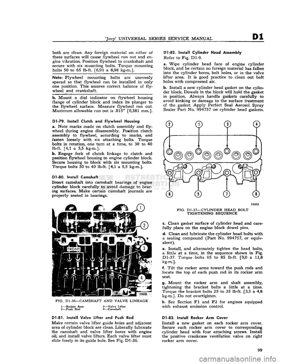
12695
FIG.
D1-36—CAMSHAFT
AND
VALVE LINKAGE
1—
Rocker
Arm
2—
Push
Rod 3—
Valve
Lifter
4—
Camshaft
14203
FIG.
Dl-37—CYLINDER
HEAD
BOLT TIGHTENING SEQUENCE c.
Clean
gasket surface of cylinder head and care
fully
place on the
engine
block dowel pins.
d.
Clean
and lubricate the cylinder head
bolts
with
a
sealing compound
(Part
No. 994757, or equiv
alent).
e.
Install,
and alternately tighten the head bolts,
a
little at a time, in the sequence shown in Fig.
Dl-37.
Torque
bolts
65 to 85 lb-ft. [9,0 a 11,8
kg-m.].
f.
Tilt
the rocker arms toward the push rods and locate the top of each push rod in its rocker arm
seat.
g.
Mount the rocker arm and shaft assembly, tightening the bracket
bolts
a little at a time.
Torque
the bracket
bolts
25 to 35 lb-ft. [3,5 a 4,8
kg-m.].
Do not overtighten.
h.
See Section Fl and F2 for
engines
equipped
with
exhaust emission control.
D1-81.
Install
Valve Lifter
and Push Rod
Make
certain valve lifter guide
holes
and adjacent
area
of cylinder block are clean.
Liberally
lubricate
the camshaft and valve lifter bores with
engine
oil,
and install valve lifters.
Each
valve lifter must slide freely in its guide hole. See Fig. Dl-36.
Dl-83.
Install
Rocker Arm Cover
Install
a new gasket on each rocker arm cover.
Secure
each rocker arm cover to corresponding
cylinder
head with four attaching screws.
Install
the positive crankcase ventilation valve on right
rocker
arm cover. 99
Page 175 of 376
'Jeep'
UNIVERSAL
SERIES
SERVICE
MANUAL
H
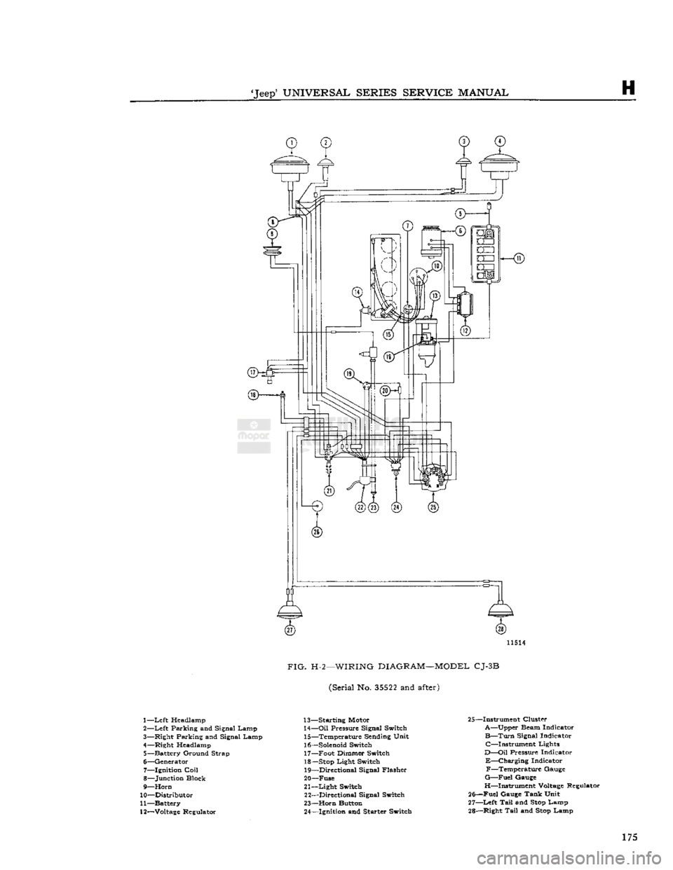
11514
FIG.
H-2—WIRING
DIAGRAM—MODEL
CJ-3B
(Serial No.
35522
and
after)
1—
Left
Headlamp
2—
Left
Parking and Signal Lamp
3— Right Parking and Signal Lamp
4— Right Headlamp 5— Battery Ground Strap
6— Generator 7— Ignition
Coil
8— Junction Block
9—
Horn
10— Distributor
11— Battery
12—
Voltage
Regulator 13— Starting Motor
14—
Oil
Pressure Signal Switch 15— Temperature Sending Unit
16—
Solenoid
Switch 17— Foot Dimmer Switch
18—
Stop
Light Switch 19— Directional Signal Flasher
20— Fuse
21—
Light
Switch 22— Directional Signal Switch
23—
Horn
Button 24— Ignition and Starter Switch 25—Instrument Cluster
A—Upper Beam Indicator
B—Turn
Signal Indicator C—Instrument Lights
D—Oil
Pressure Indicator
E—Charging
Indicator F—Temperature Gauge
G—Fuel
Gauge
H—Instrument
Voltage
Regulator
25—Fuel Gauge Tank Unit
27—
Left
Tail
and
Stop
Lamp
28— Right
Tail
and
Stop
Lamp 175
Page 177 of 376
'Jeep*
UNIVERSAL
SERIES
SERVICE
MANUAL
H
12968
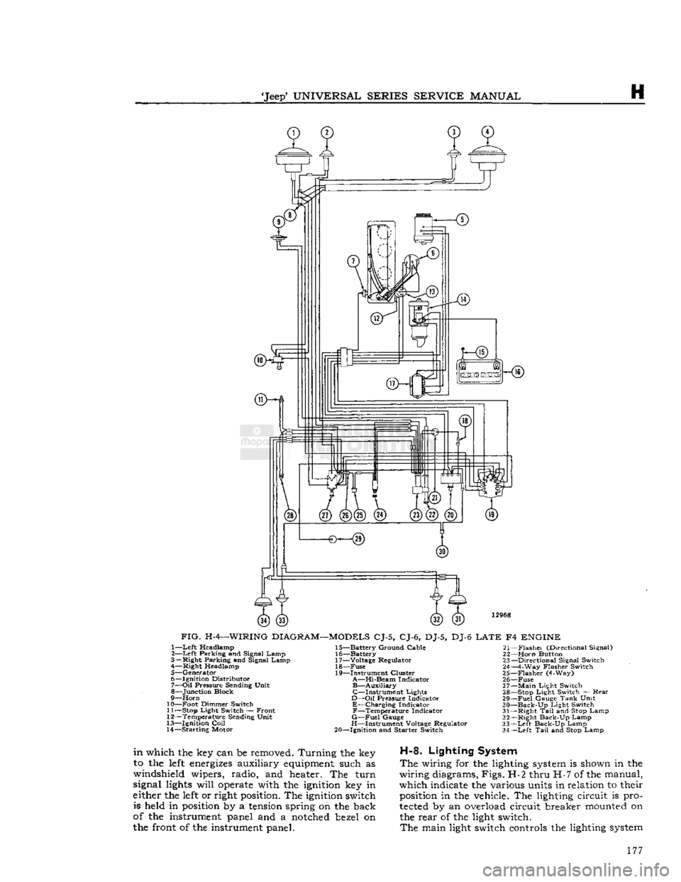
FIG.
H-4—WIRING
DIAGRAM—MODELS
CJ-5, CJ-6, DJ-5, DJ-6
LATE
F4
ENGINE
1—
Left
Headlamp
2—
Left
Parking and Signal Lamp
3— Right Parking and Signal Lamp 4— Right Headlamp
5— Generator
6— Ignition Distributor
7—
Oil
Pressure Sending Unit
8— Junction Block
9—
Horn
10— Foot Dimmer Switch 11—
Stop
Light Switch — Front
12— Temperature Sending Unit
13— Ignition
Coil
14— Starting Motor 15— Battery Ground Cable
16— Battery
17— Voltage Regulator 18—
Fuse
19— Instrument Cluster
A—Hi-Beam
Indicator
B—Auxiliary
C—Instrument
Lights
D—Oil
Pressure Indicator
E—Charging
Indicator
F—Temperature
Indicator
G—Fuel
Gauge
H—Instrument Voltage Regulator
20— Ignition and Starter Switch 21—
Flashei
(Directional Signal)
22—
Horn
Button 23— Directional Signal Switch
24— 4-Way Flasher Switch
25—
Flasher
(4-Way)
26—
Fuse
27—
Main
Light Switch 28—
Stop
Light Switch — Rear
29—
Fuel
Gauge
Tank
Unit
30—
Back-Up
Light Switch
31— Right
Tail
and
Stop
Lamp
32— Right Back-Up Lamp
33—
Left
Back-Up Lamp
34—
Left
Tail
and
Stop
Lamp
in
which the key can be removed. Turning the key
to the
left
energizes
auxiliary
equipment
such as
windshield wipers, radio, and heater. The turn
signal
lights
will
operate
with the
ignition
key in
either the
left
or right
position.
The
ignition
switch is held in
position
by a
tension
spring on the back
of the instrument panel and a
notched
bezel on
the front of the instrument panel.
H-8.
Lighting System
The
wiring for the lighting
system
is shown in the
wiring diagrams, Figs. H-2 thru H-7 of the manual,
which indicate the various units in relation to their
position
in the vehicle. The lighting circuit is pro
tected
by an overload circuit breaker
mounted
on the rear of the light switch.
The
main light switch controls the lighting
system
177
Page 178 of 376
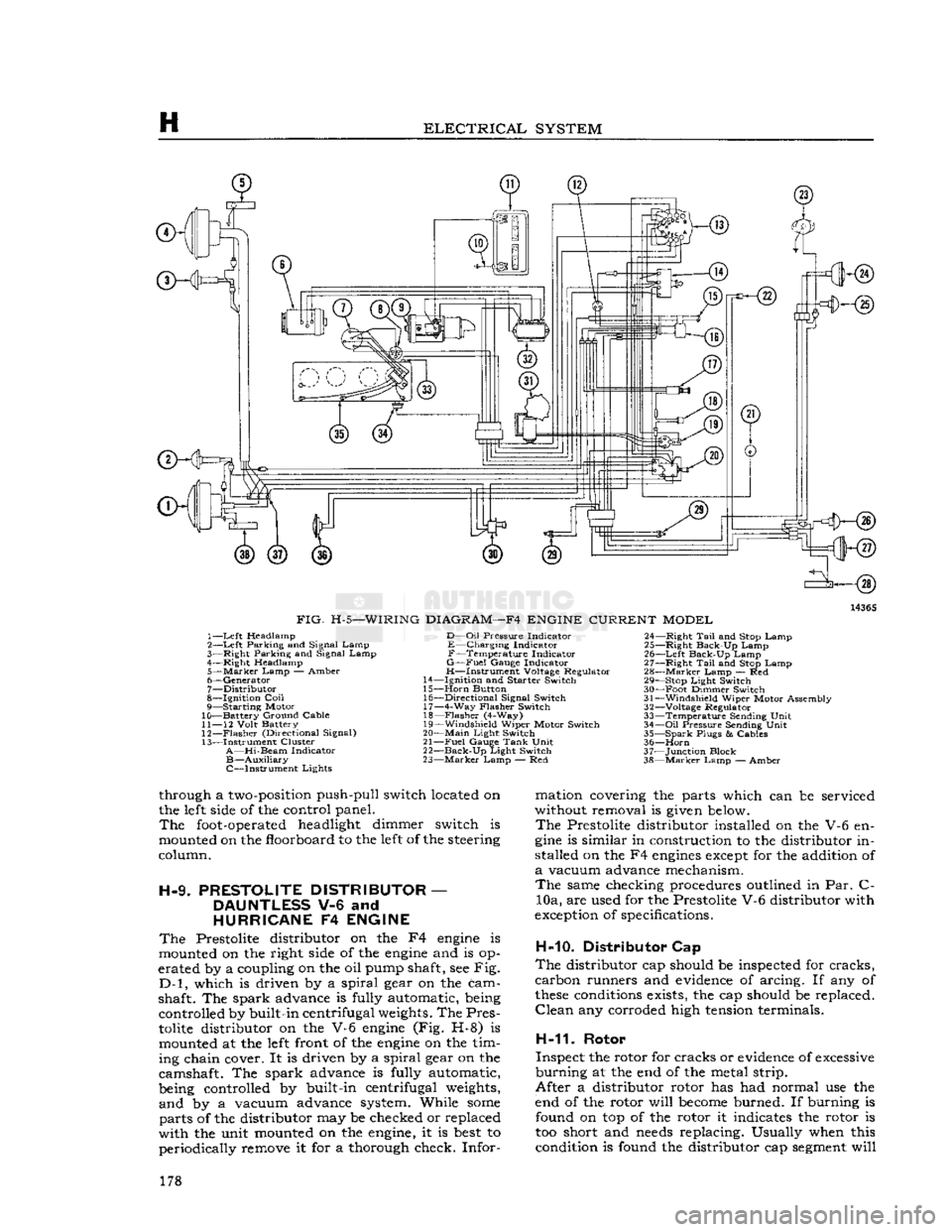
H
ELECTRICAL
SYSTEM
14365
FIG.
H-5—WIRING
DIAGRAM—F4
ENGINE
CURRENT
MODEL
1—
Left
Headlamp
2—
Left
Parking and Signal Lamp
3—
Right
Parking and Signal Lamp
4—
Right
Headlamp
5—
Marker
Lamp
— Amber
6—
Generator
7—
Distributor
8—
Ignition
Coil
9— Starting Motor
10— Battery Ground Cable
11—
12
Volt
Battery
12—
Flasher
(Directional Signal)
13— Instrument Cluster
A—Hi-Beam
Indicator
B—Auxiliary
C—Instrument Lights
D—Oil
Pressure
Indicator
E—Charging Indicator
F—Temperature Indicator
G—Fuel
Gauge
Indicator
H—Instrument Voltage Regulator
14—
Ignition
and
Starter
Switch
15—
Horn
Button 16—
Directional
Signal Switch 17— 4-Way
Flasher
Switch
18—
Flasher
(4-Way)
19—
Windshield
Wiper Motor Switch
20—
Main
Light
Switch
21—
Fuel
Gauge
Tank
Unit
22—
Back-Up
Light
Switch
23—
Marker
Lamp — Red 24—
Right
Tail
and Stop Lamp
25—
Right
Back-Up Lamp
26—
Left
Back-Up Lamp
27—
Right
Tail
and Stop Lamp
28—
Marker
Lamp — Red 29— Stop
Light
Switch
30— Foot Dimmer Switch
31—
Windshield
Wiper Motor Assembly
32—
Voltage Regulator
33— Temperature Sending
Unit
34—
Oil
Pressure
Sending
Unit
35— Spark
Plugs
&
Cables
36—
Horn
37— Junction Block
38—
Marker
Lamp — Amber
through a
two-position
push-pull switch located on
the
left
side
of the control panel.
The
foot-operated
headlight dimmer switch is
mounted on the floorboard to the
left
of the steering
column.
H-9.
PRESTOLITE
DISTRIBUTOR
—
DAUNTLESS
V-6 and
HURRICANE
F4
ENGINE
The
Prestolite distributor on the F4
engine
is
mounted on the right
side
of the
engine
and is op
erated by a coupling on the oil pump shaft, see Fig.
D-l,
which is driven by a spiral gear on the cam
shaft. The spark advance is fully automatic, being controlled by built-in centrifugal
weights.
The Pres
tolite
distributor on the V-6
engine
(Fig. H-8) is mounted at the
left
front of the
engine
on the tim
ing chain cover. It is driven by a spiral gear on the
camshaft. The spark advance is fully automatic,
being controlled by built-in centrifugal
weights,
and by a vacuum advance system. While
some
parts of the distributor may be checked or replaced
with the unit mounted on the
engine,
it is
best
to periodically remove it for a thorough check. Infor mation covering the parts which can be serviced
without removal is
given
below.
The
Prestolite distributor installed on the V-6 en
gine
is similar in construction to the distributor in
stalled on the F4
engines
except
for the addition of
a
vacuum advance mechanism.
The
same checking procedures outlined in Par. C- 10a, are used for the Prestolite V-6 distributor with
exception
of specifications.
H-10. Distributor Cap
The
distributor cap should be inspected for cracks,
carbon runners and
evidence
of arcing. If any of
these
conditions
exists, the cap should be replaced.
Clean
any corroded high
tension
terminals.
H-11.
Rotor
Inspect the rotor for cracks or
evidence
of
excessive
burning at the end of the metal strip.
After a distributor rotor has had normal use the
end of the rotor will
become
burned. If burning is found on top of the rotor it indicates the rotor is
too short and
needs
replacing. Usually when this condition is found the distributor cap
segment
will 178
Page 179 of 376
'Jeep'
UNIVERSAL
SERIES
SERVICE
MANUAL
H
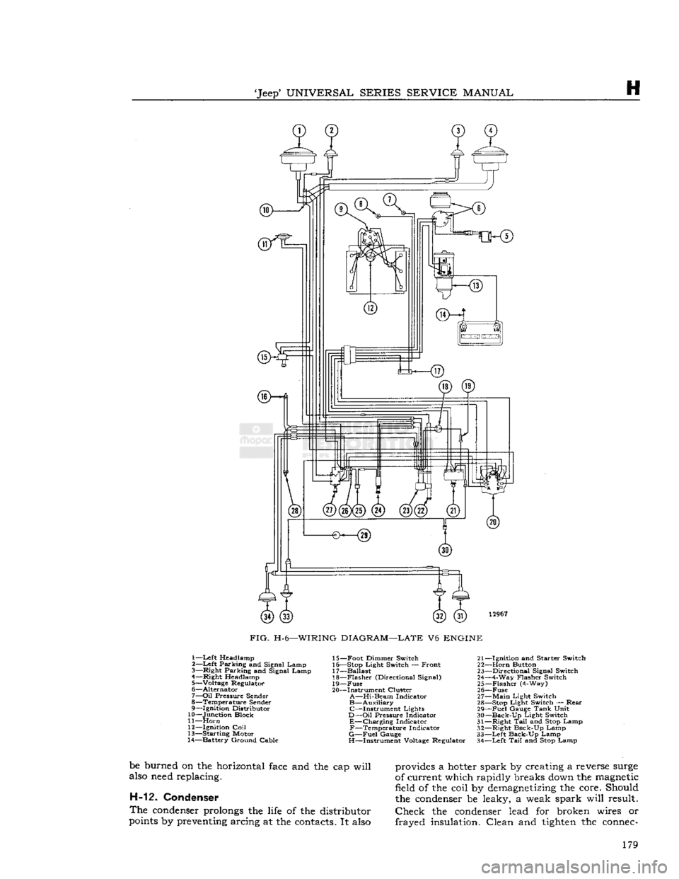
12967
FIG.
H-6—WIRING
DIAGRAM—LATE
V6
ENGINE
1—Left Headlamp
2—
Left
Parking and Signal Lamp
3—
Right
Parking and Signal Lamp
4—
Right
Headlamp
5— Voltage Regulator
6—
Alternator
7—
Oil
Pressure
Sender
8— Temperature
Sender
9—
Ignition
Distributor
10— Junction Block
11—
Horn
12—
Ignition
Coil
13— Starting Motor
14— Battery Ground Cable 15— Foot Dimmer Switch 21-
16— Stop
Light
Switch — Front 22-
17— Ballast 23-
18—
Flasher
(Directional Signal) 24-
19—
Fuse
25-
20— Instrument Cluster 26-
A—Hi-Beam
Indicator 27-
B—Auxiliary
28- C—Instrument Lights 29-
D—Oil
Pressure
Indicator 30-
E—Charging Indicator 31-F—Temperature Indicator 32-
G—Fuel
Gauge
33-
H—Instrument Voltage Regulator 34-
-Ignition
and
Starter
Switch
-Horn
Button
-Directional
Signal Switch
-4-Way
Flasher
Switch
-Flasher
(4-Way)
-Fuse
-Main
Light
Switch
-Stop
Light
Switch —
Rear
-Fuel
Gauge
Tank
Unit
-Back-Up
Light
Switch
-Right
Tail
and Stop Lamp
-Right
Back-Up Lamp
-Left
Back-Up Lamp
-Left
Tail
and Stop Lamp
be burned on the horizontal
face
and the cap will
also
need
replacing. H-12. Condenser
The
condenser
prolongs
the
life
of the distributor
points
by
preventing
arcing at the
contacts.
It
also
provides
a
hotter
spark by creating a reverse
surge
of current which rapidly breaks
down
the
magnetic
field of the coil by
demagnetizing
the core. Should
the
condenser
be leaky, a weak spark will result.
Check
the
condenser
lead for broken wires or
frayed insulation. Clean and
tighten
the
connec-
179
Page 188 of 376
H
ELECTRICAL
SYSTEM
colder plug may be desirable. However, under- or
over-heating is usually caused by factors other than the type of
spark
plugs and the cause should be determined before changing plugs. The design of the
engine
calls for plugs equivalent to Champion
J-8
for F4
engines
and
A.C.
44S or
UJ12Y
Champ
ion for the V6 engines, (as installed in production)
though any factor that consistently affects
engine
operating temperature may cause this requirement
to change. Overheating may be caused by in sufficient tightening of the plug in the head, which interferes with the flow of heat away from the firing
tip.
If this is the case, the plug gasket
will
show very
little flattening. Over-tightening, in
turn,
will
pro duce too easy a heat flow path and result in cold
plug operation.
This
will
be evident by excessive
flattening
and
deformation of the gasket.
Prevailing
temperatures, condition of the cooling system, and
air-fuel
mixture can affect the
engine
operating temperature and should be taken into consideration.
H-34.
GENERATOR
— F4
ENGINE
The
generator is an air-cooled, two-brush unit
which
cannot be adjusted to increase or decrease output. For replacement,
voltage
regulator and generator must be matched for
voltage
and capa
city,
polarity, and common source of manufacture.
Otherwise,
either a
loss
of ampere capacity or a
burned
out generator
will
result. Generators for
these
vehicles are 12-volt. Par. H-l explains the 12-volt system. Refer to the specifications at the
end of this section for information on correct generator rating for a specific model series.
The
circuit
breaker,
voltage
regulator, and current-
limiting
regulator are built into one combination
unit.
Because the regulator and battery are part
of the generator
circuit,
the output of the generator
depends upon the
state
of charge and temperature
of the battery.
With
a discharged battery, the
output
will
be high, decreasing proportionally as the battery
becomes
charged. For service informa
tion covering current regulator see Par. H-41.
H-36.
Generator
Maintenance
A
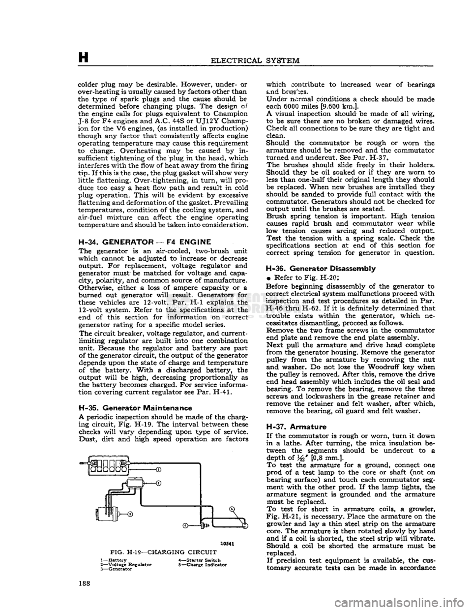
periodic inspection should be made of the charg
ing
circuit,
Fig. H-l9. The interval
between
these
checks
will
vary
depending upon type of service.
Dust,
dirt
and high speed operation are factors 10541
FIG.
H-19—CHARGING
CIRCUIT
1—
Battery
4-—Starter Switch
2—
Voltage
Regulator 5-—Charge Indicator
3—
Generator
which
contribute to increased wear of bearings
and
brushes.
Under
normal conditions a check should be made
each 6000 miles
[9.600
km.].
A
visual inspection should be made of all wiring,
to be sure there are no broken or damaged wires.
Check
all connections to be sure they are tight and
clean.
Should
the commutator be rough or worn the
armature
should be removed and the commutator
turned
and undercut. See Par. H-37.
The
brushes should slide freely in their holders.
Should
they be oil soaked or if they are worn to
less
than one-half their original length they should
be replaced. When new brushes are installed they should be sanded to provide
full
contact with the
commutator. Generators should not be checked for
output until the brushes are seated.
Brush
spring tension is important. High tension causes
rapid
brush and commutator wear while
low tension causes arcing and reduced output.
Test
the tension with a spring scale.
Check
the
specifications section at end of this section for
correct
spring tension for generator in question.
H-36.
Generator Disassembly
•
Refer to Fig. H-20:
Before beginning disassembly of the generator to
correct
electrical system malfunctions proceed with
inspection and
test
procedures as detailed in Par.
H-46
thru
H-62. If it is definitely determined that trouble exists within the generator, which necessitates dismantling, proceed as follows. Remove the two frame screws in the commutator
end plate and remove the end plate assembly. Next
pull
the armature and drive head complete
from
the generator housing. Remove the generator pulley from the armature by removing the nut
and
washer. Do not
lose
the Woodruff key when
the pulley is removed. After this, remove the drive
end head assembly which includes the oil seal and
bearing.
To remove the bearing, remove the three
screws and lockwashers in the grease retainer and remove the retainer and felt washer, after which,
remove the bearing, oil guard and felt washer.
H-37.
Armature
If
the commutator is rough or worn,
turn
it down
in
a lathe. After turning, the mica insulation be tween the
segments
should be undercut to a depth of 34* [0,8 mm.].
To
test
the armature for a ground, connect one
prod
of a
test
lamp to the core or shaft (not on
bearing
surface) and touch each commutator
seg
ment with the other prod. If the lamp lights, the
armature
segment
is grounded and the armature must be replaced.
To
test
for short in armature coils, a growler,
Fig.
H-21, is necessary. Place the armature on the growler and lay a thin steel strip on the armature
core.
The armature is then rotated slowly by hand
and
if a coil is shorted, the steel strip
will
vibrate.
Should
a coil be shorted the armature must be
replaced.
If
precision
test
equipment is available, the cus
tomary
accurate
tests
can be made in accordance 188
Page 195 of 376
'Jeep*
UNIVERSAL
SERIES SERVICE
MANUAL
H
no soldering or unsoldering of leads; two complete
rectifying
diode assemblies
which
eliminate the need
for removing and replacing individual diodes; a
corpplete isolation diode assembly; and a rotor
assembly complete with shaft,
pole
pieces, field
coil,
and slip rings.
The
transistorized
voltage
regulator is an electronic
switching device. It
senses
the
voltage
appearing
at the auxiliary terminal of the alternator and
supplies the necessary field current for maintaining
the system
voltage
at the output terminal. The
output current is determined by the battery electri
cal
load; such as headlights, heater, etc.
The
transistorized
voltage
regulator is a sealed
unit,
has no adjustments, and must be replaced
as a complete unit.
H-64. ALTERNATOR
PRECAUTIONS
The
following precautions must be observed to
prevent damage to the alternator and regulator.
a.
Never reverse battery connections. Always
check
the battery polarity with a voltmeter before
any
connections are made to be sure that all con
nections correspond to the battery ground polarity of the vehicle.
b.
Booster batteries for starting must be properly
connected. Make sure that the negative cable of
the booster battery is connected to the negative
terminal
of the battery in the vehicle. The positive
cable of the booster battery should be connected
to the positive terminal of the battery in the
vehicle.
c.
Disconnect the battery cables before using a fast charger.
d.
Never use a fast charger as a booster for
starting
the vehicle.
e.
Never disconnect the
voltage
regulator while
the
engine
is running.
f.
Do not ground the alternator output terminal.
g.
Do not operate the alternator on an open
circuit
with
the field energized.
h.
Do not attempt to polarize an alternator.
These
precautions are stated here as an aid to
service
personnel. They are also restated at appro
priate
places in the
text
of this section of the
manual.
H-65. ALTERNATOR
CHARGING
SYSTEM SERVICE
Important:
All alternator
tests
for the 35, 40 and
55 amp alternator are the same, however, there is a
difference
between
the location of the various ter
minals
and field current specifications. The field
current
of the 35 amp alternator should be 1.7 to 2.3 amps, 40 and 55 amp alternators should be 1.8
to 2.4 amps, with
full
battery
voltage
applied to
the filed coil. Disassembly and assembly procedures
are
the same for all three alternators.
Terminal
locations and wire harness color
codes
for the 35,
40 and 55 amp alternator are shown in Fig. H-38.
H-66.
Service Diagnosis
In
diagnosing a suspected malfunction of the
alternator
charging system, consideration must
be given to the complete electrical power plant of the vehicle; including the alternator, regulator,
ignition switch, charge indicator lamp, battery,
and
all associated wiring. If it is suspected that the
alternator
is not fully charging the battery and
fulfilling
the electrical requirements of the electrical
system, several checks should be made before
checking
the alternator itself:
Note:
Whenever service is required in connection
with
an alternator problem, the first
step
should be to verify that the wiring harness hook-up is correct
as indicated in Fig. H-38.
a.
Test the condition of the battery and
state
of
charge
(Par. H-2).
If the battery is not fully charged
and
in
good
condition, use a replacement battery
for making alternator system
tests.
Caution:
Make certain that the negative battery
post
is connected to ground when making the
battery installation. Serious damage to the alter
nator
can result if battery polarity is reversed.
b.
Check
fan belt for proper tension (Par.
C-27).
Caution:
To increase belt tension, apply pressure
to alternator front housing only as permanent damage can result if pressure is applied to
rear
housing.
H-67.
Alternator In Vehicle Tests
The
following
tests
are made with the alternator
in
the vehicle with output and regulator connec
tions maintained to the alternator except as noted
in
Fig. H-27 and H-28. The field plug and
voltage
regulator are disconnected for
these
tests.
The
tests
are given in proper order and detail in the
following paragraphs.
a.
Isolation Diode Test: To determine if the isola
tion diode is open or shorted, refer to Par. H-69.
b.
Alternator Output Test: To isolate the trouble
to the alternator or regulator, refer to Par. H-70.
c.
Alternator
Field
Circuit
Test: To determine the condition of the field
circuit
(brushes and rotor),
refer
to Par. H-73.
d.
Brush
Insulation
and Continuity
Test:
To deter
mine the condition of the
brush,
refer to
Par.
H-75.
e.
Rotor In-Vehicle Test: To determine whether
the rotor coil is open or shorted, refer to
Par.
H-73.
f. Any further
tests
must be conducted with the
alternator
removed and disassembled. When this
is done, the condition of the rotor, the rectifying
and
isolation diodes, and the stator can be further
tested.
A
commercial alternator tester Sun
Electric
Model
VAT-20
or equivalent can be used to make all
necessary
tests
on the alternator system. If a com
mercial
tester is used, follow the recommended
testing procedure outlined by the tester manu
facturer.
If
a commercial tester is not available, follow the
testing procedure as outlined in this manual.
H-68.
Test Equipment
a.
Volt Ampere Tester such as Sun
Electric
Model
VAT-20
or equivalent with meter ranges as shown
in
the following list can be used. 195
Page 197 of 376
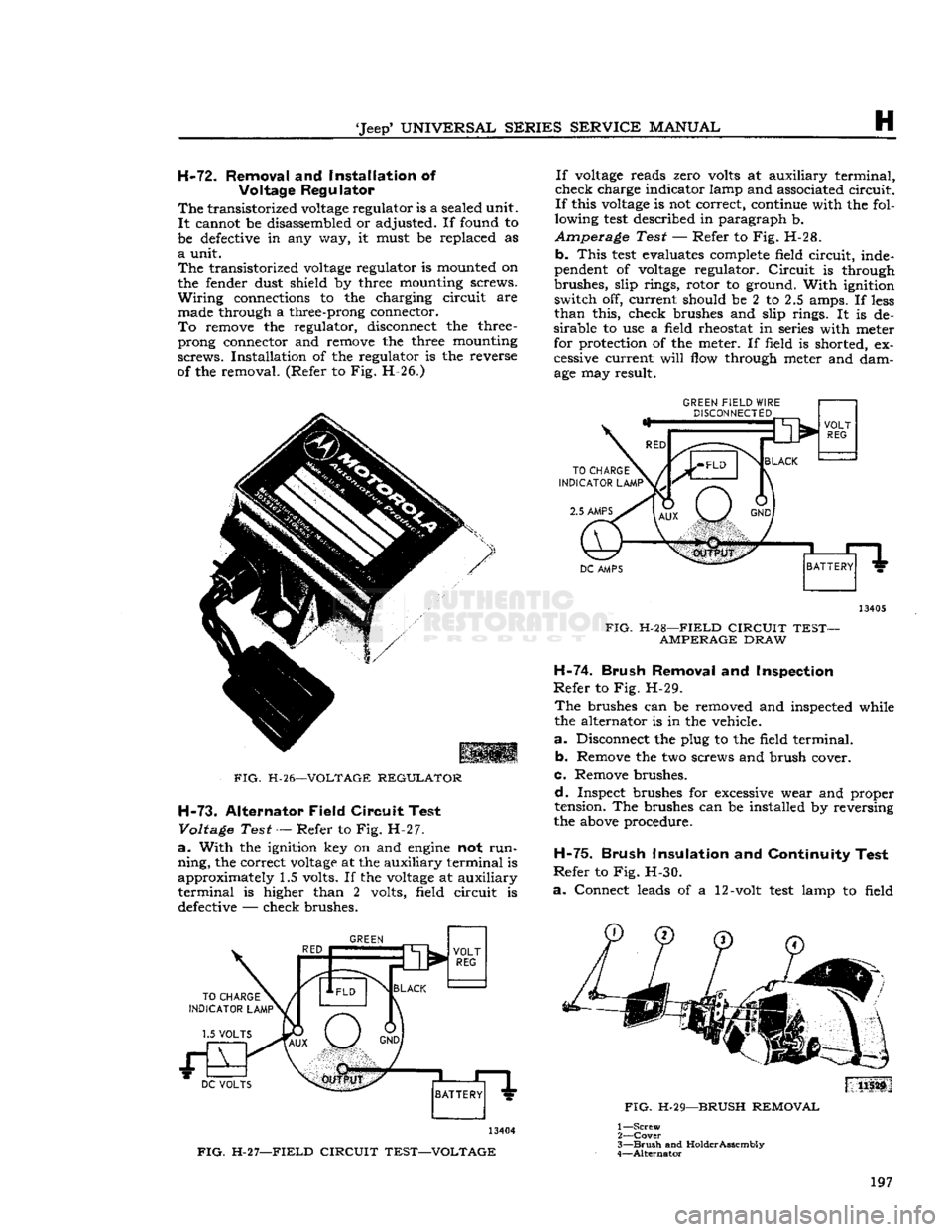
'Jeep'
UNIVERSAL SERIES SERVICE
MANUAL
H
H-72.
Removal
and
Installation
of
Voltage Regulator
The
transistorized
voltage
regulator is a sealed unit.
It
cannot be disassembled or adjusted. If found to
be defective in any way, it must be replaced as
a
unit.
The
transistorized
voltage
regulator is mounted on
the fender dust shield by three mounting screws.
Wiring
connections to the charging circuit are made through a three-prong connector.
To
remove the regulator, disconnect the three
-
prong connector and remove the three mounting
screws.
Installation of the regulator is the reverse
of the removal. (Refer to Fig. H-26.)
FIG.
H-26—VOLTAGE
REGULATOR
H-73.
Alternator Field Circuit Test
Voltage
Test — Refer to Fig. H-27.
a.
With the ignition key on and
engine
not
run
ning,
the correct
voltage
at the auxiliary terminal is
approximately 1.5 volts. If the
voltage
at auxiliary
terminal
is higher than 2 volts, field circuit is defective — check brushes.
GREEN
13404
FIG.
H-27—FIELD
CIRCUIT TEST—VOLTAGE If
voltage
reads zero volts at auxiliary terminal,
check charge indicator lamp and associated circuit.
If
this
voltage
is not correct, continue with the fol
lowing
test
described in paragraph b.
Amperage Test — Refer to Fig. H-28. b.
This
test
evaluates complete field circuit, inde
pendent of
voltage
regulator.
Circuit
is through
brushes, slip rings, rotor to ground. With ignition switch off, current should be 2 to 2.5 amps. If
less
than
this, check brushes and slip rings. It is de
sirable
to use a field rheostat in series with meter
for protection of the meter. If field is shorted, ex
cessive current
will
flow through meter and dam
age may result.
GREEN
FIELD
WIRE
DISCONNECTED
13405
FIG.
H-28—FIELD
CIRCUIT TEST- AMPERAGE
DRAW
H-74.
Brush Removal
and
Inspection
Refer
to Fig. H-29.
The
brushes can be removed and inspected while
the alternator is in the vehicle.
a.
Disconnect the plug to the field terminal. b. Remove the two screws and brush cover.
c. Remove brushes.
d.
Inspect brushes for excessive wear and proper
tension. The brushes can be installed by reversing
the above procedure.
H-75.
Brush Insulation
and
Continuity Test
Refer
to Fig. H-30.
a.
Connect leads of a 12-volt
test
lamp to field
FIG.
H-29—BRUSH
REMOVAL
1—
Screw
2—
Cover
3—
Brush
and
Holder
Assembly
4—
Alternator
197
Page 202 of 376
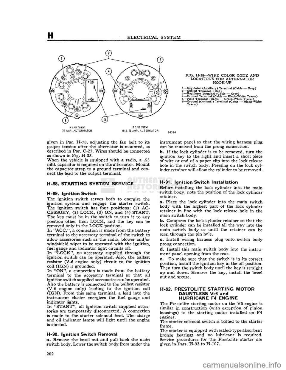
H
ELECTRICAL
SYSTEM
FIG.
H-38—WIRE
COLOR CODE
AND
LOCATIONS
FOR
ALTERNATOR HOOK-UP
1— Regulator (Auxiliary)
Terminal
(Cable —
Grey)
2— Output
Terminal:
(Red)
3—
Regulator
Terminal
(Cable —
Grey)
4—
Ground
Terminal
(Cable — Black-White
Tracer)
5—
Field
Terminal
(Cable — Green-White
Tracer)
6—
Ground
(Optional)
Terminal
(Cable — Black-White
Tracer)
REAR
VIEW
35
AMP.
ALTERNATOR
REAR
VIEW
40
& 55 AMP.
ALTERNATOR
given in Par. H-78, adjusting the fan belt to its
proper tension after the alternator is mounted, as described in Par. C-27. Wires should be connected
as shown in Fig. H-38.
When
the vehicle is equipped with a radio, a .55
mfd. capacitor is required on the alternator. Mount
the capacitor strap to a ground terminal and con
nect the lead to the output terminal.
H-88.
STARTING
SYSTEM
SERVICE
H-89.
Ignition
Switch
The
ignition switch serves both to energize the
ignition system and
engage
the starter switch.
The
ignition switch has four positions: (1) AC
CESSORY,
(2)
LOCK,
(3) ON, and (4)
START. The
key must be in the switch to turn it to any position other than
LOCK,
and the key can be
removed only in the
LOCK
position.
In "ACC",
a connection is made from the battery
terminal
to the accessory terminal of the switch to
allow accessories such as the radio, blower and/or
windshield wiper to be operated with the ignition, fuel
gauge
and indicator light circuits off.
In "LOCK",
no accessory supplied through the
ignition switch can be operated. Also, the ballast
resistor (V-6
engine
only) circuit to the ignition
coil
(IGN) is grounded.
In
"ON", a connection is made from the battery
terminal
to the accessory terminal so that all
ignition switch supplied accessories can be operated. Also the battery is connected to the ballast resistor
(V-6
engine
only) leading to the ignition coil
(IGN).
From
this same terminal, a lead
into
the
instrument cluster energizes the fuel
gauge
and
indicator lights.
In "START",
all ignition switch supplied acces
sories are temporarily disconnected. A connection is made to the starter solenoid lead. The charge
and
oil indicator lamps
will
light until the
engine
is started.
H-90.
Ignition
Switch
Removal
a.
Remove the bezel nut and pull back the main
switch body.
Lower
the switch
body
from under the instrument panel so that the wiring harness plug
can
be removed from the prong connection,
b. If the lock cylinder is to be removed, turn the
ignition key to the right and insert a short
piece
of wire or end of a paper clip
into
the lock release
hole
in the switch body. Pressing on the lock
cyl
inder retainer
will
allow the cylinder to be removed.
H-91.
Ignition
Switch
Installation
Before installing the lock cylinder
into
the main
switch body,
note
the position of the lock cylinder
retainer.
a.
Place the lock cylinder
into
the main switch
body
with the highest part of the lock cylinder
retainer in line with the lock release
hole
in the
main
switch body.
b. Compress the lock cylinder retainer so that the
lock cylinder can be installed all the way
into
the
main
switch
body
or until the retainer can be
seen
through the pin hole.
c.
Install
wiring harness plug
onto
switch
body
prong connection.
d.
Install
this main switch
body
into
the instru
ment panel opening from the
rear.
e. To make sure that the switch is in its correct position, install the ignition key in the off position.
Then
turn the switch
body
until the key is straight
up and down. Remove the key, install the bezel
nut and secure.
H-92.
PRESTOLITE
STARTING
MOTOR
DAUNTLESS
V-6 and
HURRICANE
F4
ENGINE
The
Prestolite starting motor on the V6
engine
is
similar
in construction (with exception of pinion housings) to the starting motor installed on F4
engines.
The
starter solenoid switch is bolted to the starter
frame.
The
starter is equipped with
sealed-type
absorbent
bronze bearings and no lubricant is required. Service procedures for the Prestolite starter are
given in
Pars.
H-93 to H-107. 202