service indicator JEEP CJ 1953 Owner's Manual
[x] Cancel search | Manufacturer: JEEP, Model Year: 1953, Model line: CJ, Model: JEEP CJ 1953Pages: 376, PDF Size: 19.96 MB
Page 211 of 376
'Jeep'
UNIVERSAL
SERIES SERVICE
MANUAL
H
Note:
Pinion clearance cannot be adjusted. If
clearance is not correct, motor must be disassem
bled and checked for the above mentioned defects.
Any
defective parts must be replaced.
H-118. Starting Motor Test —
Genera!
To
obtain
full
performance data on a starting motor, or to determine the cause of abnormal
operation, the motor should be submitted to no-
load and locked armature
tests,
with equipment designed for such
tests.
A high-current variable resistance is required to obtain the specified volt
age at the starting motor.
This
is necessary since
a
small variation in the
voltage
will
produce a
marked
difference in the current
drawn.
H-119.
Starting Motor No-Load Test
This
test
requires a DC voltmeter capable of
read
ing
voltages
in a 12-volt
circuit,
a DC ammeter
with
maximum range of several hundred amperes,
a
high-current variable resistance, an rpm. in
dicator,
and a fully-charged, 12-volt battery.
a.
Connect a jumper lead
between
S terminal
and
large battery terminal of starter solenoid.
Con
nect voltmeter
between
either of
these
terminals (positive) and motor frame (negative, ground).
Connect
ammeter and variable resistance in series
between
positive terminal of battery and battery
terminal
of solenoid. Set up rpm. indicator to show starting motor speed.
b.
Initially,
adjust variable resistance to a value of
approximately .25 ohm. To complete the
circuit,
connect negative terminal of battery to motor
frame.
Adjust variable resistance to obtain a volt meter reading of 10.6 volts;
note
speed of starting motor and ammeter reading. Motor speed should
be
6750
to
10,500
rpm.; ammeter reading should
be 50 to 80 amperes.
c. Rated speed and current indicate normal condi
tion of the starting motor. Low speed and high
cur
rent
may show friction; this could be caused by
tight, dirty, or worn bearings, bent armature shaft,
or
a
loose
field
pole
shoe
dragging against the
armature.
It could also be caused by a short-cir cuited armature, or by grounded armature or field
coils.
d.
Failure
to operate and high current indicates
a
direct short circuit to ground at either the battery
terminal
or field coils.
e.
Failure
to operate and no current are usually
caused by broken brush springs, worn brushes, high insulation
between
commutator
bars,
or
some
other
condition preventing
good
contact
between
the brushes and commutator. It can also be caused by
open circuit in either the field coils or armature coils.
f. Low speed and low current show high resistance due to poor connections, defective leads, dirty com
mutator, or one of the conditions mentioned in e,
above.
g. High speed and high current indicates a short
circuit
in the field coils. H-120-
Locked
Armature Test
This
test
requires a DC voltmeter with range ap
propriate
to read
voltages
in a 12-volt
circuit,
a DC
ammeter with maximum range of several hundred
amperes, a high-current variable resistance, a
clamping fixture to lock
together
the motor shaft
and
case, and a fully-charged 12-volt battery.
a.
Connect a jumper lead
between
S terminal and
large battery terminal of starter solenoid. Connect
voltmeter
between
either of
these
terminals (posi
tive) and motor frame (negative, ground). Connect
ammeter and variable resistance in series
between
positive terminal of battery and battery terminal
of solenoid.
Install
clamping fixture to lock motor
shaft and case
together
securely.
b.
Initially,
adjust variable resistance to approxi
mately .05 ohm. To complete the
circuit,
connect
negative terminal of battery to motor frame. Ad
just
variable resistance to obtain a voltmeter
read
ing of 4.0 volts. Ammeter reading should be 280
to 320 amperes.
H-121.
Solenoid Starter Switch — Delco
The
solenoid-type switch is mounted directly on
the starting motor.
This
type of switch is energized
by turning the ignition key to the extreme right position. Should the solenoid switch
fail
in service
it
is necessary to install a new assembly.
Should
a starting motor
fail
to deliver maximum power the fault may be due to
voltage
drop at the
starter
switch contacts due to corrosion or burning.
Check
the switch by comparing the
voltage
at the
battery across the terminals. The
voltage
drop
should not exceed .05 volts per 100 amperes.
In
order to remove the starter solenoid, it is neces
sary
to remove the starter assembly.
H-122.
ELECTRICAL
INSTRUMENTS
H-123.
Fuel
Gauge —
CJ-3B
The
fuel
gauge
circuit is composed of the indicating
unit,
mounted on the instrument panel, and the
fuel tank unit, connected by a single wire through the ignition switch.
Should
the
gauge
fail
to register, check all wire con nections to be sure they are tight and clean; also
be sure both units are well grounded. If, after this
check, the
gauge
does
not indicate properly, remove
the wire from the tank unit and connect it to a
new tank unit which must be grounded to the tank
or
frame for
test.
Turn
the ignition switch "ON"
and
move
the float arm through its range of travel,
watching the dash unit to determine if it indicates
correctly.
If it fails to do so the trouble is probably
in
the dash unit and it should be replaced.
Should
a new tank unit be unavailable for this
test,
disconnect tank unit wire at the instrument panel
gauge.
Connect one lead of a 12 V, 1 CP
test
light
to the instrument panel unit terminal and with the
ignition switch
"ON"
ground the other lead. If the
unit is operating correctly the pointer
will
move
approximately three-quarter across the
dial.
Do not attempt to repair either unit; replacement
is the only precedure. 211
Page 213 of 376
'Jeep'
UNIVERSAL
SERIES SERVICE
MANUAL
H
FIG.
H-52—MAIN
LIGHT SWITCH (LATE)
1—
Circuit
Breaker
2—
Light
Switch
3—
Rear
Lights
4—
Head
Lights
5—
Parking
Lights
The
light switch shown in
Fig.
H-51 was superseded
by the one shown in
Fig.
H-52.
H-127.
Headlight Dimmer Switch To
remove the headlight dimmer switch, first raise
the hood and disconnect the wires attached to the
switch.
Then
remove the two screws that hold the
dimmer
switch to the floor board. Remove the
switch.
Check
the operation of the dimmer switch
with
a
test
light. A
circuit
across two different pairs of contacts (one to headlights, the other to the
high-beam indicator light) should alternately light
the
test
lamp when the switch is operated.
H-128.
Stop Light Switch
The
stop
light switch is of the diaphragm type.
Should
the switch
become
inoperative, it is neces
sary
to install a new one.
Current
production vehicles are equipped with two
stop
light switches
that operate independently of each other. Both
switches are located along the
left
side of frame, in the front and
rear
brake lines.
Caution:
Do not apply the brakes while making
this exchange as air may enter the hydraulic line.
Bleed
the brakes after replacing the switch.
Fig.
H-54 shows the wiring of the
stop
light
circuit.
11500
FIG.
H-53—STOP
LIGHT SWITCH
FIG.
H-54—STOP
LIGHT CIRCUIT
1— Stop
Light
Switch
2—
Light
Switch
3—
Tail
Light
H-129. Head Lamp Service
H-130.
Head Lamp Replacement
Refer
to Fig. H-59.
Each
sealed beam head lamp can only be replaced as a
complete
unit.
A
sealed beam unit may be replaced by the fol lowing procedure:
a.
Remove door screw.
b.
Remove door.
c.
Remove retaining screws and retaining
ring.
d.
Remove sealed beam unit.
Installation
of sealed beam unit is the reverse of
above procedure. When replacing head lamps,
check
lamp aim following procedures described in
Par.
H-132.
FIG.
H-55—PARKING
LIGHT (EARLY)
1—
Bezel
2—
Lens
3—
Bulb
4—
Gasket
5—
Housing
and Cable
6—
Screw
213
Page 217 of 376
'Jeep'
UNIVERSAL
SERIES
SERVICE
MANUAL
H
cuit
lights,
the
signal switch
is
inoperative
and
must
be
replaced.
H-139.
Hazard
Warning Lights
All
current production vehicles
are
equipped with
a
four-way flasher warning system.
The
control switch
is
located
on the
instrument panel left
of
the steering column.
With
the
switch pulled
out,
the
two
front and
two
rear
turn
signal lights flash
on and
off
simultaneously,
as do
both
turn
signal
indicator
lights
on the
instrument clusters.
H-140.
Marker
Lights and Reflector Assembly
The
marker
lights
and
reflector assemblies
on
current
production vehicles
are
mounted
on the
side
of
the front fender and
on the
side
of
the
rear
quarter
panel.
The
spare wheel also mounts
a
marker
light. Some earlier production vehicles have
reflex reflectors mounted on the side of the hood and
on
the
side
of
the
rear
quarter panel. determine
if
dash wiper switch or wiring
is at
fault,
disconnect wiring harness from wiper motor
and
try
operating wiper independently
of
dash switch.
If
still
inoperative
see
procedure under
Par.
H-145.
b. Wiper
will
not
shut
off
— Determine
if
wiper
has both
low
and high speeds, slow speed only,
or
high speed only.
It is
important that
the
wiper
operates
at low
speed during parking cycle.
Dis
connect wiring harness from wiper motor
and try
operating wiper independently
of
dash switch.
If
wiper
shuts
off
correctly with
crank
arm
in
park
position and wiper has both speeds, check
the
lead
between
terminal
and
dash switch ground
and
check
for
defective dash switch.
If
wiper shuts
off
correctly,
but has
high speed only, check lead
be
tween wiper terminal and dash switch
for an
open
circuit
and check
for
defective dash switch.
If
still
inoperative,
see
Par. H-145.
c. Wiper
has
only fast speed.
Check
for
defective dash switch
or
open lead
between
terminal
and
dash switch.
H-141.
Windshield Wiper System
Early
production vehicles equipped with
the
Dauntless V-6
engine
have
two
single speed wind
shield wiper motors mounted above
the
windshield inside
the
vehicle. The wiper motors
are
operated
and
controlled
by a
switch located
on the
instru
ment panel.
Current
production vehicles with stationary wind
shield have
a
two-speed
electric windshield wiper motor mounted below
the
windshield outside
the
vehicle on the driver's side. The wiper motor switch is located
on the
instrument panel
to the
left
of
the steering column.
H-142.
Two-Speed Wiper Motor
The
two-speed
electric wiper motor
is
operated and
controlled
by a
turn
type, three poled, dash switch,
containing
a 6
amp. circuit breaker.
Current
flow
is directed from
the
battery through
the
ignition
switch
to the
wiper dash switch assembly
to the
two-speed
wiper motor, which passes current from the designated motor brush (high,
low or
park)
to
the armature circuit
to
ground.
H-143.
Troubleshooting Procedure
Troubleshooting procedures
are
divided into
two
categories: wiper troubleshooting
in
vehicle; wiper
troubleshooting
on
bench.
Fig. H-65 and H-66
illustrates connecting leads
of the
two-speed
wiper for either bench operation
or to run
wiper inde
pendently
of
dash switch and vehicle wiring when
installed
in the
vehicle.
H-144. Wiper Troubleshooting
in
Vehicle
Typical
wiper troubles and remedies are
as
follows
:
a.
Wiper
is
inoperative
—
Check
wiper switch
cir
cuit
breaker; wiring harness connection
at
wiper
motor
and
wiper switch; wiper motor
feed
wire
from
ignition starter switch
to
wiper switch;
and
check wiper
on
switch
to be
securely mounted.
With
ignition switch
on,
check
for 12
volts
at
har
ness
terminal that connects
to
wiper terminal.
To
BLACK
PARK
GREEN *-
RED m~
LOW
PARKING
<^^>
SWITCH
V^-O*'
HIGH
FIG.
H-64—WIRING
DIAGRAM
FIG.
H-65—WINDSHIELD
WIPER
SWITCH
ASSEMBLY
(EARLY)
1.
Park
(black)
2. Low (green)
3.
High (red)
d.
Wiper
has
only slow speed
and
shuts
off
with
dash switch in high speed position. Reverse harness
leads that connect
to
wiper terminals.
e. If
blades
do not
return
to
park
position when
wiper
is
turned
off,
check wiper ground connection
to vehicle body. Remove wiper from vehicle
and
check
for
dirty, bent,
or
broken
park
switch con
tacts.
f.
If
wiper speed
is
normal
in
slow,
but too ex
cessive
in
fast speed, check for an open terminal. 217
Page 296 of 376
N
REAR
AXLE
f. Inspect axle shaft thrust block for
excessive
wear
or visible damage. The wear surface on the op
posite
ends
of the blocks, must be smooth.
Note:
Thrust
block used with semi-float tapered
axles only.
g. Inspect differential pinion shaft lock pin for
damage or
looseness
in case. Replace pin or case as necessary.
h.
Inspect drive gear and pinion for worn or
chipped
teeth
or damaged attaching
bolt
threads.
If
replacement is necessary, replace both the drive
gear and drive pinion as
they
are available in
matched
sets
only.
i.
Inspect drive pinion bearing
cones,
cups and
rollers
for pitting, galling,
excessive
wear, or other
visible damage. If inspection reveals that either are
unfit for further service, replace both cup and
cone,
j.
Inspect differential
carrier
for cracks or other
visible damage which would render it unfit for
further
service. Raised metal on the shoulder of
bearing cup bores
incurred
in removing pinion cups should be flattened by use of a flat
nose
punch.
k.
Inspect drive pinion for damaged bearings
journals
and mounting shim surface or excessively
worn
splines. If replacement is necessary, replace both the drive pinion and drive gear as
they
are
available in matched
sets
only.
I.
Inspect companion
flange
for
cracks,
worn
splines, pitted, rough or corroded oil seal contacting
surface.
Repair
or replace companion
flange
as
necessary.
m.
Inspect drive pinion bearing shim pack for
broken,
damaged or distorted shims. Replace if
necessary during establishment of pinion bearing
preload.
N-16.
Pinion
Installation
and Adjustment
Refer
to
Fig.
N-3 and N-7.
Adjustment
of the pinion is accomplished by the use of shims placed
between
the inner bearing cup
and
the axle housing and
between
the pinion shoulder and the outer bearing. The shims behind
FIG.
N-2
5—INSTALLING
OUTER BEARING
CUP
FIG.
N-26—PINION
BEARING INSTALLING
SLEEVE
1—Sleeve
the inner bearing cup adjust the position of pinion
in
relation to the ring gear. The shims behind the outer bearing adjust the pinion inner and outer
bearing preload.
Install
the pinion as follows:
a.
Install
outer bearing cup using Tool W-264 on model 27 and W-126 on model 44 axles, as shown
in
Fig. N-25.
b.
Install
the inner bearing cup using Tool W-126
on model 27 axles, and Tool W-344 on model 44
axles to drive the cup
into
the housing.
c. Use Tool C-3095 to press the inner bearing
cone
and
roller
onto
the pinion shaft on axle Model 44.
Other
models
use Tool W-262 as shown in Fig.
N-26.
d.
Place the pinion in the housing and install a .065"
[1,651
mm.] shim, the inner
cone
and roller*
sleeve
SP-1997 from Tool W-162, and the pinion
nut.
e. Select the proper pinion adjusting
gauge
to obtain the correct reading for the differential model.
The
pinion adjusting fixture must first be set by the use of a master
gauge
which is included in the
W-99
Kit. Gauge block W-101-A-24 or SP5433 is stamped with the letter H which indicates it is used
to set the adjusting fixture on Model
27AF
axle differentials. Gauge block W-101-A-22 or SP5453 is stamped with the letters D, G, F, A, C, E and B.
Use the letter E for Model 44 axle differentials.
Tool
SP-5264 is used with the
dial
indicator in
W-99
Tool Set for
setting
pinion.
After
selecting the proper
gauge,
the adjusting fix
ture can be set as follows: 296
Page 297 of 376
'Jeep'
UNIVERSAL
SERIES SERVICE
MANUAL
N
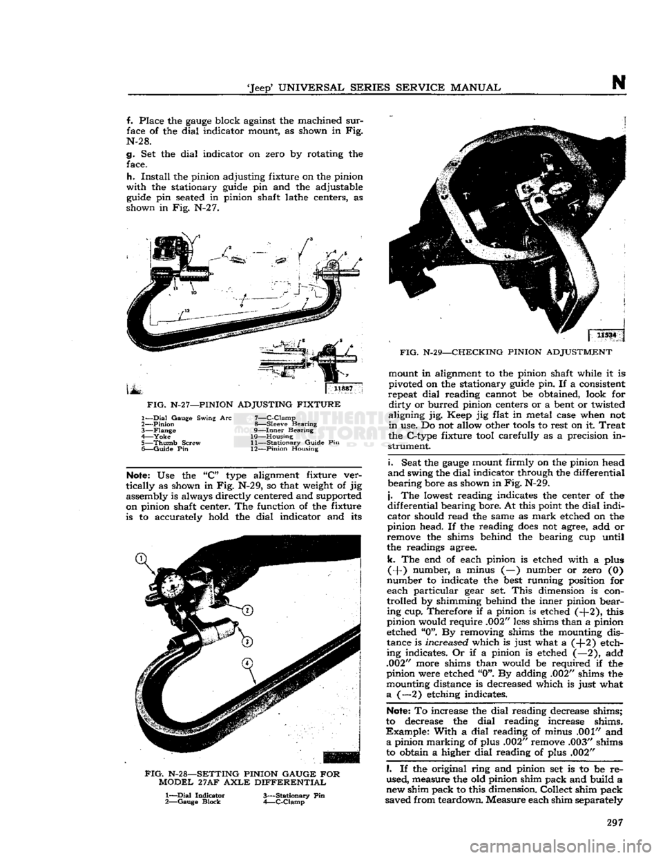
f. Place the
gauge
block against the machined
sur
face of the dial indicator mount, as shown in Fig.
N-2 8.
g. Set the dial indicator on zero by rotating the face.
h.
Install
the pinion adjusting fixture on the pinion
with
the stationary
guide
pin and the adjustable
guide
pin
seated
in pinion shaft lathe centers, as
shown in Fig. N-2 7.
FIG.
N-2
7—PINION
ADJUSTING FIXTURE
7—
C-Clamp
8— Sleeve Bearing
9—
Inner
Bearing
10— Housing 11—
Stationary
Guide Pin
1—
Dial
Gauge Swing Arc
2—
Pinion
3—
Flange
4—
Yoke
5—
Thumb
Screw
6—
Guide
Pin 12—Pinion Housing
Note:
Use the "C"
type
alignment fixture ver
tically
as shown in Fig. N-29, so that
weight
of jig assembly is always directly centered and supported
on pinion shaft center. The function of the fixture is to accurately hold the dial indicator and its
FIG.
N-28—SETTING
PINION
GAUGE FOR
MODEL
27AF
AXLE
DIFFERENTIAL
1—
Dial
Indicator
2—
Gauge
Block
3—
Stationary
Pin
4—
C-Clamp
j
11534 j
FIG.
N-29—CHECKING
PINION
ADJUSTMENT mount in alignment to the pinion shaft while it is
pivoted on the stationary
guide
pin. If a consistent
repeat dial reading cannot be obtained, look for
dirty
or burred pinion centers or a
bent
or twisted
aligning jig. Keep jig flat in metal case when not
in
use. Do not allow other
tools
to rest on it
Treat
the C-type fixture
tool
carefully as a precision in
strument.
i.
Seat the
gauge
mount firmly on the pinion head
and
swing the dial indicator through the differential
bearing bore as shown in
Fig.
N-29.
j.
The
lowest
reading indicates the center of the
differential bearing bore. At this point the dial indi
cator should read the same as
mark
etched on the
pinion head. If the reading
does
not agree, add or
remove the shims behind the bearing cup until
the readings agree.
k.
The end of each pinion is etched with a plus
(+) number, a minus (—) number or zero (0)
number to indicate the
best
running position for
each particular gear set.
This
dimension is con
trolled by shimming behind the inner pinion bear ing cup. Therefore if a pinion is etched (-f-2), this
pinion would require .002"
less
shims than a pinion
etched "0". By removing shims the mounting dis
tance is increased which is just what a (+2) etch
ing indicates. Or if a pinion is etched (—2), add
.002" more shims than would be required if the
pinion were etched "0". By adding .002" shims the mounting distance is decreased which is just what
a
(—2) etching indicates.
Note:
To increase the dial reading decrease shims;
to decrease the dial reading increase shims.
Example:
With a dial reading of minus .001" and
a
pinion marking of plus .002" remove .003" shims
to obtain a higher dial reading of plus .002"
I.
If the original ring and pinion set is to be re
used, measure the old pinion shim pack and build a
new shim pack to this dimension. Collect shim pack
saved from teardown. Measure each shim separately 297
Page 299 of 376
'Jeep9
UNIVERSAL
SERIES SERVICE
MANUAL
N
c.
Check
side gear clearance as described in Par.
N-18.
d.
Examine contacting surfaces of ring gear and
differential case for
burrs
or foreign matter.
e.
Assemble ring gear on differential case with assembly
hole
on each lined up.
f.
Tap ring gear
into
place with mallet.
g.
Install
ring gear screws. Torque 35 to 55 lb-ft. [4,84 a 7,60 kg-m.].
N-18.
Adjustment
of
Differential
Side
Gears
Clearance
between
the differential side gears and differential case should be .000" to .006"
[0,000
a
0,192 mm.] Procedure for checking clearance is as
follows:
a.
With
the differential positioned as shown in
Fig.
N-31, tap the differential lightly on a flat
sur
face so the differential gears
settle
into
proper
position.
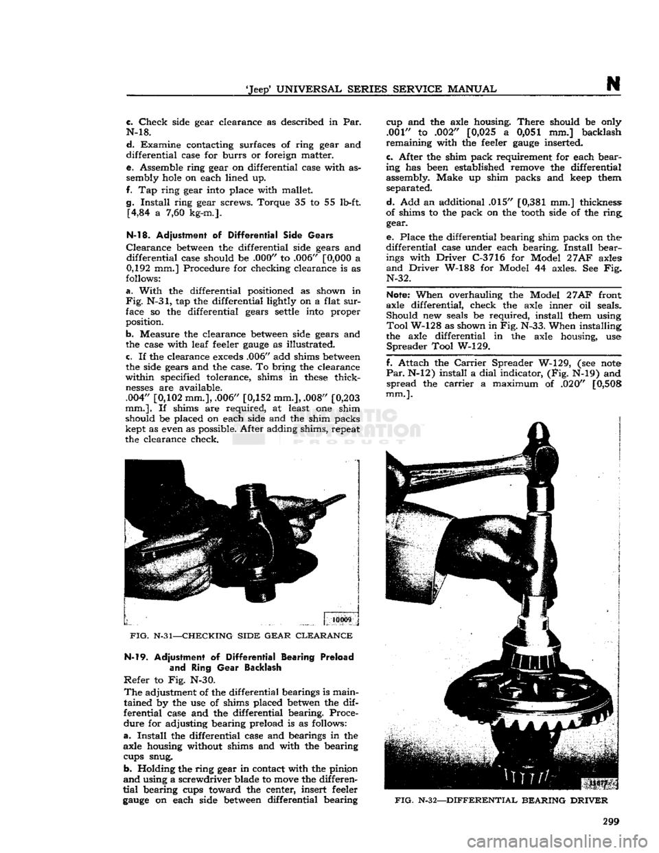
b. Measure the clearance
between
side gears and
the case with leaf feeler
gauge
as illustrated. c. If the clearance
exceds
.006" add shims
between
the side gears and the case. To bring the clearance
within specified tolerance, shims in
these
thick
nesses
are available.
.004"
[0,102
mm.], .006"
[0,152
mm.], .008"
[0,203
mm.].
If shims are required, at least one shim
should be placed on each side and the shim packs kept as even as possible. After adding shims, repeat
the clearance check.
10009
FIG.
N-31—CHECKING SIDE GEAR CLEARANCE N-l9.
Adjustment of
Differential
Bearing Preload
and
Ring
Gear
Backlash
Refer
to Fig. N-30.
The
adjustment of the differential bearings is main
tained by the use of shims placed
betwen
the dif
ferential case and the differential bearing. Proce
dure for adjusting bearing preload is as follows:
a.
Install
the differential case and bearings in the
axle housing without shims and with the bearing
cups snug.
b. Holding the ring gear in contact with the pinipn
and
using a screwdriver blade to
move
the differen
tial
bearing cups toward the center, insert feeler
gauge
on each side
between
differential bearing cup and the axle housing.
There
should be only
.001" to .002"
[0,025
a 0,051 mm.] backlash
remaining with the feeler
gauge
inserted.
c.
After the shim pack requirement for each bear
ing has
been
established remove the differential
assembly. Make up shim packs and
keep
them separated.
d.
Add an additional .015"
[0,381
mm.] thickness:
of shims to the pack on the
tooth
side of the ring gear.
e.
Place the differential bearing shim packs on the
differential case under each bearing.
Install
bear
ings
with
Driver
C-3716 for Model
27AF
axles
and
Driver
W-188 for Model 44 axles. See Fig. N-32.
Note:
When overhauling the Model
27AF
front
axle differential, check the axle inner oil seals. Should new seals be required, install them using
Tool
W-128 as shown in Fig. N-33. When installing
the axle differential in the axle housing, use
Spreader
Tool W-129.
f. Attach the
Carrier
Spreader W-129, (see
note
Par.
N-12) install a
dial
indicator, (Fig. N-19) and spread the
carrier
a maximum of .020"
[0,508
mm.].
FIG.
N-32—DIFFERENTIAL BEARING DRIVER
299
Page 338 of 376
Q
WHEELS
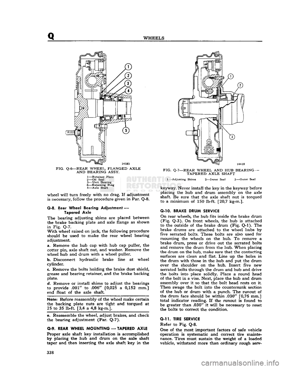
FIG.
Q-6—REAR
WHEEL,
FLANGED
AXLE
AND
BEARING
ASSY.
1—
Retainer
Plate
2— Oil
Seal
3—
Unit
Bearing
4—
Retaining
Ring
5—
Axle
Shaft
wheel
will
turn
freely with no drag. If adjustment
is necessary, follow the procedure given in Par. Q-8.
Q-8.
Rear Wheel Bearing Adjustment
—
Tapered Axle
The
bearing adjusting shims are placed
between
the brake backing plate and axle flange as shown
in
Fig. Q-7.
With
wheel raised on
jack,
the following procedure
should be used to make the
rear
wheel bearing
adjustment.
a.
Remove the hub cap with hub cap puller, the
cotter pin, axle shaft nut, and washer. Remove the
wheel hub and drum with a wheel puller.
b.
Disconnect hydraulic brake line at wheel
cylinder.
c.
Remove the
bolts
holding the brake dust shield, grease and bearing retainer, and the brake backing
plate.
d.
Remove or install shims to adjust the bearings
to provide .001" to .006" [0,025 a 0,152 mm.]
end float of the axle shaft.
Note:
Before reassembly of the wheel make certain
the backing plate nuts are tight and torqued at 25 to 35 lb-ft [3,4 a 4,8 kg-m.].
e. Reassemble the wheel, adjust brakes, and check
the bearing adjustment (Par. Q-7).
0-9.
REAR WHEEL MOUNTING
—
TAPERED AXLE
Proper
axle shaft key installation is accomplished by placing the hub and drum on the axle shaft
taper and then inserting the axle shaft key in the
FIG.
Q-7—REAR
WHEEL
AND HUB
BEARING
—
TAPERED
AXLE
SHAFT
1—-Adjusting
Shims
2—Inner
Seal
3—Outer
Seal
keyway.
Never install the key in the keyway before
placing
the hub and drum assembly on the axle
shaft. Be sure that the axle shaft nut is torqued
to a minimum of 150 lb-ft. [20,7 kg-m.].
O-10.
BRAKE
DRUM
SERVICE
On
rear
wheels, the hub fits inside the brake drum
(Fig.
Q-3). On front wheels, the hub is attached
to the outside of the brake drum (Fig. Q-l). The
brake
drums are attached to the wheel hubs by
five serrated bolts. These
bolts
are also used for
mounting the wheels on the hub. To remove a
brake
drum,
press or drive out the serrated
bolts
and
remove the drum from the hub. When placing
the drum on the hub, make sure that the contacting
surfaces are clean and flat.
Line
up the
holes
in
the drum with
those
in the hub and put the drum
over the shoulder on the hub. Insert five new
serrated
bolts
through the drum and hub and drive
the
bolts
into place solidly. Place a round head of the bolt in a vise. Next, place the hub and drum
assembly over it so that the bolt head rests on it.
Then
swage
the bolt into the countersunk section of the hub or drum with a punch. The runout of
the drum face should be within .030" [0,76 mm.]
total indicator reading. If the runout is found to be greater than .030" it
will
be necessary to reset
the
bolts
to correct the condition.
0-11.
TIRE SERVICE
Refer
to Fig. Q-8.
One
of the most important factors of safe vehicle
operation is systematic and correct tire mainte nance.
Tires
must sustain the weight of a loaded vehicle, withstand more than ordinary rough serv- 338
Page 361 of 376
'Jeep*
UNIVERSAL
SERIES
SERVICE
MANUAL
U
DESCRIPTION
—
Continued
AXLES
W-99* Gauge — Pinion & Ring
Gear
Setting
W-104-B* Puller — Tapered Roller Bearing Removing
W-126* Driver — Pinion Bearing Cup
W-128* Installer — Differential Inner Oil Seal W-129 Spreader — Differential
Carrier
Housing
W-138* Driver & Adapter —
King
Pin Bearing
W-144* Wrench — Wheel Bearing Adjusting Nut W-147* Driver — Pinion Oil Seal W-163* Puller
—-
Axle Shaft Drive Flange
W-186* Driver — Axle Shaft Oil Seal
W-188* Driver — Differential Case Bearing W-251* Puller — Pinion Oil Seal
W-262*
Sleeve
— Pinion Bearing Installing
W-263
Semi-Floating
Rear
Axle Shaft Oil Seal W-264* Driver — Pinion Outer Bearing Cup
W-297* Torque Wrench — Pinion Bearing Adjusting W-343* Remover
85
Installer —
Rear
Axle Bearing (Flanged Axle)
W-344* Installer — Pinion Inner Bearing Cups
C-319-A
Puller —
Rear
Wheel Hub (Tapered Axle Shaft)
C-690 Checking Scale —
King
Pin Bearing Preload DD-914-P Press — Tapered Roller Bearing Removing
DD-914-9 Reducer Ring — Differential & Pinion Bearings (Use with DD-914-P)
C-3
716 Driver — Differential
Carrier
Bearing C-4142
Gear
Rotating Tool —
Trac-Lok
Differential
**Jeep*
exclusive
tool
Steering
Group
C-3646 Puller, Steering Shaft Arm
Brake
Group
W-172 Puller, Parking Brake Drum
U-12.
STflNDfiRD
AND
RECOMMENDED
TOOLS
Tool
Description
ENGINE
W-292
Tester — Cooling
System
Thermostat
C-119 Indicator — Cylinder Bore C-385 Compressor — Piston Ring
C-647 Fixture — Spring Testing
C-823
Hone
— Cylinder Bore Refinishing
C-3012 Reamer — Cylinder Ridge
C-3250 Pliers — Radiator fis Heater
Hose
Wire Clamp
C-3411
Gauge — Pressure & Vacuum
C-3422-A Compressor — E-type Valve Spring
C-3501
Hone
— Cylinder
Deglazing
C-3514
Flusher — Cooling
System
C-3886 Fixture — Carburetor Holding C-3896-A Tachometer — Portable
C-3943 Gauge — Compression Checking
C-3952 Torque Wrench, 150
lb-ft.
Swivel Head C-3953 Stand, Engine Repair
C-3959 Light — Ignition Timing
C-4065 Wrench — Oil Filter Removing
C-4080 Tester — Cooling
System
fig
Pressure Cap
ELECTRICAL
40B Hydrometer — Battery Service
W-291 Tester — Instrument
C-3674
Aimers —
Headlight
(Pair)
C-3829 Tester —
Diode
Polarity
C-3888 Tester — Volt-Ampere C-3950 Tester — 12V 60 Amp. Carbon Pile Resistor 361