service interval JEEP CJ 1953 User Guide
[x] Cancel search | Manufacturer: JEEP, Model Year: 1953, Model line: CJ, Model: JEEP CJ 1953Pages: 376, PDF Size: 19.96 MB
Page 159 of 376

'Jeep'
UNIVERSAL SERIES SERVICE
MANUAL
F2
F2-35.
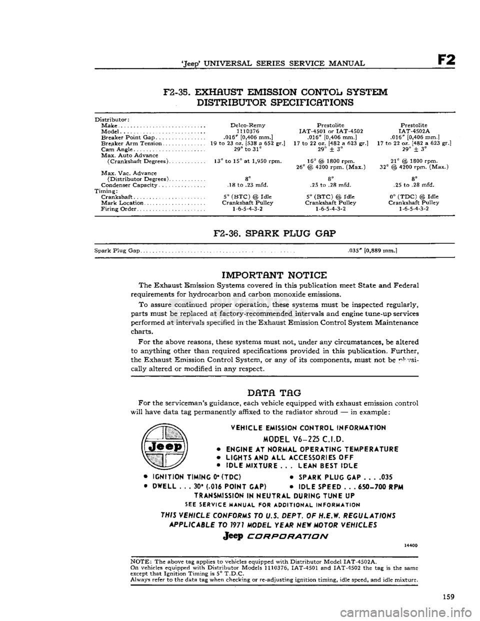
EXHAUST EMISSION CONTOL SYSTEM
DISTRIBUTOR SPECIFICATIONS
Distributor:
Make
Delco-Remy Prestolite Prestolite
Model...
1110376
IAT-4501 or IAT-4502 IAT-4502A
Breaker
Point Gap .016"
[0,406
mm.] .016"
[0,406
mm.] .016"
[0,406
mm.]
Breaker
Arm Tension 19 to 23 oz. [538 a 652 gr.] 17 to 22 oz. [482 a 623 gr.] 17 to 22 oz. [482 a 623 gr.]
Cam
Angle. 29° to 31° 29° + 3° 29° ± 3°
Max.
Auto Advance
(Crankshaft
Degrees). 13° to 15° at 1,950 rpm. 16° (& 1800 rpm. 21° @ 1800 rpm.
26°
@
4200
rpm. (Max.) 32° @
4200
rpm. (Max.)
Max.
Vac. Advance
(Distributor
Degrees) 8° 8° 8°
Condenser Capacity. .18 to .23 mfd. .25 to .28 mfd. .25 to .28 mfd.
Timing:
Crankshaft
5°
(BTC)
@ Idle 5°
(BTC)
© Idle 0°
(TDC)
© Idle
Mark
Location Crankshaft Pulley Crankshaft Pulley Crankshaft Pulley
Firing
Order
1-6-5-4-3-2 1-6-5-4-3-2 1-6-5-4-3-2
F2-36.
SPARK PLUG
GAP
Spark
Plug Gap. .035"
[0,889
mm.]
IMPORTANT
NOTICE
The
Exhaust Emission Systems covered in this publication
meet
State and Federal
requirements for hydrocarbon and carbon
monoxide
emissions.
To
assure continued proper operation,
these
systems
must be inspected regularly,
parts must be replaced at factory-recommended intervals and
engine
tune-up services
performed at intervals specified in the Exhaust Emission Control System Maintenance
charts.
For
the
above
reasons,
these
systems
must not, under any circumstances, be altered
to anything other than required specifications provided in this publication.
Further,
the Exhaust Emission Control System, or any of its components, must not be physi
cally
altered or modified in any respect.
DATA
TAG
For
the serviceman's guidance, each vehicle equipped with exhaust emission control
will
have data tag permanently affixed to the radiator shroud — in example:
VEHICLE EMISSION CONTROL INFORMATION MODEL V6-225 C.I.D.
•
ENGINE
AT
NORMAL OPERATING TEMPERATURE
•
LIGHTS
AND ALL
ACCESSORIES
OFF
•
IDLE MIXTURE
.. .
LEAN BEST IDLE
•
IGNITION TIMING
0*
(TDC)
*
SPARK PLUG
GAP 035
•
DWELL
. . . 30* (.016
POINT
GAP) •
IDLE SPEED
. . .
650- 700
RPM
TRANSMISSION
IN
NEUTRAL DURING TUNE
UP
SEE
SERVICE MANUAL FOR ADDITIONAL INFORMATION
THIS VEHICLE CONFORMS
TO U.S. DEPT. OF H.E.W.
REGULATIONS APPLICABLE
TO
1971
MODEL YEAR
NEW
MOTOR VEHICLES
Jeep
CORPORATION
14400
NOTE:
The
above
tag applies to vehicles equipped with Distributor Model
IAT-4502A.
On
vehicles equipped with Distributor Models
1110376,
IAT-4501 and IAT-4502 the tag is the same
except
that Ignition Timing is 5°
T.D.C.
Always
refer to the data tag when checking or re-adjusting ignition timing, idle speed, and idle mixture.
159
Page 188 of 376

H
ELECTRICAL
SYSTEM
colder plug may be desirable. However, under- or
over-heating is usually caused by factors other than the type of
spark
plugs and the cause should be determined before changing plugs. The design of the
engine
calls for plugs equivalent to Champion
J-8
for F4
engines
and
A.C.
44S or
UJ12Y
Champ
ion for the V6 engines, (as installed in production)
though any factor that consistently affects
engine
operating temperature may cause this requirement
to change. Overheating may be caused by in sufficient tightening of the plug in the head, which interferes with the flow of heat away from the firing
tip.
If this is the case, the plug gasket
will
show very
little flattening. Over-tightening, in
turn,
will
pro duce too easy a heat flow path and result in cold
plug operation.
This
will
be evident by excessive
flattening
and
deformation of the gasket.
Prevailing
temperatures, condition of the cooling system, and
air-fuel
mixture can affect the
engine
operating temperature and should be taken into consideration.
H-34.
GENERATOR
— F4
ENGINE
The
generator is an air-cooled, two-brush unit
which
cannot be adjusted to increase or decrease output. For replacement,
voltage
regulator and generator must be matched for
voltage
and capa
city,
polarity, and common source of manufacture.
Otherwise,
either a
loss
of ampere capacity or a
burned
out generator
will
result. Generators for
these
vehicles are 12-volt. Par. H-l explains the 12-volt system. Refer to the specifications at the
end of this section for information on correct generator rating for a specific model series.
The
circuit
breaker,
voltage
regulator, and current-
limiting
regulator are built into one combination
unit.
Because the regulator and battery are part
of the generator
circuit,
the output of the generator
depends upon the
state
of charge and temperature
of the battery.
With
a discharged battery, the
output
will
be high, decreasing proportionally as the battery
becomes
charged. For service informa
tion covering current regulator see Par. H-41.
H-36.
Generator
Maintenance
A
periodic inspection should be made of the charg
ing
circuit,
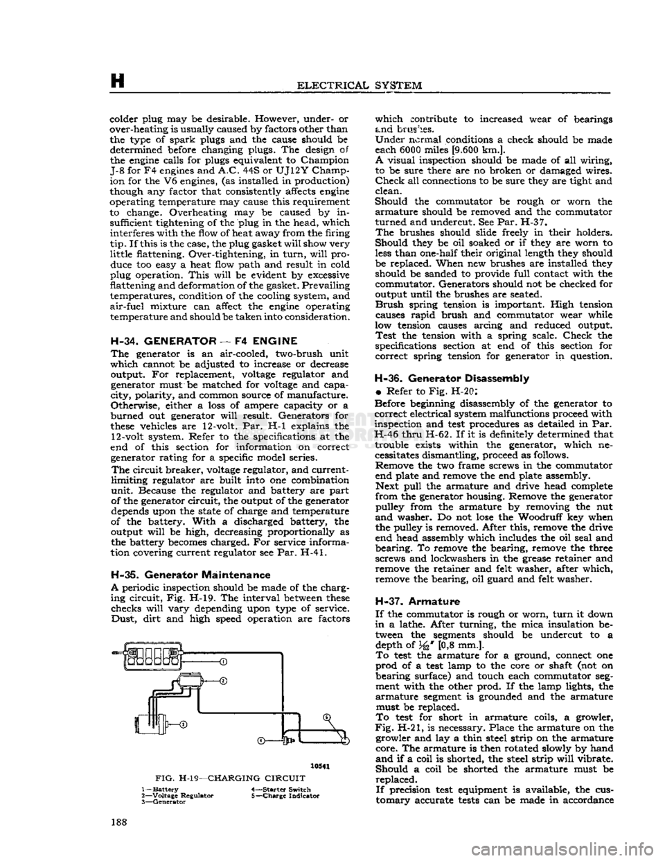
Fig. H-l9. The interval
between
these
checks
will
vary
depending upon type of service.
Dust,
dirt
and high speed operation are factors 10541
FIG.
H-19—CHARGING
CIRCUIT
1—
Battery
4-—Starter Switch
2—
Voltage
Regulator 5-—Charge Indicator
3—
Generator
which
contribute to increased wear of bearings
and
brushes.
Under
normal conditions a check should be made
each 6000 miles
[9.600
km.].
A
visual inspection should be made of all wiring,
to be sure there are no broken or damaged wires.
Check
all connections to be sure they are tight and
clean.
Should
the commutator be rough or worn the
armature
should be removed and the commutator
turned
and undercut. See Par. H-37.
The
brushes should slide freely in their holders.
Should
they be oil soaked or if they are worn to
less
than one-half their original length they should
be replaced. When new brushes are installed they should be sanded to provide
full
contact with the
commutator. Generators should not be checked for
output until the brushes are seated.
Brush
spring tension is important. High tension causes
rapid
brush and commutator wear while
low tension causes arcing and reduced output.
Test
the tension with a spring scale.
Check
the
specifications section at end of this section for
correct
spring tension for generator in question.
H-36.
Generator Disassembly
•
Refer to Fig. H-20:
Before beginning disassembly of the generator to
correct
electrical system malfunctions proceed with
inspection and
test
procedures as detailed in Par.
H-46
thru
H-62. If it is definitely determined that trouble exists within the generator, which necessitates dismantling, proceed as follows. Remove the two frame screws in the commutator
end plate and remove the end plate assembly. Next
pull
the armature and drive head complete
from
the generator housing. Remove the generator pulley from the armature by removing the nut
and
washer. Do not
lose
the Woodruff key when
the pulley is removed. After this, remove the drive
end head assembly which includes the oil seal and
bearing.
To remove the bearing, remove the three
screws and lockwashers in the grease retainer and remove the retainer and felt washer, after which,
remove the bearing, oil guard and felt washer.
H-37.
Armature
If
the commutator is rough or worn,
turn
it down
in
a lathe. After turning, the mica insulation be tween the
segments
should be undercut to a depth of 34* [0,8 mm.].
To
test
the armature for a ground, connect one
prod
of a
test
lamp to the core or shaft (not on
bearing
surface) and touch each commutator
seg
ment with the other prod. If the lamp lights, the
armature
segment
is grounded and the armature must be replaced.
To
test
for short in armature coils, a growler,
Fig.
H-21, is necessary. Place the armature on the growler and lay a thin steel strip on the armature
core.
The armature is then rotated slowly by hand
and
if a coil is shorted, the steel strip
will
vibrate.
Should
a coil be shorted the armature must be
replaced.
If
precision
test
equipment is available, the cus
tomary
accurate
tests
can be made in accordance 188
Page 203 of 376

'Jeep*
UNIVERSAL
SERIES SERVICE
MANUAL
H
13406
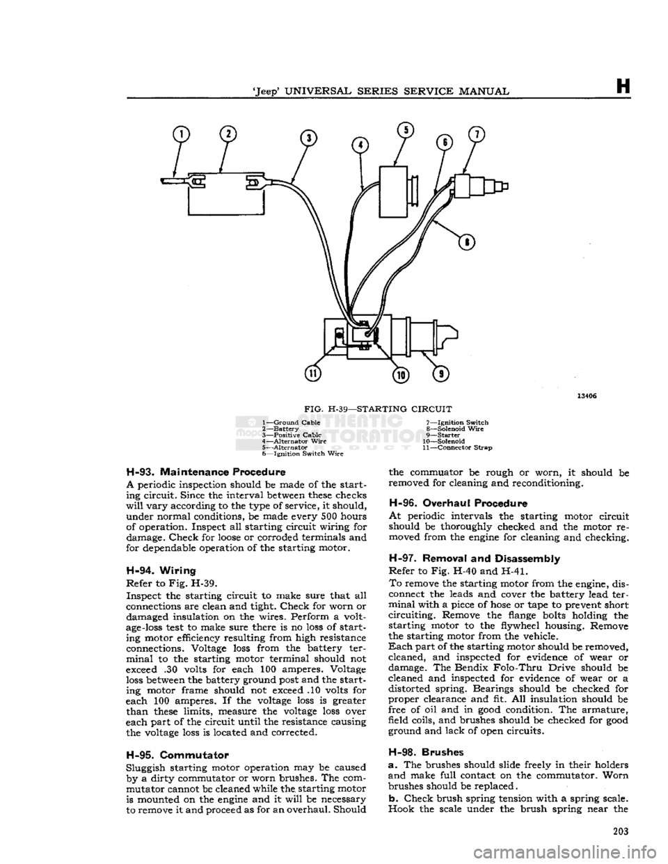
FIG.
H-39—STARTING
CIRCUIT
1—
Ground
Cable
2—
Battery
3—
Positive Cable
4—
Alternator
Wire
5—
Alternator
6— Ignition Switch
Wire
H-93.
Maintenance Procedure
A
periodic inspection should be made of the start ing circuit. Since the interval
between
these
checks
will
vary according to the type of service, it should, under normal conditions, be made every 500 hours
of operation. Inspect all starting circuit wiring for damage.
Check
for
loose
or corroded terminals and
for dependable operation of the starting motor.
H-94.
Wiring
Refer
to Fig. H-39. Inspect the starting circuit to make sure that all
connections are clean and tight.
Check
for worn or damaged insulation on the wires. Perform a volt
age-loss
test
to make sure there is no
loss
of start ing motor efficiency resulting from high resistance
connections. Voltage
loss
from the battery ter
minal
to the starting motor terminal should not
exceed .30 volts for each 100 amperes. Voltage
loss
between
the battery ground
post
and the starting motor frame should not exceed .10 volts for
each 100 amperes. If the
voltage
loss
is greater
than
these
limits, measure the
voltage
loss
over
each part of the circuit until the resistance causing the
voltage
loss
is located and corrected.
H-95.
Commutator
Sluggish starting motor operation may be caused by a dirty commutator or worn brushes. The commutator cannot be cleaned while the. starting motor is mounted on the
engine
and it
will
be necessary
to remove it and proceed as for an overhaul. Should 7— Ignition Switch
8— Solenoid
Wire
9—
Starter
10— Solenoid
11—
Connector
Strap
the commuator be rough or worn, it should be
removed for cleaning and reconditioning.
H-96.
Overhaul Procedure
At
periodic intervals the starting motor circuit
should be thoroughly checked and the motor re moved from the
engine
for cleaning and checking.
H-97.
Removal and Disassembly
Refer
to Fig. H-40 and H-41.
To
remove the starting motor from the engine, dis
connect the leads and cover the battery lead ter
minal
with a piece of
hose
or tape to prevent short
circuiting.
Remove the flange
bolts
holding the starting motor to the flywheel housing. Remove
the starting motor from the vehicle.
Each
part of the starting motor should be removed, cleaned, and inspected for evidence of wear or
damage. The Bendix
Folo-Thru
Drive should be
cleaned and inspected for evidence of wear or a distorted spring. Bearings should be checked for
proper clearance and fit. All insulation should be
free of oil and in
good
condition. The armature,
field coils, and brushes should be checked for
good
ground and lack of open circuits.
H-98.
Brushes
a.
The brushes should slide freely in their holders
and
make full contact on the commutator. Worn
brushes should be replaced.
b.
Check
brush spring tension with a spring scale.
Hook the scale under the brush spring near the 203
Page 303 of 376

'Jeep*
UNIVERSAL
SERIES SERVICE
MANUAL
N
scribed
in
Pars.
N-ll through N-l9 for standard
axles, with the exception of the following torque
recommendations. Torque the differential case
bearing
cap screws 70 to 90 lb-ft. [9,7 a 12,4 kg-m.]
and
the cover screws 15 to 25 lb-ft. [2,1 a 3,4
kg-m.].
The ring gear screws on axles with Powr-
Lok
differentials should be torqued as follows:
Model
30 and 44 axles 35 to 55 lb-ft. [4,84 a 7,60 kg-m.].
N-24. TRAC-LOK DIFFERENTIAL
As
optional equipment
Trac-Lok
Model 44 differen
tial
is available on all Jeep Universal vehicles equipped with semi-float flanged axle shafts.
A
conventional differential transmits all of the
ring
gear torque through the differential gears to the axle shafts. Torque is at all
times
equal on the axle shafts, and if one wheel slips, the other wheel
can
only put out as much torque as the slipping
wheel.
The
Trac-Lok
differential is similar,
except
that
part
of the torque from the ring gear is trans mitted through clutch packs
between
the side gears
and
differential case. The multiple disc clutches
with
radial
grooves
on the plates and concentric
grooves
on the discs are
engaged
by a preload
from
Belleville springs, plus separating forces from
the side gears as torque is applied through the
ring
gear.
The
Trac-Lok
construction permits differential action when required for turning corners and transmits equal torque to both
wheels
when driving
straight
ahead. However, when one wheel tries to spin due to leaving the ground, a patch of ice,
etc., the clutch packs automatically provide more
torque to the wheel which is not trying to spin.
It
can be
seen
then that the
Trac-Lok
differential
resists wheel spin on bumpy roads and provides
more pulling power when one wheel tries to slip.
In
many cases of differences in traction, pulling
power
will
be automatically provided until both
wheels
start to slip.
In
diagnosis of vehicle operators' complaints, it
is important to recognize two things:
a.
If, with unequal traction, both
wheels
slip, the
Trac-Lok
has
done
all it can possibly do.
b.
In extreme cases of differences in traction, the
wheel with least traction may spin after the
Trac-
Lok
has transferred as much torque as possible
to the non-slipping wheel.
N-25.
Lubrication
The
Trac-Lok
differential requires a special
lubri
cant
and ordinary multipurpose gear lubricants
MUST
NOT be used. Use only 'Jeep* Differential
Oil,
Part
No. 94557.
Trac-Lok
differential may be cleaned only by disassembling the unit and wiping with clean rags. Do not flush the
Trac-Lok
unit.
Note:
The
Trac-Lok
differential is serviced at the
same time intervals as the standard differential.
N-26.
Trouble
Symptoms
If
noises
or roughness, such as chatter, are present
in
turning corners, the probable cause is incorrect
or
contaminated lubricant.
Before any differential is removed and disassem
bled for chatter complaints, the correctness of
lubri
cant
can and should be determined.
A
complete
lubricant
drain,
and
refill
with specified
Limited
Slip Differential lubricant
will
usually
correct
chatter.
The
following procedure is recommended to ensure
complete
removal of old lubricant.
a.
Warm
the lubricant by vehicle road operation,
or
5 minutes of operation in gear at 30 mph with
both
wheels
off the ground on a hoist.
Caution:
Never place the transmission in gear with
the
engine
running when only one wheel of a
Limited
Slip Differential equipped vehicle is raised.
The
vehicle might drive itself off the
jack
and produce damage or
injury.
b.
Drain
lubricant while
warm.
Remove
drain
plug
or
cover to
drain
completely. If cover is removed,
it
may be necessary to replace gasket at this time.
c.
Refill
axle with specified
Limited
Slip Differen
tial
lubricant.
d.
Operate the vehicle for approximately ten miles
[16,09
km.], making at least ten figure 8 turns
to flush the old lubricant out of the clutch packs.
e.
Repeat
steps
b, c, and d, making sure to replace
the cover gasket if required in
step
c.
f. It is possible that slight chatter, requiring ad
ditional
vehicle operation, may remain after
step
e. If chatter persists after 100 miles
[160,9
km.]
of vehicle operation, or remains severe after
step
e above, disassembly and repair
will
be necessary.
N-27.
Unit
Inoperative
Proper
performance and capabilities of
Limited
Slip
Differentials are
often
misunderstood. No
precise
methods
of measuring
Limited
Slip Dif
ferential
performance are generally available in the field. A functioning unit can be determined by
relatively
simple vehicle operational
tests,
as
follows:
a.
Place one wheel on
good
dry pavement, and the
other on ice, mud, grease, etc.
b.
Gradually
increase
engine
rpm to obtain maxi
mum
traction
prior
to "break-a-way." The ability
to
move
the vehicle
effectively
will
demonstrate
proper
performance.
c.
If extremely slick surfaces, such as ice or grease,
are
used
some
question may exist as to proper per
formance at
step
b. In
these
extreme cases a prop
erly
performing
Limited
Slip Differential
will
pro
vide greater "pulling" power by lightly applying
the parking brake.
N-23.
Trac-Lok
Differential Disassembly
and
Reassembly
It
is recommended that the
complete
axle assembly
be removed from the vehicle, when it
becomes
necessary to remove the
Trac-Lok
from the hous
ing.
Refer to Par. N-3 and N-12 for removal of axle shafts and differential case from axle housing. 303