weight JEEP CJ 1953 User Guide
[x] Cancel search | Manufacturer: JEEP, Model Year: 1953, Model line: CJ, Model: JEEP CJ 1953Pages: 376, PDF Size: 19.96 MB
Page 62 of 376
D
HURRICANE
F4
ENGINE d.
Remove the intake valve adjusting screw lock-
nuts from each of the rocker arm valve lash ad
justing
screws. Remove the screws from the rocker
arms.
D-76.
Inspection and
Repair
Run
a round wire brush through the bore of the
rocker
arm shaft and clean out the drilled oil holes.
Clean
out the oil
holes
in the rocker arm shaft
brackets,
and the oil
holes
and
grooves
in the bores
of the rocker arm.
Inspect
the diameter of the shaft at the rocker arm
bearing
areas. Replace the shaft if there are scores
or
abrasion marks along the length of the shaft.
Check
the shaft for alignment by rolling it across
a
smooth level surface. If the shaft
will
not
roll
freely, or if it rolls with a bumping motion, the
shaft is out of alignment and must be replaced.
Inspect
the threads of the adjusting screw
hole
in
the rocker arms and if necessary clean with a
proper
size tap. Replace the adjusting screw lock-
nut or the adjusting screw if either part is damaged
or
deformed.
Inspect
the threads in the tapped
hole
in the top
of the rocker arm shaft brackets and if necessary
clean
with a proper size tap. Replace the bracket
if
either side is worn or scored.
D-77.
Reassembly
a.
Install
two rocker arm shaft plugs, one in each
end of the shaft. Slide two
rocker
arm
shaft brackets
onto
the center of the shaft. Align the tapped
holes
in
the brackets with the drilled
holes
in the top of
the shaft and install the rocker arm shaft lock
screws,
making sure the points of the screws enter
the drilled
holes
in the shaft.
b.
Screw the intake valve adjusting screws into
the rocker arms and install the locknuts.
c.
The rocker arms are paired; that is, two of the
arms
are angled to the right and two are angled to
the left. One of each type is used on each end of
the rocker arm shaft. Slide a rocker arm with the
adjusting
screw end of the rocker arm angling
away
from the bracket
onto
the shaft so that the
adjusting
screw is on the same side of the shaft
as the mounting
hole
in the bracket.
d.
Temporarily
secure the end bracket in place by
installing
a rocker arm cover stud in the tapped
opening in the top of the support.
e. Assemble the parts on the
opposite
end of the
rocker
arm shaft repeating
steps
c and d above.
D-78. ENGINE REASSEMBLY
The
engine
reassembly procedure in the following
paragraphs
is given in the sequence to be followed
when the
engine
is being completely overhauled.
Individual
inspection,
repair,
and fitting operations
previously covered in detail are made throughout
the reassembly procedure. The reassembly pro
cedure
does
not cover accessories. If a new cylinder
block
fitted with pistons is used, many of the
operations
will
not be required.
Mount
the cylinder block in an
engine
repair stand.
If
an
engine
stand is not available, perform the fol
lowing reassembly operation in a manner designed to protect personnel against an accident and the
engine
and its parts against damage.
Note:
During
engine
reassembly, use Perfect Seal
Aerosol
Spray
Sealer
Part
No.
994757
on all
engine
gaskets to ensure against vacuum, oil, gasoline and
water
leaks. Apply to head gaskets, valve covers,
water
pumps, oil pan gaskets, radiator and heater
hose
connections, felt gaskets, gasoline and oil line
connections, stud bolts,
spark
plug threads, and
grease retainer washers. Refer to manufacturer's in
structions on container for proper application pro
cedure.
D-79.
Install
Oil
Gallery
Plug
Coat
plug threads with a suitable sealing compound
and
install the plugs in the front and
rear
ends of
the oil gallery in the cylinder block and the
rear
end of the cylinder head. Torque the plugs 20 to 25 lb-ft. [2,8 a 3,4 kg-m.].
There
is also a pipe plug
(}/g,f
[3,2 mm.] slotted, headless) in the opening in the main oil gallery inside the cylinder block at No. 2 cylinder and another pipe plug
(}/g
"
square-head) in the opening
in
the oil passage directly below the oil pump intake
passage. If
these
two pipe plugs were removed,
make
certain they are reinstalled in the locations
described above or the counterweight of the
crankshaft
might strike the projecting head of the
square-head
plug.
D-80.
Install
Tappets
Turn
the block upside down. Beginning at the
rear
end of the cylinder block, install the intake
and
exhaust valve tappets in the tappet bores in the cylinder block in the following order: one
exhaust, two intake, two exhaust, two intake, and
finally
one exhaust valve tappet.
Check
the tappet to bore fit of each tappet as it
is installed in the block. If the stem-to-block
clearance
tolerance of .0005" to .002" [0,0127 a
0,051 mm.] is
exceeded
install a new tappet fitting
within
this tolerance or ream the bore to accomo date the next oversize tappet which is available
in
.004" oversize.
D-81.
Install
Camshaft and
Thrust
Plate
Lubricate
all camshaft bearings and cam surfaces generously with clean, light
engine
oil.
Carefully,
so not to damage or score the camshaft front bear
ing,
install the camshaft, locating it properly in the bearings. Do not allow the
rear
end of the camshaft to strike sharply against the expansion plug
installed
in the
rear
end of the bore.
Install
the camshaft thrust plate. Slide the thrust
plate spacer
onto
the end of the camshaft with the
beveled inner
edge
of the spacer facing the cam
shaft. If the same camshaft is being reinstalled,
install
any shims previously removed. These shims
are
placed
between
the camshaft shoulder and the
spacer.
Torque the thrust plate attaching
bolts
20
to 26 lb-ft. [2,8 a 3,6 kg-m.].
End
play of the camshaft is determined by running
clearance
between
the
rear
face of the camshaft
gear and the thrust plate. The standard clearance 62
Page 67 of 376
'Jeep'
UNIVERSAL
SERIES SERVICE
MANUAL
D
Lubricate
the connecting rod bearing surfaces
generously with
engine
oil and install the bearing
cap with the numbered side matched to the num
bered side of the connecting rod. Torque the nuts
evenly 35 to 45 lb-ft. [4,8 a 6,2 kg-m.]. The con
necting rod cap nuts are locked with stamped nuts.
Used
stamped nuts should be discarded and re
placed with new
ones.
These locking stamped nuts
should be installed with the flat face toward the
connecting rod nut.
Turn
the locking nut finger
tight and then 34
turn
more with a wrench. Refer
to Par. D-36 for detailed information on fitting pistons and rings in the cylinder bores.
D-96.
Install
Crankshaft
Pulley
Align
the keyway in the pulley with the woodruff key installed in the crankshaft. Drive the pulley
onto
the crankshaft and secure it in place with
the crankshaft pulley nut. Insert a block of wood
between
one of the counterweights on the
crank
shaft and the side of the cylinder block to prevent the crankshaft from turning, then tighten the nut.
D-97.
Install
Oil Pan
Before installing the oil pan, make a final internal
inspection particularly making certain that the
inside of the cylinder block is clean. Apply a thin
coat of gasket paste on the oil pan. Place the new
oil
pan gasket in position. Set the oil pan in posi
tion on the cylinder block and install the oil pan.
Torque
the attaching
bolts
12 to 15 lb-ft. [1,7 a 2,1
kg-m.].
Install
the oil pan
drain
plug and gasket
and
tighten the plug securely.
D-98.
Install
Cylinder
Head
Make
certain that the entire top of the cylinder
block
assembly, the lower surface of the cylinder
head,
and the cylinder head gasket are clean. Blow
all
dirt
or carbon out of the blind tapped bolt
holes
in
the cylinder block before the cylinder head and gasket are installed. Using aerosol spray sealer
Part
No. 994757, spray a thincoat on both surfaces
of the head gasket, position the new cylinder head gasket with the crimped
edges
of the gasket metal down (See Fig. D-31).
This
gasket position allows a
positive seal along the narrow surfaces of the
cylin
der
head
between
the combustion chambers and
eliminates the possibility of burning combustion
10102
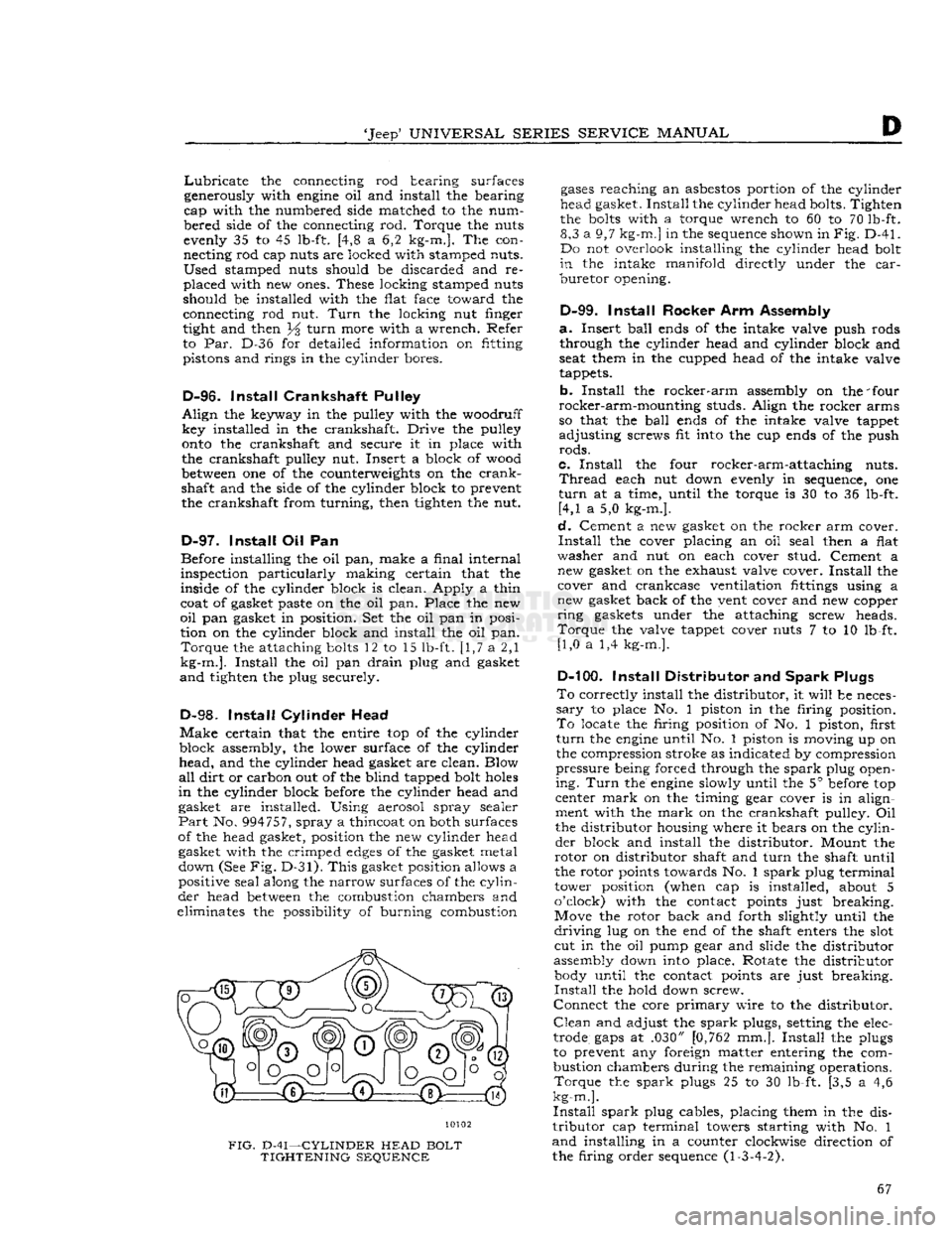
FIG.
D-41—CYLINDER
HEAD
BOLT
TIGHTENING
SEQUENCE
gases
reaching
an
asbestos
portion of the cylinder
head gasket.
Install
the cylinder head bolts. Tighten
the
bolts
with a torque wrench to 60 to 70 lb-ft. 8,3 a 9,7
kg-m.]
in the sequence shown in
Fig.
D-41.
Do not overlook installing the cylinder head bolt
in
the intake
manifold
directly under the
car
buretor
opening.
D-99.
Install
Rocker Arm Assembly
a.
Insert
ball
ends of the intake valve push rods through the cylinder head and cylinder block and
seat them in the cupped head of the intake valve
tappets.
b.
Install
the
rocker-arm
assembly on the 'four
rocker-arm-mounting
studs. Align the rocker arms
so that the
ball
ends of the intake valve tappet
adjusting
screws fit into the cup ends of the push
rods.
c.
Install
the four rocker-arm-attaching nuts.
Thread
each nut down evenly in sequence, one
turn
at a time, until the torque is 30 to 36 lb-ft. [4,1 a 5,0 kg-m.].
d.
Cement a new gasket on the rocker arm cover.
Install
the cover placing an oil seal then a flat
washer
and nut on each cover stud. Cement a new gasket on the exhaust valve cover.
Install
the cover and crankcase ventilation fittings using a
new gasket back of the vent cover and new copper
ring
gaskets under the attaching screw heads.
Torque
the valve tappet cover nuts 7 to 10 lb-ft. [1,0 a 1,4 kg-m.].
D-100.
Install
Distributor and
Spark
Plugs
To
correctly install the distributor, it
will
be neces
sary
to place No. 1 piston in the firing position.
To
locate the firing position of No. 1 piston, first
turn
the
engine
until No. 1 piston is moving up on
the compression stroke as indicated by compression
pressure
being forced through the
spark
plug open
ing.
Turn
the
engine
slowly until the 5° before top
center
mark
on the timing gear cover is in align
ment with the
mark
on the crankshaft pulley. Oil
the distributor housing where it bears on the
cylin
der
block and install the distributor. Mount the
rotor
on distributor shaft and
turn
the shaft until
the rotor points towards No. 1
spark
plug terminal
tower position (when cap is installed, about 5
o'clock) with the contact points just breaking.
Move the rotor back and forth slightly until the
driving
lug on the end of the shaft enters the slot cut in the oil pump gear and slide the distributor
assembly down into place. Rotate the distributor body until the contact points are just breaking.
Install
the hold down screw.
Connect
the core
primary
wire to the distributor.
Clean
and adjust the
spark
plugs, setting the elec
trode
gaps
at .030" [0,762 mm.].
Install
the plugs
to prevent any foreign matter entering the com
bustion chambers during the remaining operations.
Torque
the
spark
plugs 25 to 30 lb-ft. [3,5 a 4,6
kg-m.].
Install
spark
plug cables, placing them in the dis
tributor
cap terminal towers starting with No. 1
and
installing in a counter clockwise direction of
the firing order sequence (1-3-4-2). 67
Page 71 of 376
'Jeep*
UNIVERSAL
SERIES
SERVICE
MANUAL
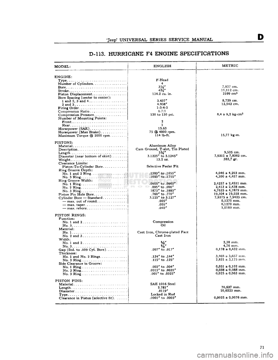
D D-l 13. HURRICANE
F4
ENGINE SPECIFICATIONS
MODEL:
ENGLISH
ENGINE:
Type
Number of Cylinders
Bore
Stroke
Piston Displacement...........
Bore
Spacing (center to center): 1 and 2, 3 and 4
2 and 3
Firing
Order Compression Ratio Compression Pressure... .
Number of Mounting Points:
Front
Rear
Horsepower (SAE)
Horsepower (Max Brake) Maximum Torque @
2000
rpm.
PISTONS:
Material
Description
Length
,.
Diameter (near
bottom
of
skirt).
Weight.
Clearance
Limits:
Piston-To-Cylindcr
Bore
Ring
Groove Depth:
No. 1 and 2 Ring No. 3 Ring
Ring
Groove Width:
No. 1 Ring No. 2 Ring
No. 3 Ring
Piston Pin Hole Bore
Cylinder
Bore — Standard.....
—
max. out of round
F-Head
4
W
134.2 cu. in.
3.437"
4.938"
1-3-4-2
6.7:1
120 to 130 psi.
2
1
15.63
@
4000
rpm. 114 lb-ft. 75
-
max. taper..
-
max. rebore.
PISTON RINGS:
Function:
No. 1 and 2 No. 3. .
Material:
No. 1. .
No. 2 and 3
Width;
No. 1 and 2
No. 3. . . .
Gap
(Std. to .009 Cyl. Bore).
Thickness:
No. 1 and No. 2 Rings....
No. 3 Ring
Side Clearance in Groove:
No. 1 Ring No. 2 Ring
No. 3 Ring
PISTON
PINS:
Material
Length
Diameter
Type
Clearance
in Piston
(selective
fit).
Aluminum
Alloy
Gam
Ground, T-slot, Tin Plated
3.1225*
to
3.1245*
13.5 oz.
Selective Feeler Fit
.1593" to .1655"
.1693" to .1755"
.0955" to .0965" .095" to .096"
1875" to .1885" .760" to .770"
3.125"
to
3.127"
.005" .005" .040"
Compression
Oil
Cast
Iron,
Chrome-plated Face
Cast
Iron
.007" to .017"
.134" to .144" .115" to .125"
.002" to .004"
.0015" to .0035" .001" to .0025"
SAE
1016 Steel
2.781"
.8119"
Locked
in Rod
.0001"
to .0003"
METRIC
7,937
cm.
11,112
cm. 2199 cm*
8,729
cm.
12,542
cm.
8,4 a 9,2 kg-cm2
15,77 kg-m.
9,525
cm.
7,9311
a
7,9362
cm.
382,7
gr.
4,046
a
4,203
mm.
4,300
a
4,457
mm.
2,4257
a
2,4511
mm. 2,413 a
2,438
mm.
4,7625
a
4,7879
mm.
19,304
a
19,558
mm.
7,9375
a
7,9425
cm.
0,1270
mm.
0,1270
mm.
1,0160
mm.
2,38 mm.
4,76 mm.
0,178 a
0,432
mm.
3,403
a
3,657
mm. 2,821 a 3,175 mm.
0,051 a 0,102 mm.
0,038
a
0,088
mm.
0,025
a
0,063
mm.
70,637
mm.
20,6223
mm.
0,0025
a
0,0076
mm. 71
Page 72 of 376
D
HURRICANE
F4
ENGINE
D-l
13
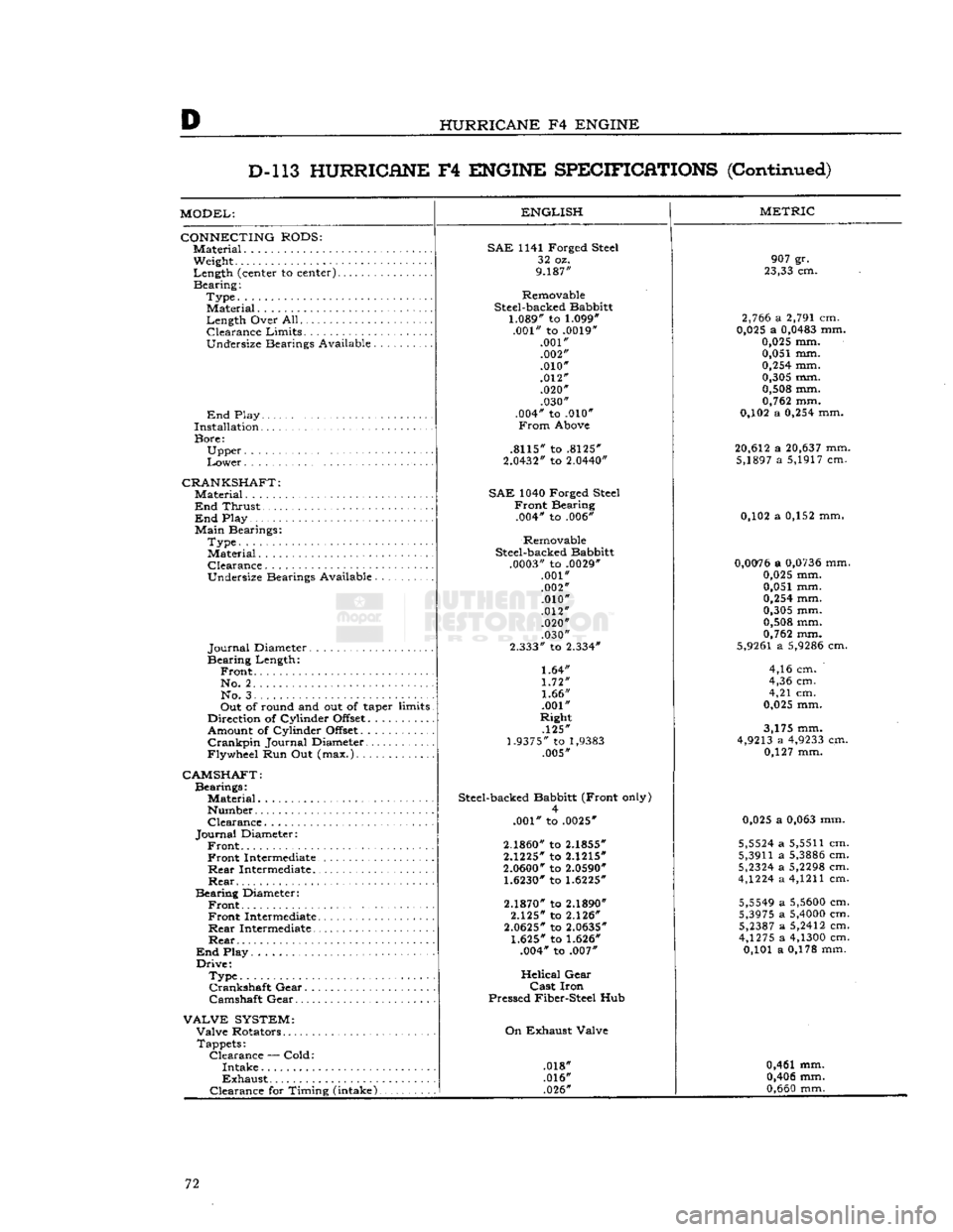
HURRICHNE
F4
ENGINE
SPECIFICATIONS
(Continued)
MODEL:
CONNECTING
RODS:
Material.
Weight
Length
(center to
center)......
Bearing:
Type.
Material
Length
Over
All
Clearance
Limits.
..........
Undersize
Bearings
Available
End
Play
Installation
Bore:
Upper
Lower
CRANKSHAFT:
Material....................
End
Thrust
End
Play
Main
Bearings:
Type.
Material
Clearance
Undersize
Bearings
Available
Journal
Diameter
Bearing
Length:
Front.
No.
2. . .
No.
3
Out
of
round
and out of taper
limits
Direction
of
Cylinder
Offset..........
Amount
of
Cylinder
Offset
Crankpin
Journal
Diameter
Flywheel
Run Out
(max.)
ENGLISH
CAMSHAFT:
Bearings:
Material..........
Number
Clearance.
Journal
Diameter:
Front Front
Intermediate.
Rear
Intermediate..
Rear
Bearing
Diameter:
Front Front
Intermediate.
Rear
Intermediate..
Rear
End
Play
Drive:
Type.............
Crankshaft
Gear.
. .
Camshaft
Gear
VALVE
SYSTEM:
Valve
Rotators
Tappets:
Clearance
—
Cold:
Intake
Exhaust
Clearance
for
Timing
(intake).
SAE
1141
Forged
Steel
32 oz.
9.187"
Removable
Steel-backed
Babbitt
1.089" to 1.099"
.001"
to .0019"
.001" .002"
.010"
.012" .020" .030"
.004"
to .010"
From
Above
.8115"
to .8125"
2.0432"
to 2.0440"
SAE
1040
Forged
Steel
Front
Bearing
.004*
to .006*
Removable
Steel-backed
Babbitt
.0003"
to .0029*
.001"
.002" .010"
.012" .020"
.030"
2.333"
to 2.334"
1.64"
1.72"
1.66"
.001"
Right
.125"
1.9375" to
1,9383
.005"
Steel-backed
Babbitt
(Front
only) 4
.001"
to .0025"
2.1860" to 2.1855"
2.1225"
to 2.1215"
2.0600" to 2.0590" 1.6230" to 1.6225"
2.1870" to 2.1890"
2.125"
to 2.126"
2.0625"
to 2.0635"
1.625" to 1.626"
.004*
to .007"
Helical
Gear
Cast
Iron
Pressed
Fiber-Steel
Hub
On
Exhaust
Valve
.018*
.016* .026"
METRIC
907
gr.
23,33 cm.
2,766 a 2,791 cm.
0,025 a 0,0483 mm.
0,025 mm. 0,051 mm.
0,254
mm.
0,305 mm. 0,508 mm.
0,762 mm.
0,102 a
0,254
mm.
20,612 a 20,637 mm. 5,1897 a 5,1917 cm.
0,102 a 0,152 mm,
0,0076 a 0,0736 mm. 0,025 mm.
0,051 mm.
0,254
mm.
0,305 mm.
0,508 mm.
0,762 mm.
5,9261
a 5,9286 cm.
4,16 cm.
4,36 cm.
4,21 cm.
0,025 mm.
3,175 mm.
4,9213 a 4,9233 cm. 0,127 mm.
0,025 a
0,063
mm.
5,5524 a
5,5511
cm.
5,3911
a 5,3886 cm.
5,2324 a 5,2298 cm.
4,1224 a
4,1211
cm.
5,5549 a 5,5600 cm.
5,3975 a 5,4000 cm. 5,2387 a 5,2412 cm.
4,1275 a 4,1300 cm. 0,101 a 0,178 mm.
0,461 mm. 0,406 mm.
0,660
mm. 72
Page 76 of 376
Dl
DAUNTLESS
V-6
ENGINE
DM.
GENERAL
This
section describes service and repair of the
Dauntless V-6 engine. The
engine
code
number shown in
Fig.
A-4 is provided to identify the Daunt
less
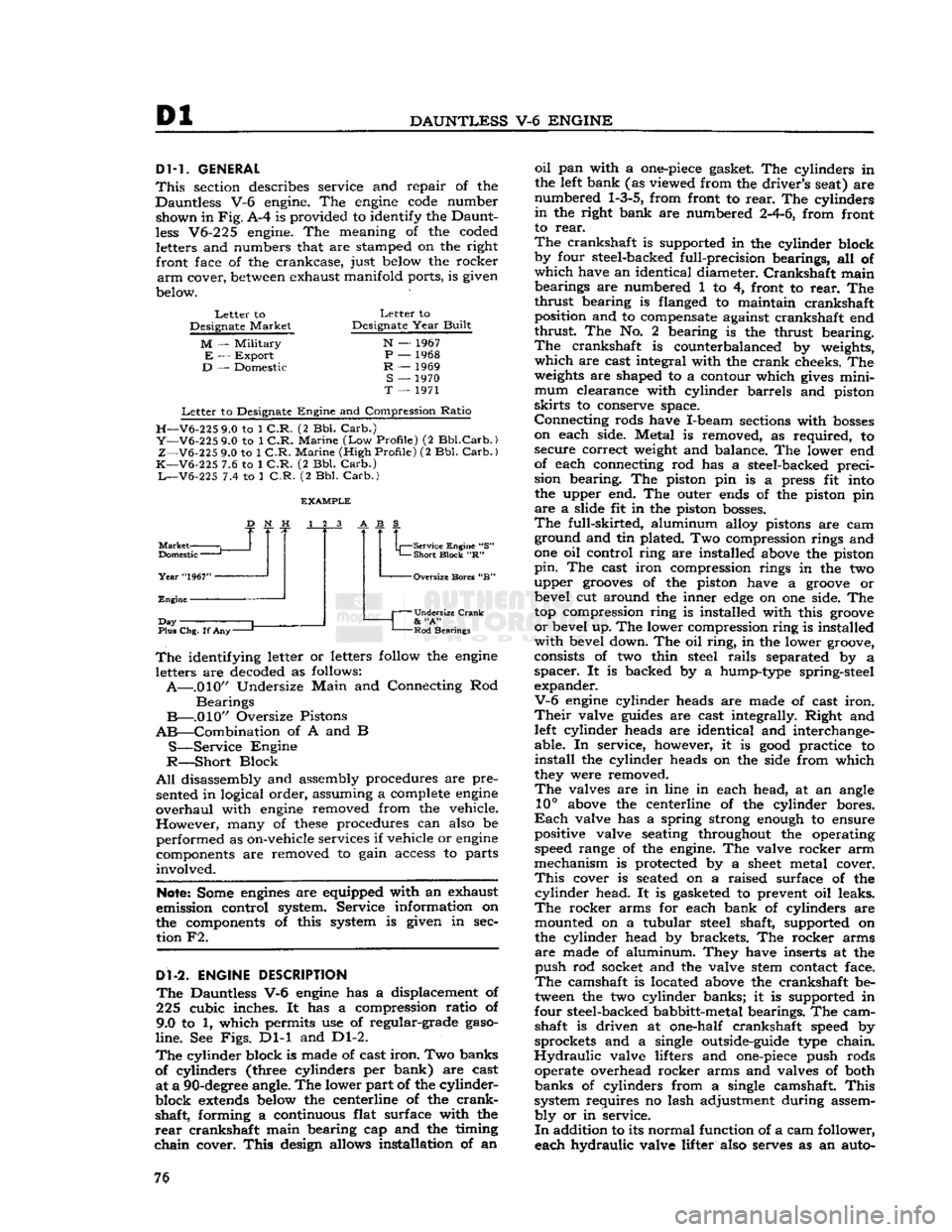
V6-225 engine. The meaning of the coded letters and numbers that are stamped on the right front face of the crankcase, just below the rocker
arm
cover,
between
exhaust manifold ports, is given
below.
Letter
to
Designate
Market
M
—
Military
E
—
Export
D
— Domestic
Letter
to
Designate
Year
Built
N
— 1967
P
— 1968
R
— 1969
S
— 1970
T
— 1971
Letter
to Designate
Engine
and Compression
Ratio
H—V6-225
9.0 to 1
C.R.
(2 Bbl.
Carb.)
Y—V6-225
9.0 to 1
C.R.
Marine
(Low
Profile)
(2
Bbl.Carb.)
Z—V6-225
9.0 to 1
C.R.
Marine
(High
Profile)
(2 Bbl.
Carb.)
K—V6-225
7.6 to 1
C.R.
(2 Bbl.
Carb.)
L—V6-225
7.4 to 1
C.R.
(2 Bbl.
Carb.)
Market
Domestic
—
Year
"1967"
Engine
J
Day
Plus Chg. If
Any-
Service Engine "S"
Short
Block
"R" -Oversize Bores "B"
Undersize Crank
&
"A"
Rod
Bearings
The
identifying letter or letters follow the
engine
letters are decoded as follows:
A—.010"
Undersize
Main
and Connecting Rod
Bearings
B—.010"
Oversize Pistons
AB—Combination
of A and B
S—Service
Engine
R—Short
Block
All
disassembly and assembly procedures are pre sented in logical order, assuming a complete
engine
overhaul
with
engine
removed from the vehicle.
However,
many of
these
procedures can also be
performed as on-vehicle services if vehicle or
engine
components are removed to gain access to parts
involved.
Note:
Some
engines
are equipped with an exhaust
emission control system. Service information on
the components of this system is given in sec tion F2.
Dl-2.
ENGINE
DESCRIPTION
The
Dauntless V-6
engine
has a displacement of
225 cubic inches. It has a compression ratio of
9.0 to 1, which permits use of regular-grade
gaso
line.
See
Figs.
Dl-1 and Dl-2.
The
cylinder block is made of cast
iron.
Two banks
of cylinders (three cylinders per bank) are cast at a
90-degree
angle. The lower part of the cylinder-
block
extends
below the centerline of the
crank
shaft, forming a continuous flat surface with the
rear
crankshaft main bearing cap and the timing
chain
cover.
This
design allows installation of an
oil
pan with a
one-piece
gasket. The cylinders in
the left bank (as viewed from the driver's seat) are
numbered
1-3-5,
from front to
rear.
The cylinders
in
the right bank are numbered
2-4-6,
from front
to
rear.
The
crankshaft is supported in the cylinder block
by four steel-backed full-precision bearings, all of
which
have an identical diameter.
Crankshaft
main bearings are numbered 1 to 4, front to
rear.
The
thrust
bearing is flanged to maintain crankshaft position and to compensate against crankshaft end
thrust
The No. 2 bearing is the thrust bearing.
The
crankshaft is counterbalanced by weights,
which
are cast integral with the
crank
cheeks. The
weights
are shaped to a contour which
gives
mini
mum
clearance with cylinder barrels and piston
skirts
to conserve space.
Connecting
rods have I-beam sections with
bosses
on each side. Metal is removed, as required, to secure correct weight and balance. The lower end
of each connecting rod has a steel-backed preci
sion bearing. The piston pin is a press fit into the upper end. The outer ends of the piston pin
are
a slide fit in the piston
bosses.
The
full-skirted, aluminum alloy pistons are cam ground and tin plated. Two compression rings and
one oil control ring are installed above the piston
pin.
The cast iron compression rings in the two
upper
grooves
of the piston have a
groove
or bevel cut around the inner
edge
on one side. The
top compression ring is installed with this
groove
or
bevel up. The lower compression ring is installed
with
bevel down. The oil
ring,
in the lower groove,
consists of two thin steel
rails
separated by a
spacer.
It is backed by a hump-type spring-steel
expander.
V-6
engine
cylinder heads are made of cast
iron.
Their
valve
guides
are cast integrally. Right and left cylinder heads are identical and interchange
able. In service, however, it is
good
practice to
install
the cylinder heads on the side from which
they were removed.
The
valves are in line in each head, at an angle
10°
above the centerline of the cylinder bores.
Each
valve has a spring strong enough to ensure
positive valve seating throughout the operating speed range of the engine. The valve rocker arm
mechanism is protected by a
sheet
metal cover.
This
cover is seated on a raised surface of the
cylinder
head. It is gasketed to prevent oil leaks.
The
rocker arms for each bank of cylinders are mounted on a tubular steel shaft, supported on
the cylinder head by brackets. The rocker arms
are
made of aluminum. They have inserts at the
push
rod socket and the valve stem contact face.
The
camshaft is located above the crankshaft be
tween the two cylinder banks; it is supported in
four steel-backed babbitt-metal bearings. The cam shaft is driven at one-half crankshaft speed by
sprockets and a single outside-guide type chain.
Hydraulic
valve lifters and
one-piece
push rods operate overhead rocker arms and valves of both
banks
of cylinders from a single camshaft.
This
system requires no lash adjustment during assem
bly
or in service.
In
addition to its normal function of a cam follower,
each hydraulic valve lifter also serves as an auto- 76
Page 79 of 376
'Jeep*
UNIVERSAL SERIES SERVICE
MANUAL
Dl
12710
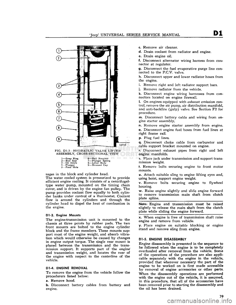
FIG.
D1
-3—HYDRAULIC VALVE
LIFTER
ASSEMBLY, CROSS-SECTIONAL VIEW
1—
Snap
Ring
6—Ball Retainer
2— Rod
Seat
7—Plunger Spring
3—
Oil
Inlets
8—Lifter
Body
4—
Plunger
9—Bronzed
Cap
5— Feed
Hole
sages
in the block and cylinder head.
The
water cooled system is pressurized to provide efficient
engine
cooling. It consists of a centrifugal-
type water pump, mounted on the timing chain cover, and is driven by the
engine
fan pulley. The
pump provides coolant flow equally to both
cylin
der banks under control of a thermostat. Coolant
flow is around the cylinders and through the
cylinder
head to dispel the heat of combustion in
the engine.
Dl-3.
Engine Mounts
The
engine-transmission unit is mounted to the chassis at three points by rubber pads. The two
front mounts are bolted to the
engine
cylinder
block and the frame members. These mounts sup port most of the
engine
weight, and absorb
vibra
tion which would otherwise be caused by changes
in
engine
output torque. The single
rear
mount is
placed
between
the transmission and the trans mission support. It supports part of the engine'
and
transmission weight, and locates the
rear
of
the
engine
with respect to the centerline of the
vehicle.
Dl-4. ENGINE REMOVAL
To
remove the
engine
from the vehicle follow the
procedurers listed below:
a.
Remove hood. b. Disconnect battery cables from battery and
engine. c. Remove air cleaner.
d.
Drain
coolant from radiator and engine.
e.
Drain
engine
oil.
f. Disconnect alternator wiring harness from con nector at regulator.
cj.
Disconnect the fuel evaporative purge line con nected to the
P.C.V.
valve.
h.
Disconnect upper and lower radiator
hoses
from
the engine.
i.
Remove right and left radiator support
bars,
j.
Remove radiator from the vehicle.
k.
Disconnect
engine
wiring harnesses from con
nectors located on
engine
firewall.
I.
On
engines
equipped with exhaust emission con
trol,
remove the air pump, air distribution manifold,
and
anti-backfire (gulp) valve. See Section F2 for
procedure.
m.
Disconnect battery cable and wiring from en
gine
starter assembly.
n.
Remove
engine
starter assembly from engine,
o.
Disconnect
engine
fuel
hoses
from fuel lines at
right
frame
rail,
p. Plug fuel lines.
q.
Disconnect choke cable from carburetor and cable support bracket mounted on engine,
r.
Disconnect exhaust pipes from right and left
engine
manifolds.
s. Place
jack
under transmission and support trans
mission weight.
f. Remove
bolts
securing
engine
to front motor mounts.
u.
Attach suitable sling to
engine
lifting
eyes
and,
using hoist, support
engine
weight.
v. Remove
bolts
securing
engine
to flywheel housing.
w. Raise
engine
slightly and slide
engine
forward
to remove transmission main shaft from clutch plate spline.
Note:
Engine and transmission must be raised
slightly to release the main shaft from the clutch
plate while sliding the
engine
forward.
x. When
engine
is free of transmission shaft raise
engine
and remove from vehicle,
y. Place
engine
on suitable blocking or
engine
stand and remove sling from engine.
Dl-5.
ENGINE DISASSEMBLY
Engine
disassembly is presented in the sequence to be followed when the
engine
is to be completely
overhauled after removal from the vehicle. Some of the operations of the procedure are also applicable separately with the
engine
in the vehicle,
provided that wherever necessary the part of the
engine
to be worked on is first made accessible by removal of
engine
accessories or other parts.
When
the disassembly operations are performed
with
the
engine
out of the vehicle, it is assumed,
in
this procedure, that all of the accessories have
been removed
prior
to starting the disassembly and
the oil has been drained.
Page 85 of 376
'Jeep*
UNIVERSAL
SERIES SERVICE
MANUAL
Dl
12713
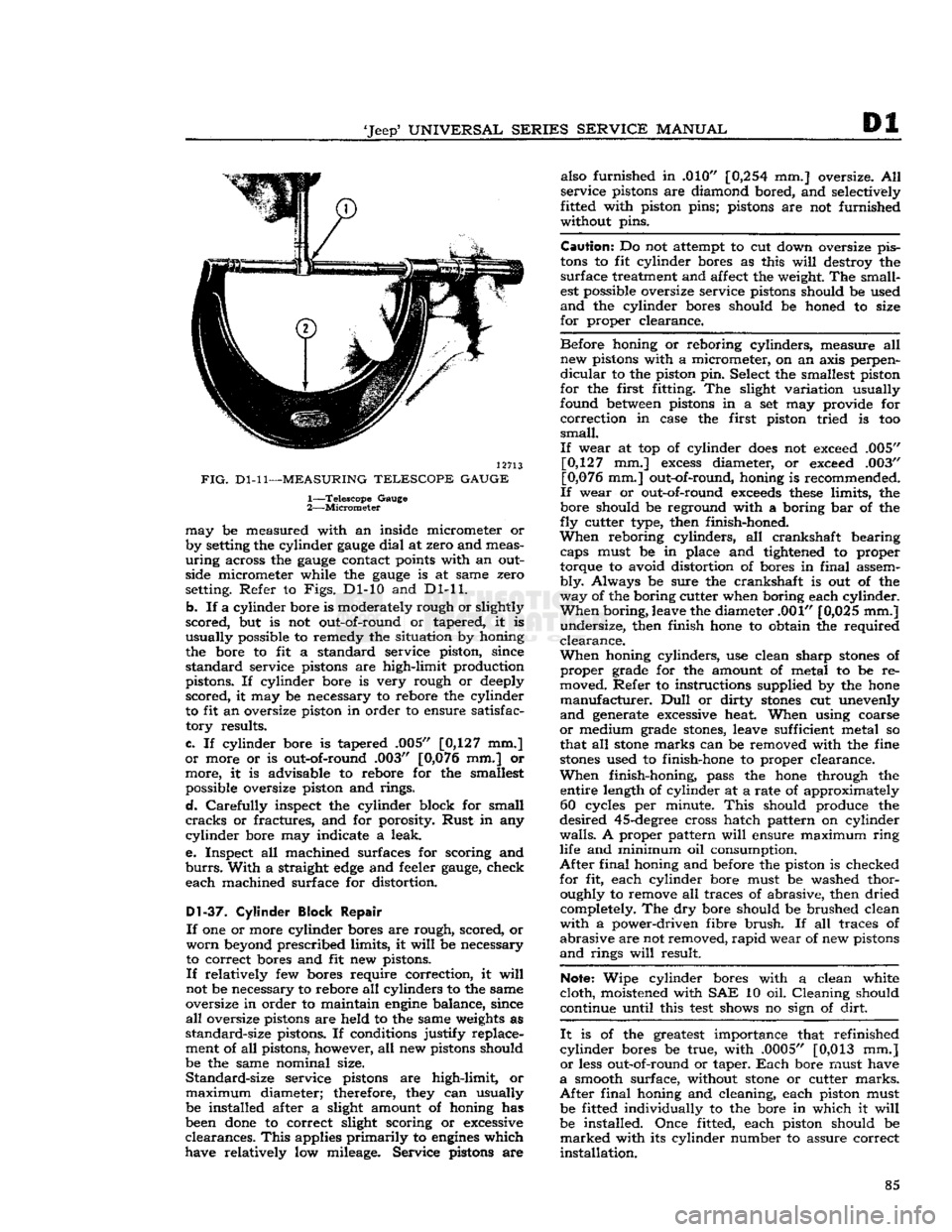
FIG.
Dl-11—MEASURING
TELESCOPE GAUGE
1—
Telescope
Gauge
2—
Micrometer
may
be measured with an inside micrometer or
by setting the cylinder
gauge
dial
at zero and meas
uring
across the
gauge
contact points with an outside micrometer while the
gauge
is at same zero
setting. Refer to
Figs.
Dl-10 and Dl-11.
b.
If a cylinder bore is moderately rough or slightly
scored,
but is not out-of-round or tapered, it is
usually
possible to remedy the situation by honing
the bore to fit a standard service piston, since
standard
service pistons are high-limit production
pistons. If cylinder bore is very rough or deeply
scored,
it may be necessary to rebore the cylinder
to fit an oversize piston in order to ensure satisfac
tory
results.
c.
If cylinder bore is tapered .005" [0,127 mm.]
or
more or is out-of-round .003" [0,076 mm.] or
more,
it is advisable to rebore for the smallest possible oversize piston and rings.
d.
Carefully
inspect the cylinder block for small
cracks
or fractures, and for porosity.
Rust
in any
cylinder
bore may indicate a leak.
e.
Inspect all machined surfaces for scoring and
burrs.
With
a straight
edge
and feeler
gauge,
check
each
machined surface for distortion.
D1-37.
Cylinder Block Repair
If
one or more cylinder bores are rough, scored, or
worn
beyond prescribed limits, it
will
be necessary
to correct bores and fit new pistons.
If
relatively few bores require correction, it
will
not be necessary to rebore all cylinders to the same
oversize in order to maintain
engine
balance, since
all
oversize pistons are held to the same weights as
standard-size
pistons. If conditions justify replace
ment of all pistons, however, all new pistons should
be the same nominal size.
Standard-size
service pistons are high-limit, or
maximum
diameter; therefore, they can usually be installed after a slight amount of honing has
been
done
to correct slight scoring or excessive
clearances.
This
applies
primarily
to
engines
which
have relatively low mileage. Service pistons are also furnished in .010"
[0,254
mm.] oversize. All
service
pistons are diamond bored, and selectively
fitted with piston pins; pistons are not furnished
without pins.
Caution:
Do not attempt to cut down oversize pis
tons
to fit cylinder bores as this
will
destroy the
surface
treatment and affect the weight. The small
est possible oversize service pistons should be used
and
the cylinder bores should be honed to size
for
proper clearance.
Before
honing or reboring cylinders, measure all new pistons with a micrometer, on an axis perpen
dicular
to the piston pin. Select the smallest piston
for
the first fitting. The slight variation usually
found between pistons in a set may provide for
correction
in case the first piston tried is too
small.
If
wear at top of cylinder
does
not exceed .005" [0,127 mm.]
excess
diameter, or exceed .003"
[0,076 mm.] out-of-round, honing is recommended.
If
wear or out-of-round
exceeds
these
limits, the
bore should be reground with a boring bar of the
fly
cutter type, then finish-honed.
When
reboring cylinders, all crankshaft bearing caps must be in place and tightened to proper
torque to avoid distortion of bores in
final
assem
bly.
Always be sure the crankshaft is out of the
way
of the boring cutter when boring each cylinder.
When
boring, leave the diameter .001" [0,025 mm.]
undersize,
then finish hone to obtain the required
clearance.
When
honing cylinders, use clean sharp
stones
of
proper
grade for the amount of metal to be re
moved. Refer to instructions supplied by the hone
manufacturer.
Dull
or dirty
stones
cut unevenly
and
generate excessive heat. When using coarse
or
medium grade
stones,
leave sufficient metal so
that all
stone
marks can be removed with the fine
stones
used to finish-hone to proper clearance.
When
finish-honing, pass the hone through the entire length of cylinder at a rate of approximately 60 cycles per minute.
This
should produce the
desired
45-degree
cross hatch pattern on cylinder
walls.
A proper pattern
will
ensure maximum
ring
life and minimum oil consumption.
After
final
honing and before the piston is checked
for
fit, each cylinder bore must be washed thor oughly to remove all traces of abrasive, then dried completely. The dry bore should be brushed clean
with
a power-driven fibre
brush.
If all traces of
abrasive
are not removed,
rapid
wear of new pistons
and
rings
will
result.
Note:
Wipe cylinder bores with a clean white
cloth,
moistened with SAE 10 oil. Cleaning should
continue until this
test
shows no sign of
dirt.
It
is of the greatest importance that refinished
cylinder
bores be true, with .0005" [0,013 mm.]
or
less out-of-round or taper.
Each
bore must have
a
smooth surface, without
stone
or cutter
marks.
After
final
honing and cleaning, each piston must be fitted individually to the bore in which it
will
be installed. Once fitted, each piston should be
marked
with its cylinder number to assure correct
installation.
85
Page 96 of 376
Dl
DAUNTLESS
V-6
ENGINE
Note:
During
engine
reassembly, use Perfect Seal
Aerosol
Spray Sealer
Part
No.
994757
on all en
gine
gaskets to ensure against vacuum, oil, gasoline
and
water leaks. Apply to head gaskets, valve covers, water pumps, oil pan gaskets, radiator and
heater
hose
connections, felt gaskets, gasoline and
oil
line connections, stud bolts, spark plug threads,
and
grease retainer washers. Refer to manufac
turer's
instructions on container for proper appli
cation procedure.
Dl-72.
Cylinder
Block
and Crankshaft
Rear
Oil Seals
Braided
fabric seals are pressed into
grooves
of
cylinder
block and
rear
main bearing cap, to
rear
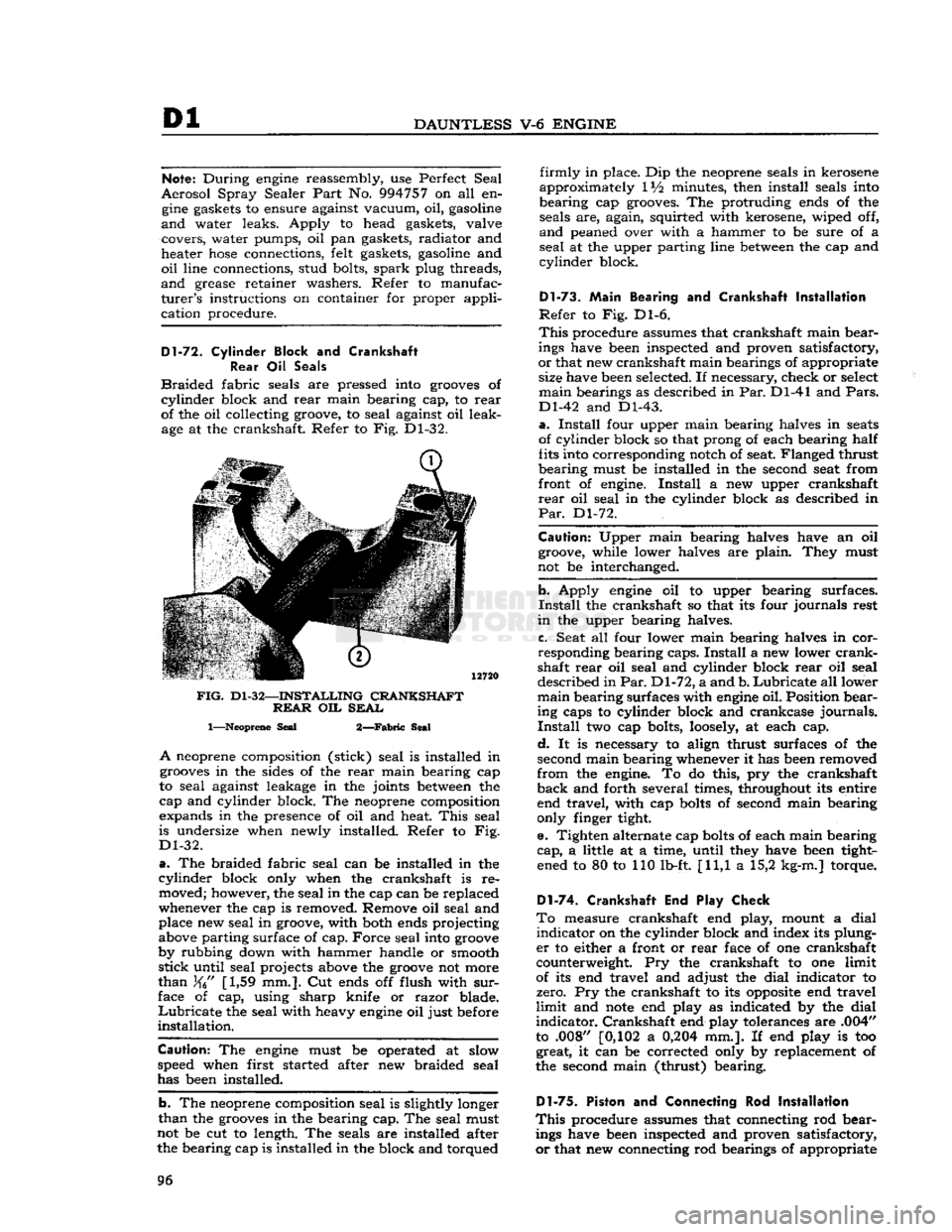
of the oil collecting groove, to seal against oil leak age at the crankshaft. Refer to Fig. Dl-32.
FIG.
Dl-32—INSTALLING
CRANKSHAFT REAR
OIL
SEAL
1—Neoprene
Seal
2—Fabric
Seal
A
neoprene composition (stick) seal is installed in
grooves
in the sides of the
rear
main bearing cap
to seal against leakage in the joints
between
the
cap and cylinder block. The neoprene composition
expands in the presence of oil and heat.
This
seal
is undersize when newly installed. Refer to Fig.
Dl-32.
a.
The braided fabric seal can be installed in the
cylinder
block only when the crankshaft is re moved; however, the seal in the cap can be replaced
whenever the cap is removed. Remove oil seal and place new seal in groove, with both ends projecting
above parting surface of cap. Force seal into
groove
by rubbing down with hammer handle or smooth
stick
until seal projects above the
groove
not more
than
[1,59 mm.]. Cut ends off flush with
sur
face of cap, using sharp knife or razor blade.
Lubricate
the seal with heavy
engine
oil just before
installation.
Caution:
The
engine
must be operated at slow
speed when first started after new braided seal
has been installed.
b. The neoprene composition seal is slightly longer
than
the
grooves
in the bearing cap. The seal must
not be cut to length. The seals are installed after the bearing cap is installed in the block and torqued
firmly
in place. Dip the neoprene seals in kerosene
approximately IV2 minutes, then install seals into
bearing cap grooves. The protruding ends of the seals are, again, squirted with kerosene, wiped off,
and
peaned over with a hammer to be sure of a
seal
at the upper parting line
between
the cap and
cylinder
block.
Dl-73.
Main
Bearing and Crankshaft
Installation
Refer
to Fig. Dl-6.
This
procedure assumes that crankshaft main bear
ings have been inspected and proven satisfactory,
or
that new crankshaft main bearings of appropriate size have been selected. If necessary, check or select
main
bearings as described in Par. Dl-41 and
Pars.
Dl-42 and Dl-43.
a.
Install
four upper main bearing halves in
seats
of cylinder block so that prong of each bearing half
fits into corresponding notch of seat. Flanged thrust
bearing must be installed in the second seat from
front of engine.
Install
a new upper crankshaft
rear
oil seal in the cylinder block as described in
Par.
Dl-72.
Caution:
Upper main bearing halves have an oil groove, while lower halves are plain. They must
not be interchanged.
b. Apply
engine
oil to upper bearing surfaces.
Install
the crankshaft so that its four journals rest
in
the upper bearing halves.
c. Seat all four lower main bearing halves in cor
responding bearing caps.
Install
a new lower
crank
shaft
rear
oil seal and cylinder block
rear
oil seal
described in
Par.
Dl-72, a and b.
Lubricate
all lower
main
bearing surfaces with
engine
oil. Position bear ing caps to cylinder block and crankcase journals.
Install
two cap bolts,
loosely,
at each cap.
d.
It is necessary to align thrust surfaces of the
second main bearing whenever it has been removed
from
the engine. To do this, pry the crankshaft
back
and forth several times, throughout its entire end travel, with cap
bolts
of second main bearing
only finger tight.
e. Tighten alternate cap
bolts
of each main bearing
cap,
a little at a time, until they have been tight ened to 80 to 110 lb-ft. [11,1 a 15,2 kg-m.] torque.
D1-74. Crankshaft End Play Check
To
measure crankshaft end play, mount a dial
indicator
on the cylinder block and index its plung
er
to either a front or
rear
face of one crankshaft
counterweight. Pry the crankshaft to one limit
of its end travel and adjust the dial indicator to
zero. Pry the crankshaft to its
opposite
end travel
limit
and
note
end play as indicated by the dial
indicator.
Crankshaft end play tolerances are .004"
to .008" [0,102 a
0,204
mm.]. If end play is too great, it can be corrected only by replacement of
the second main (thrust) bearing.
Dl-75.
Piston and Connecting Rod
Installation
This
procedure assumes that connecting rod bear ings have been inspected and proven satisfactory,
or
that new connecting rod bearings of appropriate 96
Page 114 of 376
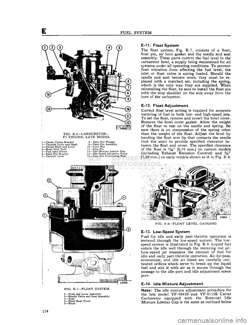
FUEL
SYSTEM
14261
FIG.
E-6—CARBURETOR—
F4 ENGINE,
LATE
MODEL 1—
Choke
Clamp Bracket
2—
Throttle
Lever
and Shaft
3—
Choke
Shaft and
Lever
4—
Bowl
Vent Tube
5—
Fuel
Inlet Elbow
6—
Dash
Pot Bracket 7—
Throttle
Lever
8—
Dash
Pot Plunger
9—
Dash
Pot Assembly
10—
Lock
Nut
11— Stop Pin
1
2—Idle Mixture
Limiter
Cap
13—
Idle
Speed Adjusting Screw 14—
Fast
Idle Connecting Rod
E-11.
Float System
The
float system, Fig. E-7, consists of a float,
float
pin,
air horn gasket and the
needle
and seat assembly. These parts control the fuel level in the
carburetor
bowl, a supply being maintained for all
systems under all operating conditions. To prevent
float
vibration
from affecting the fuel level, the
inlet or float valve is spring loaded. Should the
needle
and seat
become
worn, they must be re
placed
with a matched set, including the spring,
which
is the only way they are supplied. When
reinstalling
the float, be sure to install the float pin
with
the
stop
shoulder on the side away from the bore of the carburetor.
E-12.
Float Adjustment
Correct
float level setting is required for accurate
metering of fuel in both low- and high-speed jets.
To
set the float, remove and invert the bowl cover. Remove the bowl cover gasket. Allow the weight
of the float to rest on the
needle
and spring. Be
sure
there is no compression of the spring other
than
the weight of the float. Adjust the level by
bending the float arm lip that contacts the
needle
(not the arm) to provide specified clearance be
tween the float and cover. The specified clearance of the float is
L74\F
[6,74 mm.] on current models
(including
Exhaust
Emission Control) and [7,93 mm.] on early models shown as A in
Fig.
E-8.
FIG.
E-7—FLOAT SYSTEM
1—
Float
and
Lever
Assembly
2—
Needle
Valve and Seat Assembly
3—
Vent
4—
Float
Bowl Cover 5—
Float
7 '.. j
io8Si
i
FIG.
E-8—FLOAT
LEVEL
GAUGING
E-13.
Low-Speed System
Fuel
for idle and early part-throttle operation is
metered through the low-speed system. The low-
speed system is illustrated in Fig.
E-9.
Liquid
fuel enters the idle well through the metering rod jet.
Low-speed
jet measures the amount of fuel for
idle and early part-throttle operation. Air-by-pass,
economizer, and idle air bleed are carefully
cali
brated
orifices which serve to break up the liquid
fuel
and mix it with air as it
moves
through the passage to the idle port and idle adjustment screw
port.
E-14.
Idle Mixture Adjustment
Note:
The idle mixture adjustment procedure for
the late model
YF-4941S
and
YF-6115S
Carter
Carburetor
equipped with the
External
Idle
Mixture
Limiter
Cap is the same as outlined below 114
Page 116 of 376
E
FUEL
SYSTEM
pressing downward on metering rod) or
seats
be
fore the metering rod arm makes flat contact with the pump lifter link, make adjustment by bending
the lip on the metering rod arm.
E-17.
Choke System
The
choke system consists of a manually-operated
choke valve, a fast-idle connecting rod, and a fast-
idle arm. The choke valve is offset-spring loaded to prevent over-choking during the starting warm-
up period. When the choke valve is moved to a closed position for starting, the fast idle connector
rod
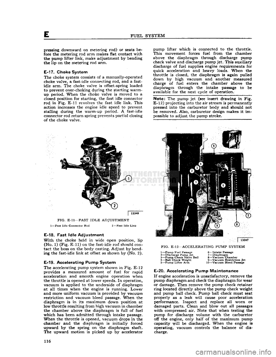
in Fig. E-ll revolves the fast idle link.
This
action increases the
engine
idle speed to prevent stalling during the warm-up period. A fast-idle
connector rod return spring prevents partial closing
of the choke valve. pump lifter which is connected to the throttle.
This
movement forces fuel from the chamber
above the diaphragm through discharge pump check valve and discharge pump jet.
This
auxiliary discharge of fuel supplies
engine
requirements for
quick
acceleration and heavy loads. When the
throttle is closed, the diaphragm is again pulled
down by high vacuum and another measured
charge of fuel enters the chamber above the
diaphragm
through the intake passage to be
available for the next cycle of operation.
Note:
The pump jet (see insert drawing in Fig.
E-12)
projecting into the air stream is permanently pressed into the carburetor body and should not
be removed. Also, carburetor design makes it im possible to adjust the pump stroke.
FIG.
E-ll—FAST
IDLE
ADJUSTMENT
1—Fast
Idle
Connector Rod
2—Fast
Idle
Link
E-18.
Fast
Idle Adjustment
With
the choke held in wide open position, lip (No. 1) (Fig.
E-ll)
on the fast-idle rod should con
tact the
boss
on the body casting. Adjust by bend
ing the fast-idle link at
offset
as shown by (No. 2).
E-19.
Accelerating Pump System
The
accelerating pump system shown in Fig. E-12
provides a measured amount of fuel for rapid acceleration and smooth
engine
operation when
the throttle is opened at lower speeds. In operation,
vacuum
is applied to the underside of diaphragm
at all times when the
engine
is running.
Lower
and
more uniform vacuum is provided by vacuum
restriction
and vacuum bleed passage. When the
diaphragm
is in its maximum down position at
low throttle resulting from high vacuum in chamber the chamber above the diaphragm is full of fuel
which
has been admitted through intake passage.
When
the throttle is opened, vacuum drops in the
chamber and the diaphragm is initially forced
upward
by the spring on the diaphragm shaft.
The
upward motion is picked up by accelerator
|
13347
FIG.
E-12—ACCELERATING
PUMP
SYSTEM
1—
Pump
Fuel
Passage
6—Intake
Passage
2—
Discharge
Pump Jet 7—Diaphragm
3—
Pump
Check
Valve
Ball
8—Vacuum Chamber 4—
Bail
Check
Weight
9—Vacuum
Restriction
Jet
5—
Pump
Lifter
Arm 10—Vacuum Bleed Passage
E-20.
Accelerating Pump Maintenance
If
engine
acceleration is unsatisfactory, remove the
pump diaphragm and check the diaphragm for wear
or
damage. Then remove the pump check retainer
ring
located directly above the pump check weight
and
pump ball check. Pump ball check must seat
properly
as a leak
will
cause poor acceleration performance. Inspect and replace all worn or
damaged parts.
Clean
and blow out all passages
with
compressed air.
Note
that when testing the pump for discharge volume with the carburetor
off the engine, only half of the maximum pump capacity
will
be discharged. When the
engine
is
operating, vacuum controls the balance of dis charge. 116