wheel size JEEP CJ 1953 User Guide
[x] Cancel search | Manufacturer: JEEP, Model Year: 1953, Model line: CJ, Model: JEEP CJ 1953Pages: 376, PDF Size: 19.96 MB
Page 339 of 376

'Jeep'
UNIVERSAL
SERIES
SERVICE
MANUAL
Q
ice, provide maximum safety over all
types
of
terrain,
and furnish the medium on which the
vehicle can be maneuvered with ease. Although
there are other
elements
of tire service, inflation maintenance is the most important and in many
instances the most neglected. The tire pressure should be maintained for safe operation. An under- inflated tire is dangerous as too much flexing can
cause breakage of the casing. Overinflation in time
may
cause a blowout.
Upon
careful inspection of tires, it may be found
that improper wheel alignment, balance, grabbing
brakes,
poor driving habits, fast cornering or other
conditions are the cause of wear. Such conditions
should be corrected.
a.
UNDERINFLATION
Underinflation
distorts the normal contour of the
tire
body and the tire
bulges
or "bellies out" with
an
extreme flexing action.
This
wears the tread at the
edges
more than the center and generates
excessive internal heat, weakening the cords and
resulting
in bruises, broken cords or ply separation.
Underinflation
also leads to rim bruises as in sufficient resistance is provided to prevent the tire
from
being jammed against the rim and crushed
or
cut when the tire strikes a
curb,
rock, or rut.
b.
OVERINFLATION
When
a tire is
overinf
lated,
increased tension caused by excessive pressure prevents proper deflection of
the sidewalls.
This
results in wear in the center of the tread and the tire also
loses
its ability to absorb
road
shocks. Under this increased
strain,
cords in the tread area eventually snap under impact, causing a casing break.
c.
MISALIGNMENT
WEAR
Excessive
wheel camber causes the tires to run at an angle to the road when camber is incorrect
it
will
cause excessive wear on one side of the
tire
tread.
Front
wheels should be straight ahead or toe-in slightly. When there is excessive toe-in or
toe-out,
tires
will
revolve with a side motion and scrape
the tread rubber off.
Front
tires
will
show wear on the outside with too great a toe-in condition
and
on the inside with a
toe-out
condition.
d.
BALANCE
Cupping
and bald spotting of tires is associated
with
wear on a vehicle driven mostly at high-way
speeds
without the recommended tire rotation and
with
unbalance conditions.
Q-12.
Tire
Care
Note;
For satisfactory 4-wheel drive operation, a
4-wheel drive vehicle
MUST
be equipped with the same size tires of equal circumference on all
four wheels. The tires must then be inflated to
proper
factory recommended pressures at all times.
Tire
pressure, tire rotation, wheel balance, and wheel alignment are the four vital factors that in
fluence the
extent
of tire life and the
ease
and safety of vehicle control.
Four
of the most common
tire
troubles are:
a.
Excessive wear around the outer
edges
resulting
from
underinflation.
b.
Excessive wear in the center of the tread re
sulting from overinflation.
c.
Tire
tread worn on one side indicating wheels
need realigning.
d.
Cuplike
depressions on one side of the tread
indicating
wheels need balancing.
If
the vehicle normally carries a
full
load, two to
four psi. [0,14 a 0,28 kg-m2] can be added to the
recommended air pressures. But, remember that adding air with a light load means a harsher ride,
doesn't
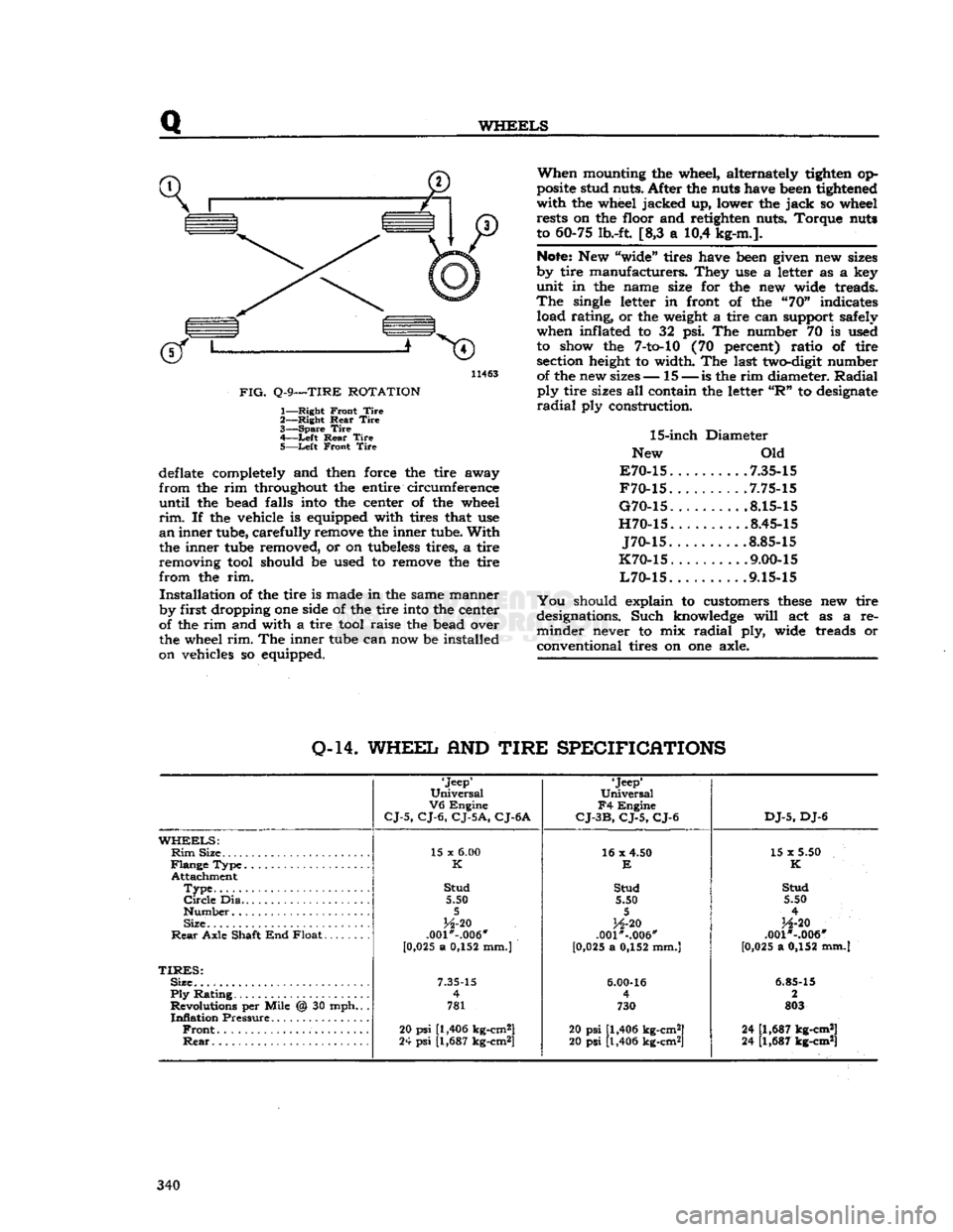
help tires, and wears out shock absorbers. Rotate the tires as shown in Fig. Q-9 for correct
rotation system.
Q-13.
Tire
Removal
and
Installation
To
remove a tire from a drop center rim, first
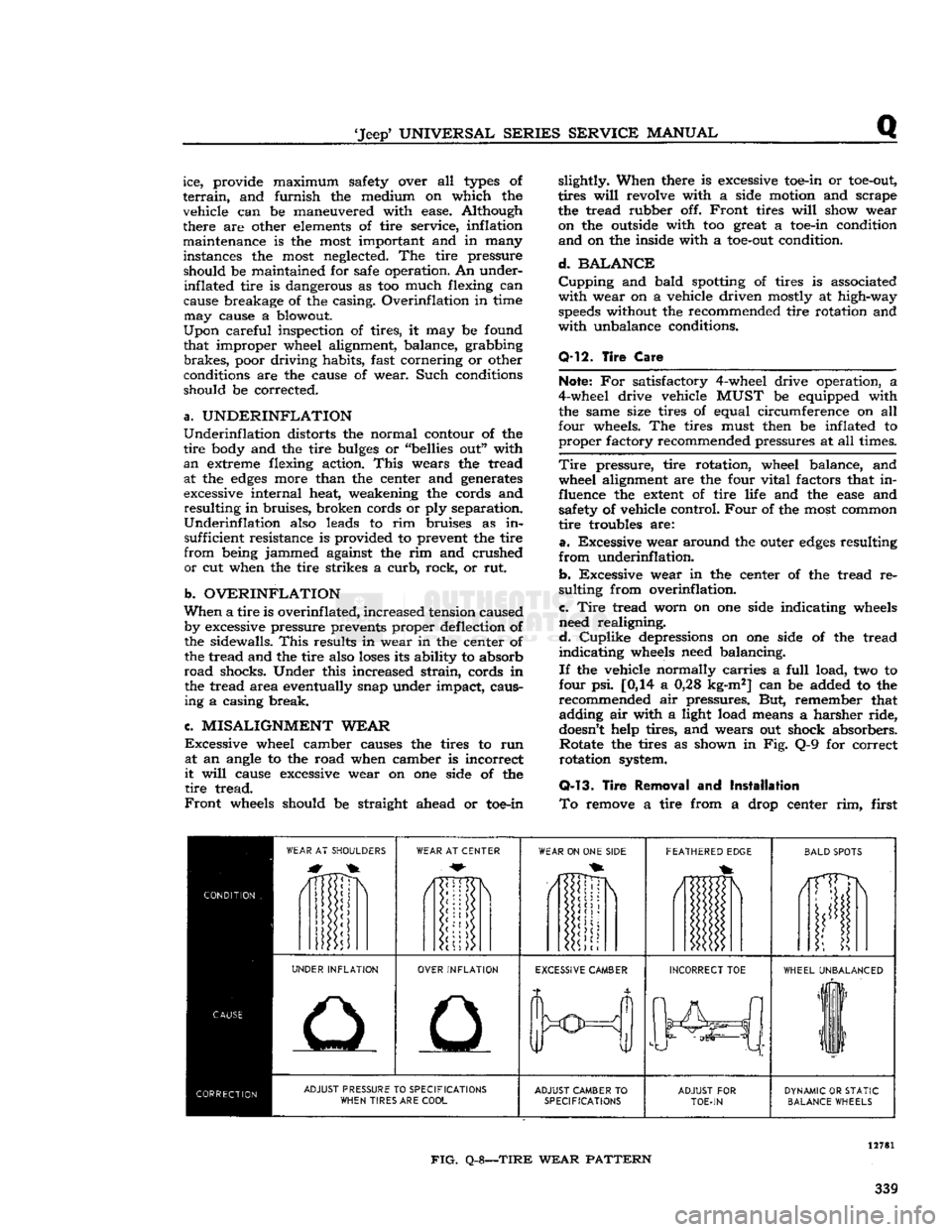
WEAR
AT SHOULDERS
WEAR
AT CENTER
WEAR
ON ONE
SIDE
FEATHERED
EDGE
BALD
SPOTS
/1TTDN
i
UNDER
INFLATION
OVER
INFLATION
EXCESSIVE
CAMBER
INCORRECT
TOE
WHEEL
UNBALANCED
liF
11
ADJUST
PRESSURE TO
SPECIFICATIONS
WHEN
TIRES ARE
COOL
ADJUST
CAMBER
TO
SPECIFICATIONS
ADJUST
FOR
TOE-IN
DYNAMIC
OR
STATIC
BALANCE
WHEELS
FIG.
Q-8—TIRE
WEAR
PATTERN
339
Page 340 of 376

Q
WHEELS
11463
FIG.
Q-9—TIRE
ROTATION
1—
Right
Front
Tire
2—
Right
Rear
Tire
3—
Spare
Tire
4—
-Left
Rear
Tire
5—
Left
Front
Tire
deflate completely and then force the tire away
from
the rim throughout the entire circumference
until
the bead falls into the center of the wheel
rim.
If the vehicle is equipped with tires that use
an
inner tube, carefully remove the inner tube.
With
the inner tube removed, or on tubeless tires, a tire
removing tool should be used to remove the tire
from
the rim.
Installation
of the tire is made in the same manner
by first dropping one side of the tire into the center
of the rim and with a tire tool raise the bead over
the wheel
rim.
The inner tube can now be installed
on vehicles so equipped.
When
mounting the wheel, alternately tighten op
posite stud nuts. After the nuts have been tightened
with
the wheel jacked up, lower the
jack
so wheel rests on the floor and retighten nuts. Torque nuts
to 60-75 lb.-ft. [8,3 a 10,4 kg-m.].
Note:
New "wide" tires have been given new sizes
by tire manufacturers. They use a letter as a key
unit
in the name size for the new wide treads.
The
single letter in front of the "70" indicates load rating, or the weight a tire can support safely
when inflated to 32 psi. The number 70 is used to show the
7-to-10
(70 percent) ratio of tire section height to width. The last two-digit number of the new sizes— 15 —
is
the rim diameter.
Radial
ply
tire sizes all contain the letter
"R"
to designate
radial
ply construction.
15-inch
Diameter
New Old
E70-15
7.35-15
F70-15
.7.75-15
G70-15
8.15-15
H70-15
8.45-15
J70-15
.8.85-15
K70-15
. .... .9.00-15
L70-15
9.15-15
You
should explain to customers
these
new tire
designations. Such knowledge
will
act as a re
minder
never to mix
radial
ply, wide treads or
conventional tires on one axle.
0-14.
WHEEL
AND
TIRE
SPECIFICATIONS
'Jeep'
Universal
V6
Engine
CJ-5,
CJ-6,
CJ-5A,
CJ-6A
'Jeep*
Universal
F4
Engine
CJ-3B,
CJ-5,
CJ-6
DJ-5,
DJ-6
WHEELS:
Rim
Size 15 x
6.00
16 x 4.50
15 x 5.50
K
E
K
Attachment
Type
Stud
Stud Stud
Circle
Dia 5.50 5.50 5.50
5 5
4
Size
H-20
H-20
H-20
Rear
Axle Shaft End Float .001*-.006"
.001"-.006" .001 *-.006"
[0 ,025 a 0,152 mm.)
[0,025 a 0,152 mm.] [0,025 a 0,152 mm.]
TIRES:
Size.
7.35-15
6.00-16
6.85-15
Ply
Rating 4
4 2
Revolutions per Mile @ 30 mph.. . 781 730 803
Inflation
Pressure
Front
20
psi
[1,406 kg-cm2]
20 psi [1,406 kg-cm2] 24 [1,687 kg-cm*]
Rear
24
psi
[1,687 kg-cm*]
20 psi [1,406 kg-cm2] 24 [1,687 kg-cm*] 340
Page 360 of 376

u
MISCELLANEOUS
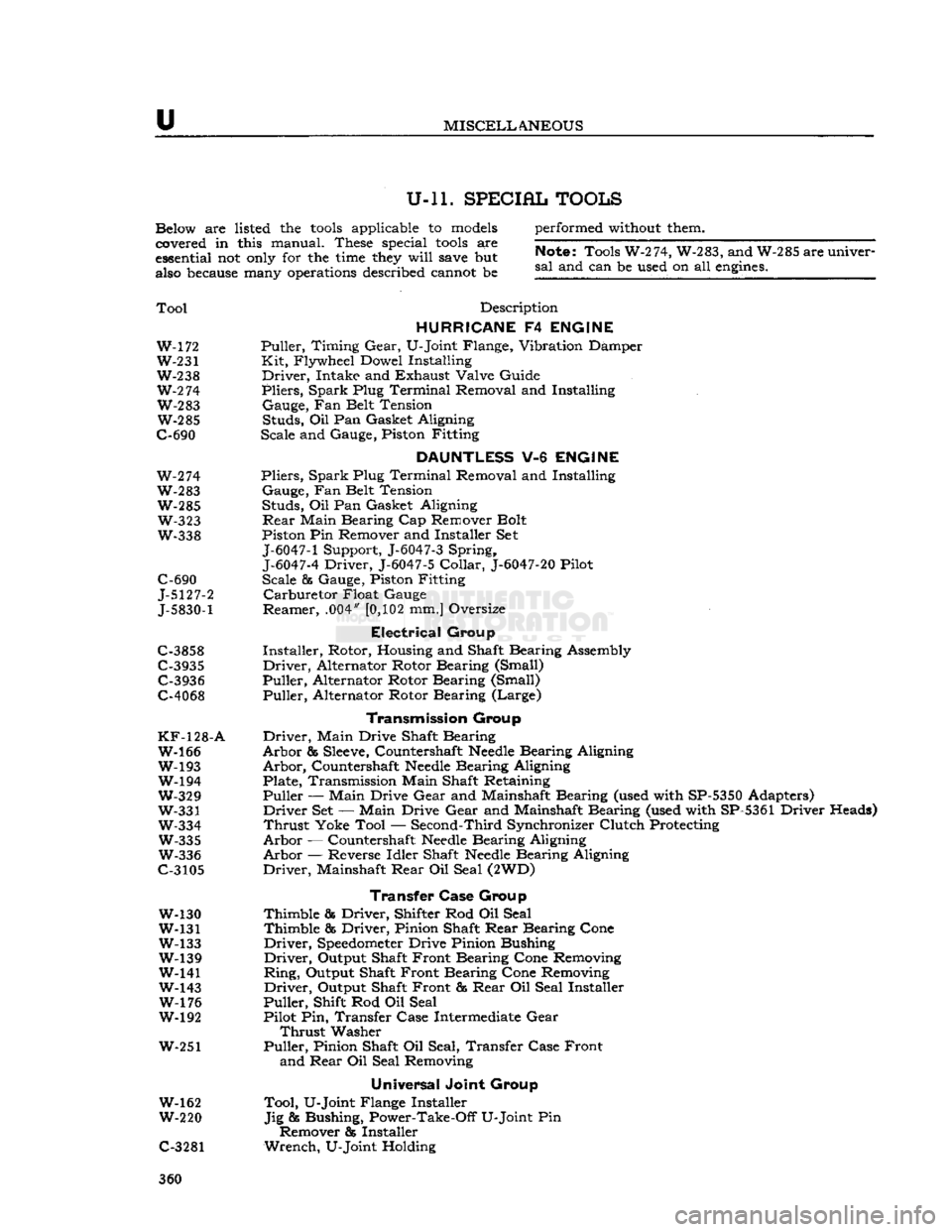
U-ll. SPECIAL TOOLS
Below are listed the
tools
applicable to
models
covered in this manual. These special
tools
are
essential not
only
for the
time
they
will
save
but
also
because
many
operations
described cannot be performed
without
them.
Note;
Tools W-274, W-283, and W-285 are univer
sal
and can be used on all
engines.
Tool
Description
HURRICANE
F4
ENGINE
W-172 Puller, Timing
Gear,
U-Joint Flange, Vibration Damper W-231 Kit, Flywheel Dowel Installing
W-238 Driver, Intake and Exhaust Valve Guide
W-2
74 Pliers, Spark Plug Terminal Removal and Installing W-283 Gauge, Fan Belt Tension W-285 Studs, Oil Pan Gasket Aligning
C-690 Scale and Gauge, Piston Fitting
DAUNTLESS
V-6
ENGINE
W-274 Pliers, Spark Plug Terminal Removal and Installing
W-283 Gauge, Fan Belt Tension W-285 Studs, Oil Pan Gasket Aligning W-323
Rear
Main Bearing Cap Remover Bolt
W-338 Piston Pin Remover and Installer Set
J-6047-1
Support, J-6047-3 Spring,
J-6047-4
Driver, J-6047-5
Collar,
J-6047-20
Pilot
C-690 Scale & Gauge, Piston Fitting
J-5127-2 Carburetor Float Gauge
J-5830-1
Reamer, .004"
[0,102
mm.] Oversize
Electrical
Group
C-3858 Installer, Rotor, Housing and Shaft Bearing Assembly
C-3935 Driver, Alternator Rotor Bearing (Small) C-3936 Puller, Alternator Rotor Bearing (Small)
C-4068 Puller, Alternator Rotor Bearing (Large)
Transmission
Group
KF-128-A
Driver, Main Drive Shaft Bearing W-166 Arbor &
Sleeve,
Countershaft
Needle
Bearing Aligning
W-193 Arbor, Countershaft
Needle
Bearing Aligning W-194 Plate, Transmission Main Shaft Retaining
W-329 Puller — Main Drive
Gear
and Mainshaft Bearing (used with SP-5350 Adapters)
W-331 Driver Set — Main Drive
Gear
and Mainshaft Bearing (used with SP-5361 Driver Heads)
W-334 Thrust Yoke Tool — Second-Third Synchronizer Clutch Protecting W-335 Arbor — Countershaft
Needle
Bearing Aligning
W-336 Arbor — Reverse Idler Shaft
Needle
Bearing Aligning
C-3105 Driver, Mainshaft
Rear
Oil Seal (2WD)
Transfer Case
Group
W-130 Thimble & Driver, Shifter Rod Oil Seal
W-131 Thimble & Driver, Pinion Shaft
Rear
Bearing Cone
W-133 Driver,
Speedometer
Drive Pinion Bushing W-139 Driver, Output Shaft Front Bearing Cone Removing
W-141 Ring, Output Shaft Front Bearing Cone Removing
W-143 Driver, Output Shaft Front &
Rear
Oil Seal Installer W-176 Puller, Shift Rod Oil Seal
W-192 Pilot Pin, Transfer Case Intermediate
Gear
Thrust
Washer
W-251 Puller, Pinion Shaft Oil Seal, Transfer Case Front and
Rear
Oil Seal Removing
Universal
Joint Group
W-162 Tool, U-Joint Flange Installer
W-220 Jig & Bushing, Power-Take-Off U-Joint Pin Remover & Installer
C-3281 Wrench, U-Joint Holding 360
Page 364 of 376

u
MISCELLANEOUS
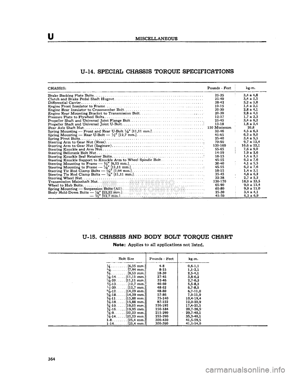
U-14.
SPECIAL
CHASSIS
TORQUE
SPECIFICATIONS
CHASSIS:
Pounds
-
Feet
j kg-m.
Brake
Backing Plate Bolts.
25-35 ! 3,4 a 4,8
Clutch
and
Brake Pedal Shaft Hugnut
25-40 3,4 a 5,5
Differential
Carrier
38-42 5,2 a 5,8
Engine
Front Insulator
to
Frame.
10-15 1,4 a 2,1
Engine
Rear
Insulator
to
Crossmember Bolt.
. . ... 20-30 2,8 a 4,1
Engine
Rear
Mounting Bracket
to
Transmission Bolt.
20-30 2,8 a 4,1
Pressure
Plate
to
Flywheel Bolts
12-17 1,7 a 2,3
Propeller Shaft
and
Universal Joint Flange Bolt
25-45 3,4 a 6,2
Propeller Shaft
and
Universal Joint U-Bolt
1 13-18 : 1,8 a 2,4
Rear
Axle Shaft
Nut 150
Minimum
; 20,8
Spring
Mounting
—
Front
and
Rear
U-Bolt
V^n [11,11 mm.] 32-46 i 4,5 a 6,3
Spring
Mounting —-
Rear
U-Bolt
— [12,7 mm.] 45-65 6,2 a 9,0
Spring
Pivot Bolts
." 25-40 3,4 a 5,5
Steering Arm
to
Gear
Nut
(Ross)
..
i
70-90 9,7 a 12,4
Steering Arm
to
Gear
Nut
(Saginaw)
' 120-160 16,6 a 22,1
Steering Knuckle
and
Arm Nut..........
55-65 j 7,6 a 9,0
Steering Bellcrank Bolt
Nut 14-19 < 1,9 a 2,6
Steering Knuckle Seal Retainer Bolts
S 10-15 1,4 a 2,1
Steering Knuckle Support
to
Knuckle Arm
to
Wheel Spindle Bolt
45-55 , 6,2 a 7,6
Steering Mounting
to
Frame
—
Y%
[9,53 mm.] 30-40 '• 4,1 a 5,5
Steering Mounting
to
Frame
— W [11,11
mm.]...
i 45-55 6,2 a 7,6
Steering
Tie Rod
Clamp Bolts
— [7,94 mm.] 10-15 1,4 a 2,1
Steering
Tie Rod
Clamp Bolts
— Ke" [U,H mm.] ; 35-45 , 4,8 a 6,2
Steering Wheel
Nut 32-38 1 2,7 a 5,2
Transmission
Mainshaft
Nut 130-170 18,0 a 23,5
Wheel
to Hub
Bolts
65-90 9,0 a 12,4
Spring
Mounting
—
Suspension Bolts
(All) , 65-80 9,0 a 11,0
Body Hold-Down Bolts
— W [11,11 mm.} 25-30 i 3,4 a 4,1
—
W [12,7 mm.l , . . 45-50 I 6,2 a 6,9
U-15.
CHASSIS
AND
BODY
BOLT
TORQUE
CHART
Note:
Applies to all applications not listed.
Bolt Size Pounds
-
Feet
kg-m.
.....
[6,35 mm.] 4-8
0,6-1,1
[7,94 mm.] 8-15
1,1-2,1
[9,53 mm.] 18-30
2,5-4,1
"Mrl4.
[11,11 mm.]
27-45
3,8-6,2
116-20. [11,11 mm.] 32-46
2,7-6,3
M-13.
[12,7
mm.]
40-60
5,5-8,3
H-20
[12,7
mm.]
48-62
6,7-8,5
%-12.
[14,29 mm.]
48-80
6,7-11,0
%-lB.
[14,29 mm.]
57-86
7,9-11,9
5A-n. [15,88 mm.]
75-140
10,4-19,4
[15,88 mm.] 87-152
12,0-20,9
U-io.
[19,05 mm.]
126-192
17,4-25,5
§4-16.
[19,05 mm.]
150-184
20,7-26,5
Vs'9..
[22,23 mm.]
215-290
29,7-40,1
K-14.
[22,23 mm.]
255-290
35,3-40,1
1-8 [25,4 mm.] 300-430
41,5-59,5
1-14. . [25,4 mm.]
300-390 41,5-54,0 364