water pump JEEP CJ 1953 Owner's Manual
[x] Cancel search | Manufacturer: JEEP, Model Year: 1953, Model line: CJ, Model: JEEP CJ 1953Pages: 376, PDF Size: 19.96 MB
Page 78 of 376
01
DAUNTLESS
V-6
ENGINE
14358
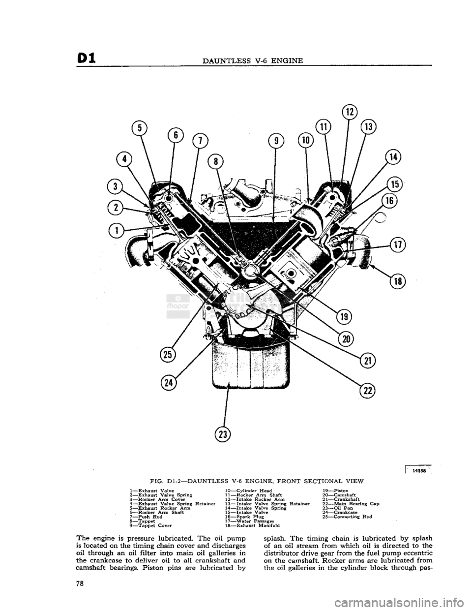
FIG.
Dl-2—DAUNTLESS
V-6
ENGINE, FRONT SECTIONAL VIEW
1—
Exhaust
Valve
2—
Exhaust
Valve Spring
3—
Rocker
Arm Cover
4—
—Exhaust
Valve Spring Retainer 5—
Exhaust
Rocker Arm
6—
Rocker
Arm Shaft 7— push Rod
8— Tappet
9— Tappet Cover 10—
Cylinder
Head
11—
Rocker
Arm Shaft
12—
Intake
Rocker Arm
13—
Intake
Valve Spring Retainer
14—
Intake
Valve Spring
15—
Intake
Valve 16—
Spark
Plug
17—
Water
Passages 18—
Exhaust
Manifold 19— Piston
20—
Camshaft
21—
Crankshaft
22—
Main
Bearing Cap
23—
Oil
Pan
24—
Crankcase
25— Connecting Rod
The
engine
is pressure lubricated. The oil pump
is located on the timing chain cover and discharges
oil
through an oil filter
into
main oil galleries in
the crankcase to deliver oil to all crankshaft and
camshaft bearings. Piston pins are lubricated by- splash. The timing chain is lubricated by splash
of an oil stream from which oil is directed to the
distributor drive gear from the fuel pump eccentric
on the camshaft. Rocker arms are lubricated from
the oil galleries in the cylinder block through pas- 78
Page 79 of 376
'Jeep*
UNIVERSAL SERIES SERVICE
MANUAL
Dl
12710
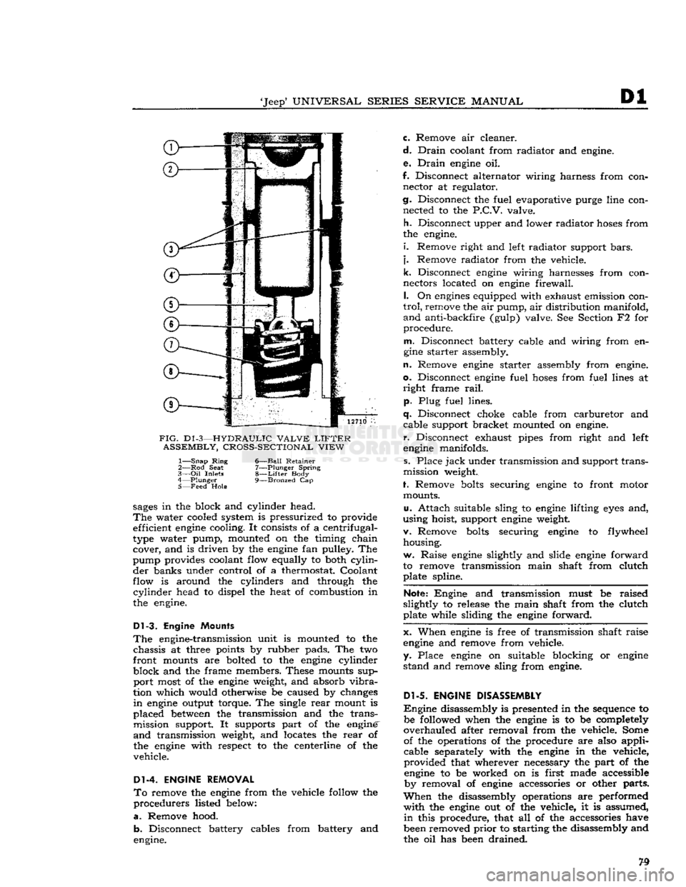
FIG.
D1
-3—HYDRAULIC VALVE
LIFTER
ASSEMBLY, CROSS-SECTIONAL VIEW
1—
Snap
Ring
6—Ball Retainer
2— Rod
Seat
7—Plunger Spring
3—
Oil
Inlets
8—Lifter
Body
4—
Plunger
9—Bronzed
Cap
5— Feed
Hole
sages
in the block and cylinder head.
The
water cooled system is pressurized to provide efficient
engine
cooling. It consists of a centrifugal-
type water pump, mounted on the timing chain cover, and is driven by the
engine
fan pulley. The
pump provides coolant flow equally to both
cylin
der banks under control of a thermostat. Coolant
flow is around the cylinders and through the
cylinder
head to dispel the heat of combustion in
the engine.
Dl-3.
Engine Mounts
The
engine-transmission unit is mounted to the chassis at three points by rubber pads. The two
front mounts are bolted to the
engine
cylinder
block and the frame members. These mounts sup port most of the
engine
weight, and absorb
vibra
tion which would otherwise be caused by changes
in
engine
output torque. The single
rear
mount is
placed
between
the transmission and the trans mission support. It supports part of the engine'
and
transmission weight, and locates the
rear
of
the
engine
with respect to the centerline of the
vehicle.
Dl-4. ENGINE REMOVAL
To
remove the
engine
from the vehicle follow the
procedurers listed below:
a.
Remove hood. b. Disconnect battery cables from battery and
engine. c. Remove air cleaner.
d.
Drain
coolant from radiator and engine.
e.
Drain
engine
oil.
f. Disconnect alternator wiring harness from con nector at regulator.
cj.
Disconnect the fuel evaporative purge line con nected to the
P.C.V.
valve.
h.
Disconnect upper and lower radiator
hoses
from
the engine.
i.
Remove right and left radiator support
bars,
j.
Remove radiator from the vehicle.
k.
Disconnect
engine
wiring harnesses from con
nectors located on
engine
firewall.
I.
On
engines
equipped with exhaust emission con
trol,
remove the air pump, air distribution manifold,
and
anti-backfire (gulp) valve. See Section F2 for
procedure.
m.
Disconnect battery cable and wiring from en
gine
starter assembly.
n.
Remove
engine
starter assembly from engine,
o.
Disconnect
engine
fuel
hoses
from fuel lines at
right
frame
rail,
p. Plug fuel lines.
q.
Disconnect choke cable from carburetor and cable support bracket mounted on engine,
r.
Disconnect exhaust pipes from right and left
engine
manifolds.
s. Place
jack
under transmission and support trans
mission weight.
f. Remove
bolts
securing
engine
to front motor mounts.
u.
Attach suitable sling to
engine
lifting
eyes
and,
using hoist, support
engine
weight.
v. Remove
bolts
securing
engine
to flywheel housing.
w. Raise
engine
slightly and slide
engine
forward
to remove transmission main shaft from clutch plate spline.
Note:
Engine and transmission must be raised
slightly to release the main shaft from the clutch
plate while sliding the
engine
forward.
x. When
engine
is free of transmission shaft raise
engine
and remove from vehicle,
y. Place
engine
on suitable blocking or
engine
stand and remove sling from engine.
Dl-5.
ENGINE DISASSEMBLY
Engine
disassembly is presented in the sequence to be followed when the
engine
is to be completely
overhauled after removal from the vehicle. Some of the operations of the procedure are also applicable separately with the
engine
in the vehicle,
provided that wherever necessary the part of the
engine
to be worked on is first made accessible by removal of
engine
accessories or other parts.
When
the disassembly operations are performed
with
the
engine
out of the vehicle, it is assumed,
in
this procedure, that all of the accessories have
been removed
prior
to starting the disassembly and
the oil has been drained.
Page 80 of 376
Dl
DAUNTLESS
V-6
ENGINE
In
addition to the instructions covering operations
for disassembling the
engine
out of the vehicle, special instructions are given to cover different
operations required when disassembly is
done
with
the
engine
installed.
During
disassembly operations, the
engine
should be mounted in a suitable
engine
repair stand.
Where
practicable, modify or adapt an existing re
pair
stand as necessary to accommodate the
engine.
If
an
engine
repair stand is not used, take care to
perform
disassembly operations in a manner that
will
protect personnel against an accident and the
engine
and its parts against damage.
Dl-6.
Mounting Engine
On
Engine Stand
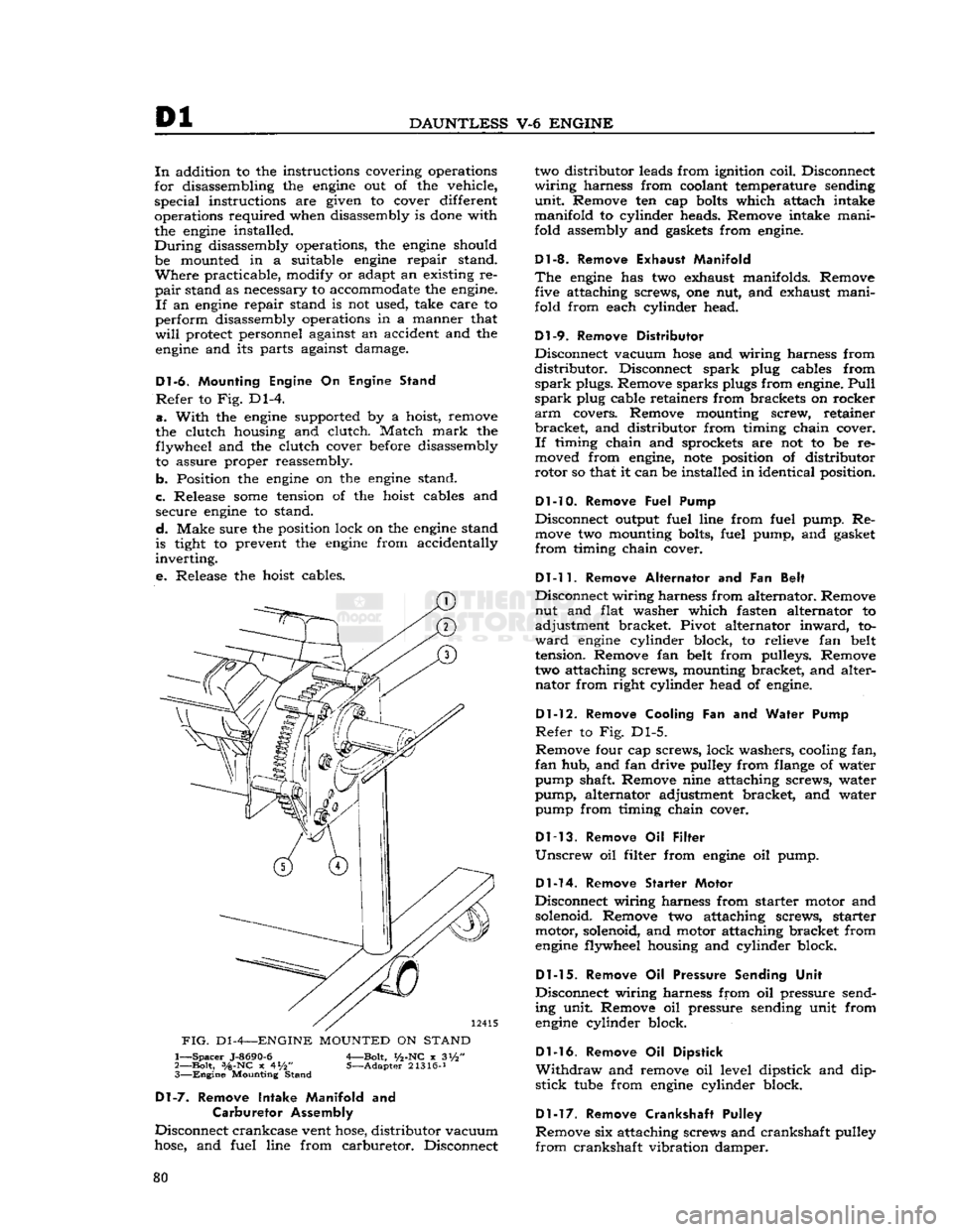
Refer
to Fig. Dl-4.
a.
With
the
engine
supported by a hoist, remove
the clutch housing and clutch. Match
mark
the flywheel and the clutch cover before disassembly to assure proper reassembly.
b. Position the
engine
on the
engine
stand.
c. Release
some
tension of the hoist cables and secure
engine
to stand.
d.
Make sure the position lock on the
engine
stand
is tight to prevent the
engine
from accidentally
inverting.
e.
Release the hoist cables.
FIG.
D1
-4—ENGINE
MOUNTED
ON
STAND
1—
Spacer
J-8690-6
A—Bolt,
i/2-NC
x 3i/2"
2—
Bolt,
3/a-NC
x 4*/2" 5—Adapter 21316-J 3—
Engine
Mounting Stand
Dl-7.
Remove Intake Manifold
and
Carburetor Assembly
Disconnect crankcase vent
hose,
distributor vacuum
hose,
and fuel line from carburetor. Disconnect two distributor leads from ignition coil. Disconnect
wiring
harness from coolant temperature sending
unit.
Remove ten cap
bolts
which attach intake
manifold to cylinder heads. Remove intake mani
fold assembly and gaskets from
engine.
Dl-8. Remove Exhaust Manifold
The
engine
has two exhaust manifolds. Remove five attaching screws, one nut, and exhaust mani
fold from each cylinder head.
Dl-9.
Remove Distributor
Disconnect vacuum
hose
and wiring harness from
distributor.
Disconnect spark plug cables from
spark
plugs. Remove sparks plugs from
engine.
Pull
spark
plug cable retainers from brackets on rocker
arm
covers. Remove mounting screw, retainer
bracket,
and distributor from timing chain cover.
If
timing chain and sprockets are not to be re
moved from
engine,
note
position of distributor
rotor so that it can be installed in identical position.
Dl-10. Remove
Fuel Pump
Disconnect output fuel line from fuel pump. Re
move
two mounting bolts, fuel pump, and gasket
from
timing chain cover.
Dl-11.
Remove Alternator
and Fan
Belt
Disconnect wiring harness from alternator. Remove nut and flat washer which fasten alternator to
adjustment bracket. Pivot alternator
inward,
to
ward
engine
cylinder block, to relieve fan belt
tension. Remove fan belt from pulleys. Remove
two attaching screws, mounting bracket, and alter nator from right cylinder head of
engine.
Dl-12.
Remove Cooling
Fan and
Water Pump
Refer
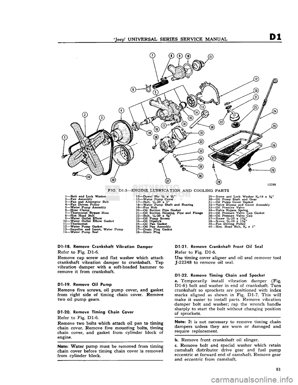
to Fig. Dl-5.
Remove four cap screws, lock washers, cooling fan,
fan
hub, and fan drive pulley from flange of water
pump shaft. Remove nine attaching screws, water
pump, alternator adjustment bracket, and water pump from timing chain cover.
Dl-13.
Remove
Oil
Filter
Unscrew
oil filter from
engine
oil pump.
Dl-14.
Remove Starter Motor
Disconnect wiring harness from starter motor and
solenoid. Remove two attaching screws, starter motor, solenoid, and motor attaching bracket from
engine
flywheel housing and cylinder block.
Dl-15.
Remove
Oil
Pressure Sending Unit
Disconnect wiring harness from oil pressure send
ing unit. Remove oil pressure sending unit from
engine
cylinder block.
Dl-16.
Remove
Oil
Dipstick
Withdraw
and remove oil level dipstick and dip
stick
tube
from
engine
cylinder block.
Dl-17.
Remove Crankshaft Pulley
Remove six attaching screws and crankshaft pulley
from
crankshaft vibration damper. 80
Page 81 of 376
'Jeep'
UNIVERSAL
SERIES
SERVICE
MANUAL
Dl
13296
FIG.
Dl-5—ENGINE
LUBRICATION
AND
COOLING
PARTS
1— Bolt and
Lock
Washer
2—
Fan
Assembly
3—
Fan
and Alternator Belt
4—
Fan
Driven Pulley 5— Water Pump Assembly
6—
Hose
Clamp 7— Thermostat Bypass
Hose
8—Hex
Head Bolt
9— Water Outlet Elbow
10— Water Outlet Elbow Gasket
11— Thermostat
12— Water Pump Gasket
13— Impeller and Insert, Water Pump
14— Water Pump Seal 15— Dowel Pin % x Vfc"
16— Water Pump Cover
17— Bolt,
1/4-20
x 1"
18— Water Pump Shaft and Bearing
19—
Fan
Hub
20—
-Oil
Suction Pipe Gasket
21—
Oil
Suction Housing, Pipe and Flange
22— Bolt,
y4-20
x s/8"
23—
Oil
Pump Screen
24—
Oil
Dipstick
25—
Oil
Pan Gasket
26—
Oil
Pan Assembly
27—
Drain
Plug Gasket
28—
Drain
Plug 29— Screw and
Lock
Washer #6-18 x %
30—
Oil
Pump Shaft and Gear
31—
Oil
Pump Cover Gasket
32— Valve Bypass and Cover Assembly
33—
Oil
Pressure Valve 34— Valve Bypass Spring
35—
Oil
Pressure Valve Cap Gasket
36—
Oil
Pressure Valve Cap
37— Screw V4-20 x lVg"
38— Screw 1/4-20 x 1W' 39—
Fan
Driving Pulley
40— Hex. Head Bolt, x 1"
Dl-13.
Remove
Crankshaft
Vibration Damper
Refer
to Fig. Dl-6.
Remove cap screw and flat washer which attach
crankshaft
vibration damper to crankshaft. Tap
vibration
damper with a soft-headed hammer to remove it from crankshaft.
Dl-19.
Remove Oil Pump
Remove five screws, oil pump cover, and gasket
from
right side of timing chain cover. Remove
two oil pump gears.
D1-20.
Remove Timing Chain Cover
Refer
to Fig. Dl-6. Remove two
bolts
which attach oil pan to timing
chain
cover. Remove five mounting bolts, timing
chain
cover, and gasket from cylinder block of
engine.
Note:
Water pump must be removed from timing
chain
cover before timing chain cover is removed
from
cylinder block.
Dl-21.
Remove Crankshaft Front
Oil
Seal
Refer
to Fig. Dl-6.
Use timing cover aligner and oil seal remover
tool
J-22248 to remove oil seal.
Dl-22.
Remove Timing Chain
and
Spocket
a.
Temporarily install vibration damper (Fig.
Dl-6)
bolt and washer in end of crankshaft.
Turn
crankshaft
so sprockets are positioned with index
marks
aligned as shown in Fig. Dl-7.
This
will
make it easier to install parts. Remove vibration
damper bolt and washer; rap the wrench handle
sharply
to start the bolt without changing position
of sprockets.
Note:
It is not necessary to remove timing chain
dampers unless they are worn or damaged and
require
replacement.
b. Remove front crankshaft oil slinger.
c. Remove bolt and special washer which retain
camshaft distributor drive gear and fuel pump
eccentric at forward end of camshaft. Remove gear
and
eccentric from camshaft. 81
Page 95 of 376
'Jeep*
UNIVERSAL
SERIES
SERVICE
MANUAL
Dl
Dl-65.
Rocker Arm Cover Cleaning
and Inspection
a.
Clean
both rocker arm covers with suitable
cleaning solvent and dry thoroughly.
b.
Inspect each rocker arm cover visually for
scratches,
bends, dents, and tears. Replace cover
if
unserviceable.
Dl-66.
Timing Chain
and
Sprocket Inspection
Inspect
the timing chain and both sprockets for
damage or excessive wear. Replace unserviceable
parts.
Dl-67.
Timing Chain Cover Cleaning and Inspection
a.
Clean
the timing chain cover with suitable clean
ing solvent and dry with compressed air.
b.
Inspect the cover visually for breaks,
cracks,
and
other damage.
With
a straightedge, check cylinder
block, water pump, and oil pump faces for bends
and
distortion.
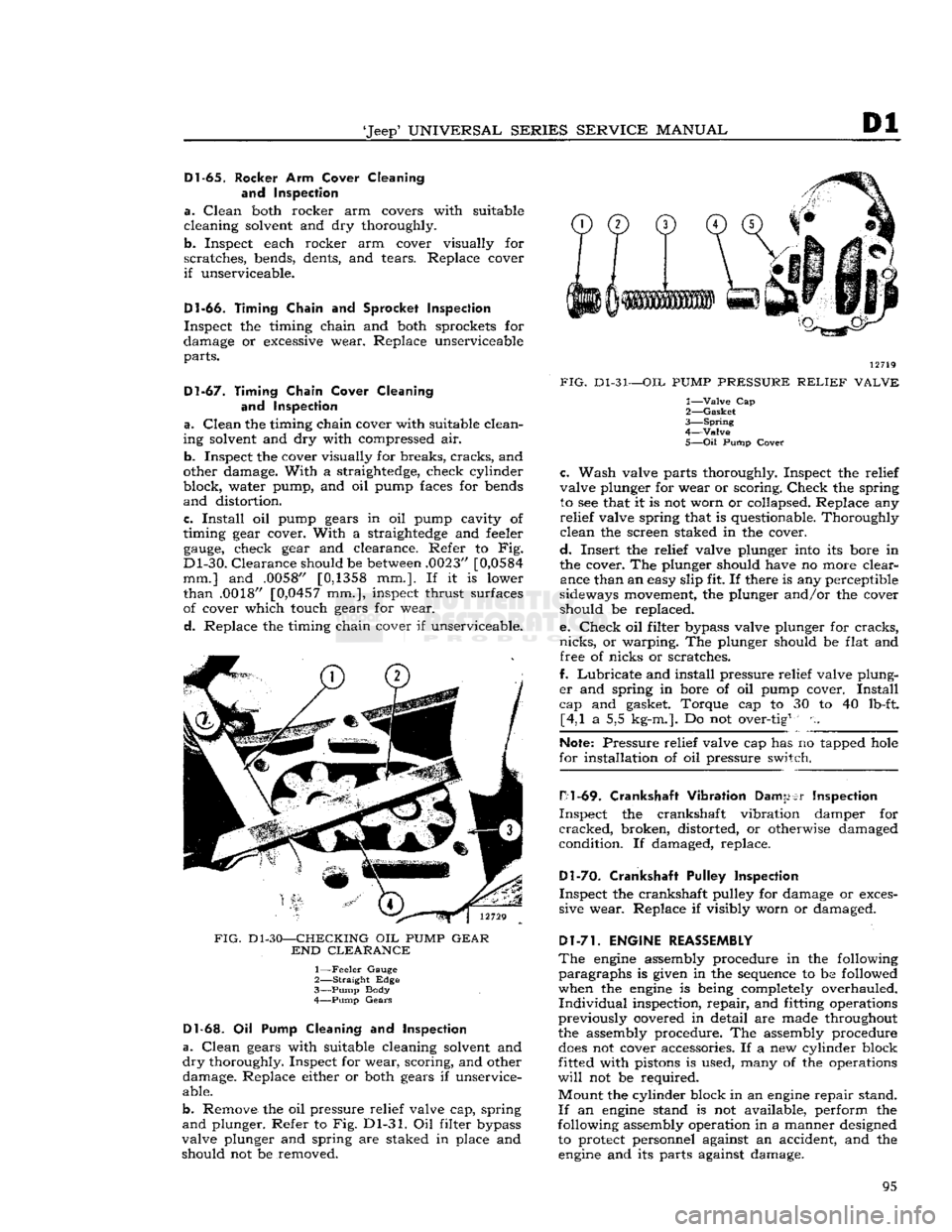
c.
Install
oil pump gears in oil pump cavity of
timing gear cover.
With
a straightedge and feeler
gauge,
check gear and clearance. Refer to Fig.
Dl-30.
Clearance
should be
between
.0023"
[0,0584
mm.] and .0058"
[0,1358
mm.]. If it is lower
than
.0018" [0,0457 mm.], inspect thrust surfaces
of cover which touch gears for wear.
d.
Replace the timing chain cover if unserviceable.
FIG.
Dl-30—CHECKING
OIL
PUMP
GEAR
END
CLEARANCE
1—
Feeler
Gauge
2—
Straight
Edge
3—
Pump
Body
4—
Pump
Gears
Dl-63.
Oil Pump Cleaning and
Inspection
a.
Clean
gears with suitable cleaning solvent and
dry
thoroughly. Inspect for wear, scoring, and other damage. Replace either or both gears if unservice
able.
b.
Remove the oil pressure relief valve cap, spring
and
plunger. Refer to Fig. Dl-31. Oil filter bypass
valve plunger and spring are staked in place and should not be removed. 12719
FIG.
Dl-31—OIL
PUMP
PRESSURE
RELIEF
VALVE
1—
Valve
Cap
2—
Gasket
3—
Spring
4—Valve
5—
Oil
Pump
Cover
c.
Wash valve parts thoroughly. Inspect the relief
valve plunger for wear or scoring.
Check
the spring to see that it is not worn or collapsed. Replace any
relief
valve spring that is questionable. Thoroughly
clean
the screen staked in the cover.
d.
Insert the relief valve plunger into its bore in
the cover. The plunger should have no more clear ance than an easy slip fit. If there is any perceptible
sideways movement, the plunger and/or the cover should be replaced.
e.
Check
oil filter bypass valve plunger for
cracks,
nicks,
or warping. The plunger should be flat and free of nicks or scratches.
f.
Lubricate
and install pressure relief valve plung
er
and spring in bore of oil pump cover.
Install
cap and gasket. Torque cap to 30 to 40 lb-ft. [4,1 a 5,5 kg-m.]. Do not over-tig1 n.
Note:
Pressure relief valve cap has no tapped
hole
for installation of oil pressure switch.
H1
-69.
Crankshaft Vibration
Damper
Inspection
Inspect
the crankshaft vibration damper for
cracked,
broken, distorted, or otherwise damaged
condition. If damaged, replace.
Dl-70.
Crankshaft Pulley Inspection
Inspect
the crankshaft pulley for damage or exces
sive wear. Replace if visibly worn or damaged.
Dl-71.
ENGINE REASSEMBLY
The
engine
assembly procedure in the following
paragraphs
is given in the sequence to be followed
when the
engine
is being completely overhauled.
Individual
inspection,
repair,
and fitting operations
previously covered in detail are made throughout
the assembly procedure. The assembly procedure
does
not cover accessories. If a new cylinder block
fitted with pistons is used, many of the operations
will
not be required.
Mount
the cylinder block in an
engine
repair stand.
If
an
engine
stand is not available, perform the
following assembly operation in a manner designed to protect personnel against an accident, and the
engine
and its parts against damage. 95
Page 96 of 376
Dl
DAUNTLESS
V-6
ENGINE
Note:
During
engine
reassembly, use Perfect Seal
Aerosol
Spray Sealer
Part
No.
994757
on all en
gine
gaskets to ensure against vacuum, oil, gasoline
and
water leaks. Apply to head gaskets, valve covers, water pumps, oil pan gaskets, radiator and
heater
hose
connections, felt gaskets, gasoline and
oil
line connections, stud bolts, spark plug threads,
and
grease retainer washers. Refer to manufac
turer's
instructions on container for proper appli
cation procedure.
Dl-72.
Cylinder
Block
and Crankshaft
Rear
Oil Seals
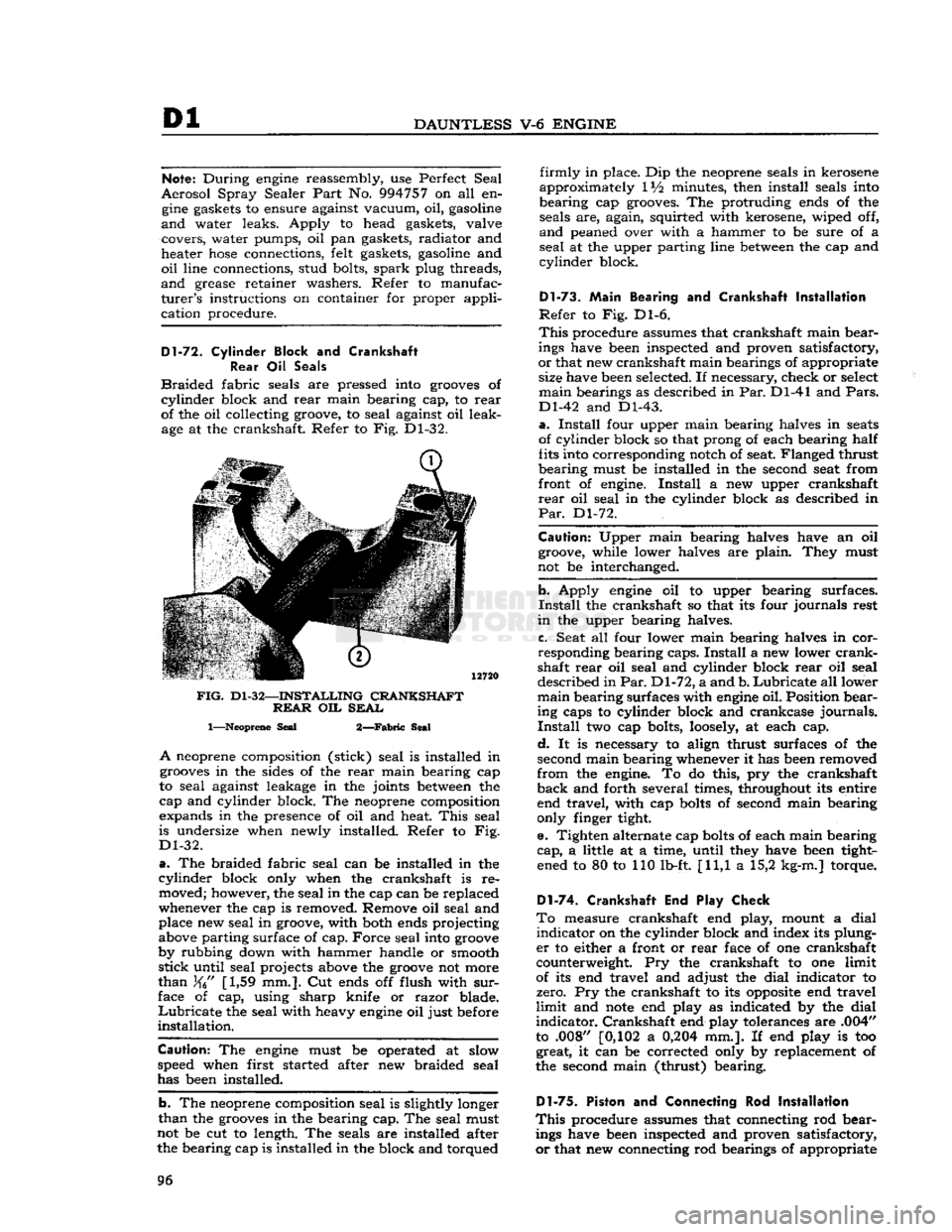
Braided
fabric seals are pressed into
grooves
of
cylinder
block and
rear
main bearing cap, to
rear
of the oil collecting groove, to seal against oil leak age at the crankshaft. Refer to Fig. Dl-32.
FIG.
Dl-32—INSTALLING
CRANKSHAFT REAR
OIL
SEAL
1—Neoprene
Seal
2—Fabric
Seal
A
neoprene composition (stick) seal is installed in
grooves
in the sides of the
rear
main bearing cap
to seal against leakage in the joints
between
the
cap and cylinder block. The neoprene composition
expands in the presence of oil and heat.
This
seal
is undersize when newly installed. Refer to Fig.
Dl-32.
a.
The braided fabric seal can be installed in the
cylinder
block only when the crankshaft is re moved; however, the seal in the cap can be replaced
whenever the cap is removed. Remove oil seal and place new seal in groove, with both ends projecting
above parting surface of cap. Force seal into
groove
by rubbing down with hammer handle or smooth
stick
until seal projects above the
groove
not more
than
[1,59 mm.]. Cut ends off flush with
sur
face of cap, using sharp knife or razor blade.
Lubricate
the seal with heavy
engine
oil just before
installation.
Caution:
The
engine
must be operated at slow
speed when first started after new braided seal
has been installed.
b. The neoprene composition seal is slightly longer
than
the
grooves
in the bearing cap. The seal must
not be cut to length. The seals are installed after the bearing cap is installed in the block and torqued
firmly
in place. Dip the neoprene seals in kerosene
approximately IV2 minutes, then install seals into
bearing cap grooves. The protruding ends of the seals are, again, squirted with kerosene, wiped off,
and
peaned over with a hammer to be sure of a
seal
at the upper parting line
between
the cap and
cylinder
block.
Dl-73.
Main
Bearing and Crankshaft
Installation
Refer
to Fig. Dl-6.
This
procedure assumes that crankshaft main bear
ings have been inspected and proven satisfactory,
or
that new crankshaft main bearings of appropriate size have been selected. If necessary, check or select
main
bearings as described in Par. Dl-41 and
Pars.
Dl-42 and Dl-43.
a.
Install
four upper main bearing halves in
seats
of cylinder block so that prong of each bearing half
fits into corresponding notch of seat. Flanged thrust
bearing must be installed in the second seat from
front of engine.
Install
a new upper crankshaft
rear
oil seal in the cylinder block as described in
Par.
Dl-72.
Caution:
Upper main bearing halves have an oil groove, while lower halves are plain. They must
not be interchanged.
b. Apply
engine
oil to upper bearing surfaces.
Install
the crankshaft so that its four journals rest
in
the upper bearing halves.
c. Seat all four lower main bearing halves in cor
responding bearing caps.
Install
a new lower
crank
shaft
rear
oil seal and cylinder block
rear
oil seal
described in
Par.
Dl-72, a and b.
Lubricate
all lower
main
bearing surfaces with
engine
oil. Position bear ing caps to cylinder block and crankcase journals.
Install
two cap bolts,
loosely,
at each cap.
d.
It is necessary to align thrust surfaces of the
second main bearing whenever it has been removed
from
the engine. To do this, pry the crankshaft
back
and forth several times, throughout its entire end travel, with cap
bolts
of second main bearing
only finger tight.
e. Tighten alternate cap
bolts
of each main bearing
cap,
a little at a time, until they have been tight ened to 80 to 110 lb-ft. [11,1 a 15,2 kg-m.] torque.
D1-74. Crankshaft End Play Check
To
measure crankshaft end play, mount a dial
indicator
on the cylinder block and index its plung
er
to either a front or
rear
face of one crankshaft
counterweight. Pry the crankshaft to one limit
of its end travel and adjust the dial indicator to
zero. Pry the crankshaft to its
opposite
end travel
limit
and
note
end play as indicated by the dial
indicator.
Crankshaft end play tolerances are .004"
to .008" [0,102 a
0,204
mm.]. If end play is too great, it can be corrected only by replacement of
the second main (thrust) bearing.
Dl-75.
Piston and Connecting Rod
Installation
This
procedure assumes that connecting rod bear ings have been inspected and proven satisfactory,
or
that new connecting rod bearings of appropriate 96
Page 101 of 376
'Jeep*
UNIVERSAL
SERIES SERVICE
MANUAL
Dl
of packing are at top. Drive in a new shedder with
a
suitable punch. Stake the shedder in at least three places to secure it in position. Size the pack-
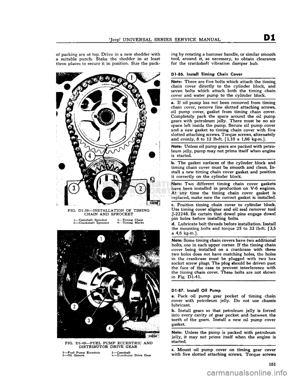
FIG.
Dl-39—INSTALLATION
OF
TIMING
CHAIN
AND
SPROCKET
1—
Camshaft
Sprocket 3—Timing
Chain
2—
Crankshaft
Sprocket 4—Timing
Marks
FIG.
Dl-40—FUEL
PUMP
ECCENTRIC
AND
DISTRIBUTOR
DRIVE GEAR
1—
Fuel
Pump
Eccentric
3—Camshaft
2—
Oil
Groove 4—Distributor Drive
Gear
ing by rotating a hammer handle, or similar smooth
tool, around it, as necessary, to obtain clearance
for the crankshaft vibration damper hub.
Dl-86.
Install
Timing
Chain
Cover
Note:
There
are five
bolts
which attach the timing
chain
cover directly to the cylinder block, and seven
bolts
which attach both the timing chain
cover and water pump to the cylinder block.
a.
If oil pump has not been removed from timing
chain
cover, remove fine slotted attaching screws,
oil
pump cover, gasket from timing chain cover. Completely pack the space around the oil pump gears with petroleum jelly.
There
must be no air
space left inside the pump. Secure oil pump cover
and
a new gasket to timing chain cover with five slotted attaching screws. Torque screws, alternately
and
evenly, 8 to 12 lb-ft [1,10 a 1,66 kg-m.].
Note:
Unless oil pump gears are packed with petro
leum jelly, pump may not prime itself when
engine
is started.
b.
The gasket surfaces of the cylinder block and
timing chain cover must be smooth and clean. In
stall
a new timing chain cover gasket and position
it
correctly on the cylinder block.
Note:
Two different timing chain cover gaskets
have been installed in production on V-6 engines.
At
any time the timing chain cover gasket is
replaced,
make sure the correct gasket is installed.
c.
Position timing chain cover to cylinder block.
Use
timing cover aligner and oil seal remover tool J-22248. Be certain that dowel pins
engage
dowel
pin
holes
before installing bolts.
d.
Lubricate
bolt threads before installation.
Install
the mounting
bolts
and torque 25 to 33 lb-ft. [3,5
a
4,6 kg-m.].
Note:
Some timing chain covers have two additional
bolts, one in each upper corner. If the timing chain
cover being installed on a crankcase with
these
two
holes
does
not have matching holes, the
holes
in
the crankcase must be plugged with two hex
socket screw plugs. The plug should be driven past
the face of the case to prevent interference with the timing chain cover. These
bolts
are not shown
in
Fig. Dl-41.
D1-87.
Install
Oil Pump
a.
Pack
•
oil pump gear pocket of timing chain
cover with petroleum jelly. Do not use chassis
lubricant.
b.
Install
gears so that petroleum jelly is forced
into every cavity of gear pocket and
between
the
teeth
of the gears.
Install
a new oil pump cover gasket.
Note:
Unless the pump is packed with petroleum
jelly,
it may not prime itself when the
engine
is
started.
c.
Mount oil pump cover on timing gear cover
with
five slotted attaching screws. Torque screws 101
Page 102 of 376
![JEEP CJ 1953 Owners Manual
Dl
DAUNTLESS
V-6
ENGINE
FIG.
Dl-41—WATER
PUMP
AND
TIMING CHAIN COVER BOLT LOCATION
Cover
Bolts
alternately and evenly 8 to 12 lb-ft. [1,10 a 1,66
kg-m.].
Dl-88.
Install
Cranksh JEEP CJ 1953 Owners Manual
Dl
DAUNTLESS
V-6
ENGINE
FIG.
Dl-41—WATER
PUMP
AND
TIMING CHAIN COVER BOLT LOCATION
Cover
Bolts
alternately and evenly 8 to 12 lb-ft. [1,10 a 1,66
kg-m.].
Dl-88.
Install
Cranksh](/img/16/57040/w960_57040-101.png)
Dl
DAUNTLESS
V-6
ENGINE
FIG.
Dl-41—WATER
PUMP
AND
TIMING CHAIN COVER BOLT LOCATION
Cover
Bolts
alternately and evenly 8 to 12 lb-ft. [1,10 a 1,66
kg-m.].
Dl-88.
Install
Crankshaft
Vibration
Damper
a.
Lubricate
the vibration damper hub
before
in
stallation to prevent
damage
to the crankshaft
front oil seal during installation and when the
engine
is first started.
b.
Install
the vibration damper on the crankshaft.
Secure it with its attaching flat washer and screw.
Torque
the screw to a minimum of 140 lb-ft.
[19,35
kg-m.].
Dl-89.
Install
Crankshaft Pulley
Secure the crankshaft pulley to the crankshaft
vibration
damper with six screws. Torque screws 18 to 25 lb-ft. [2,5 a 3,4 kg-m.].
Dl-90.
Install
Oil
Level
Dipstick
Insert
oil level dipstick
into
the dipstick tube.
Dl-91.
Install
Oil
Pressure Sending Unit
Install
oil pressure sending unit in cylinder block.
Connect electrical wiring harness to unit.
Dl-92.
Install Starting Motor
Secure starting motor and
solenoid
assembly to
the flywheel housing and cylinder block with two attaching screws. Torque screw, which attaches this
assembly to the flywheel housing, 30 to 40 lb-ft. [4,1 a 5,5 kg-m.]. Torque screw, which attaches
bracket
to cylinder block, 10 to 12 lb-ft. [1,4 a 1,7 kg-m.].
Dl-93.
Install
Oil
Filter
Install
a new oil filter
element
at oil filter nipple,
at
left
side
of timing chain cover. Torque 10 to 15 lb-ft. [1,38 a 2,07 kg-m.].
D1-94. Install Water Pump
Be
certain that mating surfaces of the water pump
and
timing chain cover are clean.
Install
a new
gasket
on the pump flange. Secure the pump and
alternator adjustment bracket to the cover with
nine attaching bolts. Torque
bolts
6 to 8 lb-ft. [0,83 a 1,10 kg-m.]. Refer to Fig. Dl-41.
D1-9S.
Install
Cooling Fan
Secure the cooling fan, fan hub, and fan drive
pulley to the water pump shaft
flange
with four
attaching screws. Torque screws 17 to 23 lb-ft. [2,35 a 3,18 kg-m.].
Dl-96.
Install
Alternator
and Fan
Belt
Mount the alternator and bracket assembly on
right
cylinder head with two attaching screws.
Torque
screws 30 to 40 lb-ft. [4,1 a 5,5 kg-m.].
Fasten
the alternator
loosely
to its adjustment
bracket
with attaching flat washer and nut.
Install
the fan
belt
on its pulleys. Pivot the alternator
outward,
away from cylinder block, to apply fan
belt
tension. Adjust fan
belt
tension to 80 lb. [36,2 kg.];
tighten
alternator-to-adjustment bracket
nut to secure adjustment
setting.
Connect wiring
harness to alternator.
Dl-97.
Install
Fuel Pump
Install
two mounting
bolts
and new
gasket
on
flange
of fuel pump. Secure pump to timing chain cover with screws; torque screws 17 to 23 lb-ft. [2,35 a 3,8 kg-m.]. Connect
output
fuel line to
pump.
Dl-98.
Install Exhaust Manifold
Secure each of two exhaust manifolds to corre
sponding cylinder head with five attaching screws,
and
one nut. Torque screws and nut 15 to 20 lb-ft. [2,07 a 2,8 kg-m.]. See Fig. Dl-42.
Dl-99.
Install Distributor
Insert
distributor drive gear
into
distributor mount-
FIG.
Dl-42—EXHAUST
MANIFOLD INSTALLATION
1—Torque
Bolts—15
to 20
lb-ft.
[2,07 a 2,8
kg-m.]
102
Page 105 of 376
'Jeep'
UNIVERSAL
SERIES SERVICE
MANUAL
Dl
Dl-104.
SERVICE
DIAGNOSIS
Poor Fuel Economy
Ignition Timing Late or Spark Advance Inoperative
Carburetor
Float Setting Too High
Accelerator Pump Improperly Adjusted
Fuel
Pump Pressure High
Fuel
Line
Leakage
Fuel
Pump Diaphragm Leakage
Cylinder
Compression Low
Valves Do Not Seat Properly
Spark
Plugs
Defective
Spark
Plug Cables
Defective
Ignition
Coil
or Capacitor
Defective
Carburetor
Air Cleaner Dirty
Brakes
Drag
Wheel Alignment Incorrect
Tire
Pressure Incorrect Odometer Inaccurate
Fuel
Tank
Cap Clogged or
Defective
Muffler or Exhaust Pipe Clogged or Bent
Lack
of
Power
Cylinder
Compression Low
Ingitdon Timing Late
Carburetor
or
Fuel
Pump Clogged or
Defective
Fuel
Lines Clogged
Air
Cleaner Restricted
Engine Temperature High Valves Do Not Seat Property
Valve
Timing Late Intake Manifold or Cylinder Head
Gasket Leaks
Muffler or Exhaust Pipe Clogged or Bent
Spark
Plugs Dirty or
Defective
Breaker
Point Gap Incorrect
Breaker
Points
Defective
Ignition
Coil
or Capacitor
Defective
Electrical
Connection Loose
Broken
Valve Spring
Broken
Piston Ring or Piston
Cylinder
Head Gasket
Defective
Distributor Cap Cracked
Low
Compression
Valves Not Seating Properly Piston Rings Seal Poorly
Valve
Spring Weak or Broken
Cylinder
Scored or Worn
Piston Clearance Too Great
Cylinder
Head Gasket Leaks
Burned
Valves and
Seats
Valves Stick or Are Too Loose in Guides
Valve
Timing Incorrect
Valve
Head and Seat Have Excessive Carbon
Engine Overheats
Valve
Spring Weak or Broken
Valve
Lifter Seized or Collapsed
Exhaust
System Clogged
Valves Sticking
Valve
Stem Warped
Valve
Stem Carbonized or Scored
Valve
Stem Clearance Insufficient in Guide
Valve
Spring Weak or Broken
Valve
Spring Distorted
Oil
Contaminated
Overheating
Cooling System Inoperative
Thermostat Inoperative Ignition Timing Incorrect
Valve
Timing Incorrect
Carbon
Accumulation Excessive
Fan
Belt Loose
Muffler or Exhaust Pipe Clogged or Bent
Oil
System Failure
Piston Rings Worn or Scored
Popping,
Spitting,
Detonation
Ignition Timing Incorrect
Carburetion
Improper
Carbon
Deposit
in Combustion
Chambers Excessive
Valves Not Seating Properly
Valve
Spring Broken
Spark
Plug Electrodes Burned
Water or Dirt in
Fuel
Fuel
Line
Clogged
Valve
Timing Incorrect
Excessive
Oil
Consumption
Piston Rings Stuck in Grooves, Weak,
Worn,
Broken, or Incorrectly Fitted
Crankshaft
Main Bearings or
Connecting Rod Bearings Have
Excessive Clearance
Gaskets or Oil Seals
Leak
Cylinder
Bores Worn, Scored,
Out-of-Round or Tapered
Pistons Have Too Great Clearance to Cylinder Bores
Connecting Rods Misaligned High Road Speed
High Temperature
Crankcase
Ventilation System Inoperative
Bearing Failure
Crankshaft
Bearing Journal Rough or Out-of-Round
Oil
Level Low
Oil
Leakage
Oil
Dirty
Oil
Pressure Low or Lacking
(Oil
Pump Failure)
Drilled
Passages
in Crankshaft or
Crankcase
Clogged
Oil
Screen Dirty
Connecting Rod Bent 105
Page 109 of 376
'Jeep*
UNIVERSAL SERIES SERVICE
MANUAL
E
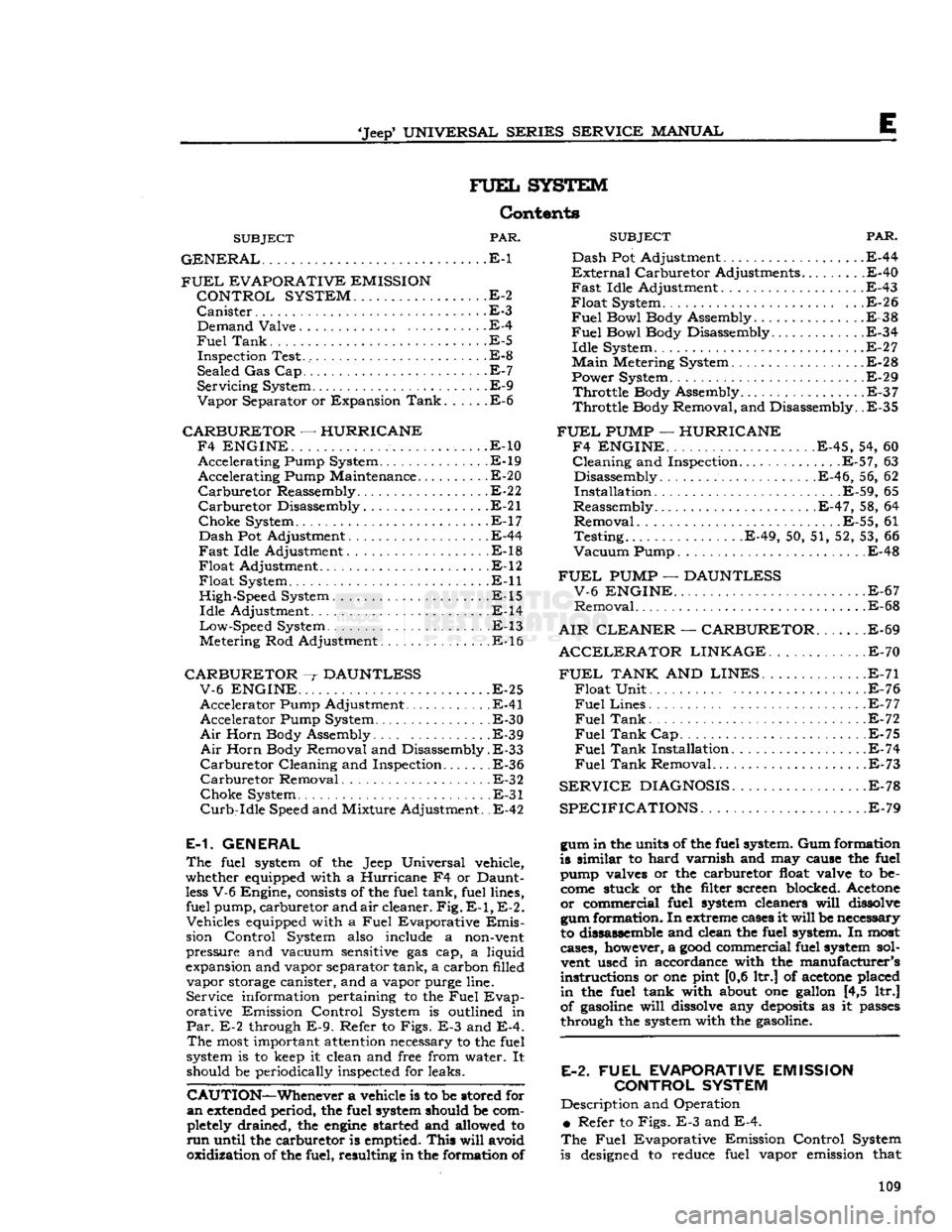
FUEL
SYSTEM
Contents
SUBJECT
PAR.
GENERAL
E-1 Dash
FUEL
EVAPORATIVE EMISSION
?*^r
CONTROL SYSTEM
..E-2
Canister
.E-3 . Demand Valve E-4
Fuel
Tank.
.E-5
Inspection Test. E-8
Sealed Gas Cap. E-7
Servicing
System E-9
Vapor
Separator or Expansion
Tank
E-6
CARBURETOR
—
HURRICANE F4 ENGINE.
. .
......
..... ,. . .E-10 Accelerating Pump System.............. .E-19 Accelerating Pump Maintenance E-20
Carburetor
Reassembly
E-2
2
Carburetor
Disassembly E-21
Choke
System E-17
Dash
Pot Adjustment E-44
Fast
Idle Adjustment E-18
Float
Adjustment E-12
Float
System. E-ll
High-Speed System . .E-15
Idle
Adjustment .E-14
Low-Speed
System . E-13
Metering Rod Adjustment E-16
CARBURETOR
~r
DAUNTLESS V-6 ENGINE
.E-25
Accelerator Pump Adjustment E-41 Accelerator Pump System. . E-30
Air
Horn Body Assembly E-39
Air
Horn Body Removal and Disassembly.
E-33
Carburetor
Cleaning and Inspection E-36
Carburetor
Removal E-32
Choke
System E-31
Curb-Idle
Speed and Mixture Adjustment. .E-42
E-1. GENERAL
The
fuel system of the Jeep Universal vehicle,
whether equipped with a Hurricane F4 or Daunt
less
V-6 Engine,
consists
of the fuel tank, fuel lines, fuel pump, carburetor and
air
cleaner.
Fig. E-1, E-2.
Vehicles equipped with a
Fuel
Evaporative
Emis
sion Control System
also
include a
non-vent
pressure and vacuum
sensitive
gas cap, a liquid
expansion and vapor separator tank, a carbon filled vapor
storage
canister, and a vapor purge line. Service information pertaining to the
Fuel
Evap
orative Emission Control System is outlined in
Par.
E-2 through
E-9.
Refer to Figs. E-3 and E-4.
The
most
important
attention
necessary to the fuel
system is to
keep
it clean and free from water. It should be periodically inspected for leaks.
CAUTION—Whenever
a vehicle is to be stored for
an
extended
period, the fuel system should be com
pletely
drained, the
engine
started and allowed to
run
until the carburetor is emptied.
This
will
avoid
oxidization of the fuel, resulting in the formation of
SUBJECT
PAR.
Pot Adjustment .E-44
nal
Carburetor Adjustments.........E-40
Idle
Adjustment
.
E-43 System . . .E-26
Bowl
Body Assembly E-38
Fuel
Bowl Body Disassembly E-34
Idle
System E-27
Main
Metering System E-28
Power System . E-29
Throttle
Body Assembly .E-37
Throttle
Body Removal, and Disassembly. .E-35
FUEL
PUMP
—
HURRICANE F4 ENGINE.
E-45, 54, 60
Cleaning
and Inspection.............
.E-57,
63 Disassembly E-46, 56, 62
Installation E-59, 65
Reassembly
.E-47,
58, 64
Removal
E-55, 61
Testing.
E-49, 50, 51, 52, 53, 66
Vacuum
Pump E-48
FUEL
PUMP
—
DAUNTLESS V-6 ENGINE
E-67
Removal
E-68
AIR CLEANER
—
CARBURETOR
E-69
ACCELERATOR
LINKAGE
.E-70
FUEL
TANK
AND
LINES
E-71
Float
Unit . .E-76
Fuel
Lines E-77
Fuel
Tank
. . .E-72
Fuel
Tank
Cap E-75
Fuel
Tank
Installation. E-74
Fuel
Tank
Removal E-73
SERVICE
DIAGNOSIS
E-78
SPECIFICATIONS.
E-79
gum in the units of the fuel system. Gum formation
is similar to hard varnish and may cause the fuel
pump valves or the carburetor
float
valve to be
come
stuck or the filter screen blocked. Acetone or commercial fuel system cleaners
will
dissolve
gum formation. In
extreme
cases
it
will
be necessary
to dissassemble and clean the fuel system. In
most
cases, however, a
good
commercial fuel system sol
vent
used in accordance with the manufacturer's
instructions or one pint [0,6 ltr.] of
acetone
placed
in
the fuel tank with
about
one gallon [4,5 ltr.]
of
gasoline
will
dissolve
any
deposits
as it
passes
through the system with the
gasoline.
E-2.
FUEL
EVAPORATIVE EMISSION CONTROL SYSTEM
Description and Operation
•
Refer to Figs. E-3 and E-4.
The
Fuel
Evaporative Emission Control System
is
designed
to reduce fuel vapor emission that 109