alternator JEEP CJ 1953 Owner's Guide
[x] Cancel search | Manufacturer: JEEP, Model Year: 1953, Model line: CJ, Model: JEEP CJ 1953Pages: 376, PDF Size: 19.96 MB
Page 202 of 376
H
ELECTRICAL
SYSTEM
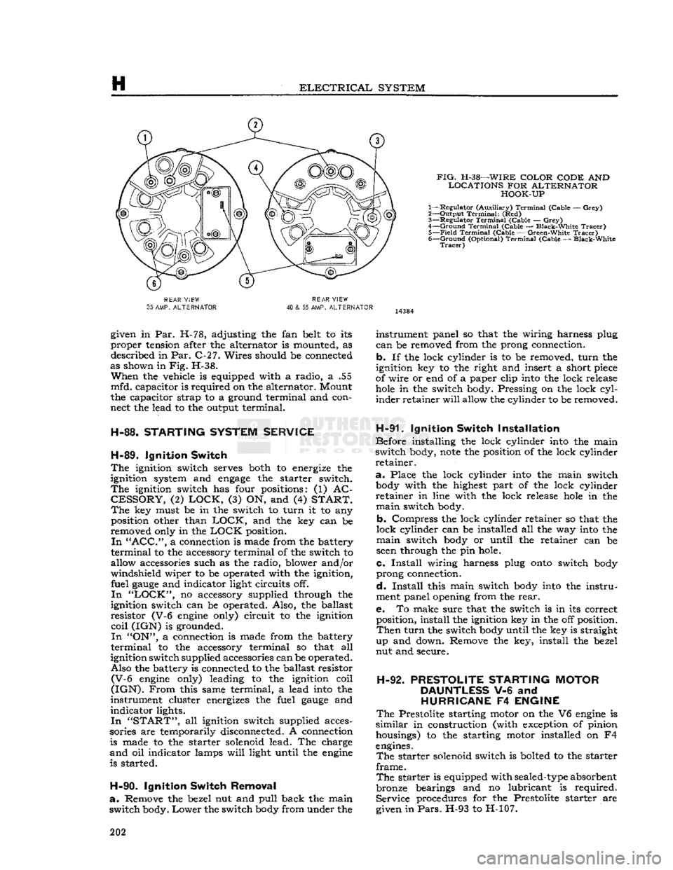
FIG.
H-38—WIRE
COLOR CODE
AND
LOCATIONS
FOR
ALTERNATOR HOOK-UP
1— Regulator (Auxiliary)
Terminal
(Cable —
Grey)
2— Output
Terminal:
(Red)
3—
Regulator
Terminal
(Cable —
Grey)
4—
Ground
Terminal
(Cable — Black-White
Tracer)
5—
Field
Terminal
(Cable — Green-White
Tracer)
6—
Ground
(Optional)
Terminal
(Cable — Black-White
Tracer)
REAR
VIEW
35
AMP.
ALTERNATOR
REAR
VIEW
40
& 55 AMP.
ALTERNATOR
given in Par. H-78, adjusting the fan belt to its
proper tension after the alternator is mounted, as described in Par. C-27. Wires should be connected
as shown in Fig. H-38.
When
the vehicle is equipped with a radio, a .55
mfd. capacitor is required on the alternator. Mount
the capacitor strap to a ground terminal and con
nect the lead to the output terminal.
H-88.
STARTING
SYSTEM
SERVICE
H-89.
Ignition
Switch
The
ignition switch serves both to energize the
ignition system and
engage
the starter switch.
The
ignition switch has four positions: (1) AC
CESSORY,
(2)
LOCK,
(3) ON, and (4)
START. The
key must be in the switch to turn it to any position other than
LOCK,
and the key can be
removed only in the
LOCK
position.
In "ACC",
a connection is made from the battery
terminal
to the accessory terminal of the switch to
allow accessories such as the radio, blower and/or
windshield wiper to be operated with the ignition, fuel
gauge
and indicator light circuits off.
In "LOCK",
no accessory supplied through the
ignition switch can be operated. Also, the ballast
resistor (V-6
engine
only) circuit to the ignition
coil
(IGN) is grounded.
In
"ON", a connection is made from the battery
terminal
to the accessory terminal so that all
ignition switch supplied accessories can be operated. Also the battery is connected to the ballast resistor
(V-6
engine
only) leading to the ignition coil
(IGN).
From
this same terminal, a lead
into
the
instrument cluster energizes the fuel
gauge
and
indicator lights.
In "START",
all ignition switch supplied acces
sories are temporarily disconnected. A connection is made to the starter solenoid lead. The charge
and
oil indicator lamps
will
light until the
engine
is started.
H-90.
Ignition
Switch
Removal
a.
Remove the bezel nut and pull back the main
switch body.
Lower
the switch
body
from under the instrument panel so that the wiring harness plug
can
be removed from the prong connection,
b. If the lock cylinder is to be removed, turn the
ignition key to the right and insert a short
piece
of wire or end of a paper clip
into
the lock release
hole
in the switch body. Pressing on the lock
cyl
inder retainer
will
allow the cylinder to be removed.
H-91.
Ignition
Switch
Installation
Before installing the lock cylinder
into
the main
switch body,
note
the position of the lock cylinder
retainer.
a.
Place the lock cylinder
into
the main switch
body
with the highest part of the lock cylinder
retainer in line with the lock release
hole
in the
main
switch body.
b. Compress the lock cylinder retainer so that the
lock cylinder can be installed all the way
into
the
main
switch
body
or until the retainer can be
seen
through the pin hole.
c.
Install
wiring harness plug
onto
switch
body
prong connection.
d.
Install
this main switch
body
into
the instru
ment panel opening from the
rear.
e. To make sure that the switch is in its correct position, install the ignition key in the off position.
Then
turn the switch
body
until the key is straight
up and down. Remove the key, install the bezel
nut and secure.
H-92.
PRESTOLITE
STARTING
MOTOR
DAUNTLESS
V-6 and
HURRICANE
F4
ENGINE
The
Prestolite starting motor on the V6
engine
is
similar
in construction (with exception of pinion housings) to the starting motor installed on F4
engines.
The
starter solenoid switch is bolted to the starter
frame.
The
starter is equipped with
sealed-type
absorbent
bronze bearings and no lubricant is required. Service procedures for the Prestolite starter are
given in
Pars.
H-93 to H-107. 202
Page 203 of 376
'Jeep*
UNIVERSAL
SERIES SERVICE
MANUAL
H
13406
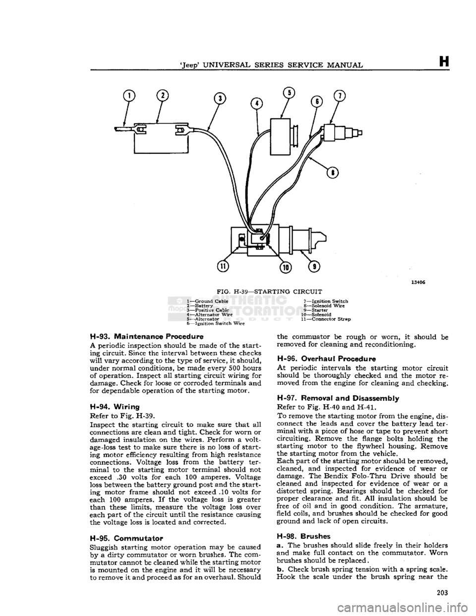
FIG.
H-39—STARTING
CIRCUIT
1—
Ground
Cable
2—
Battery
3—
Positive Cable
4—
Alternator
Wire
5—
Alternator
6— Ignition Switch
Wire
H-93.
Maintenance Procedure
A
periodic inspection should be made of the start ing circuit. Since the interval
between
these
checks
will
vary according to the type of service, it should, under normal conditions, be made every 500 hours
of operation. Inspect all starting circuit wiring for damage.
Check
for
loose
or corroded terminals and
for dependable operation of the starting motor.
H-94.
Wiring
Refer
to Fig. H-39. Inspect the starting circuit to make sure that all
connections are clean and tight.
Check
for worn or damaged insulation on the wires. Perform a volt
age-loss
test
to make sure there is no
loss
of start ing motor efficiency resulting from high resistance
connections. Voltage
loss
from the battery ter
minal
to the starting motor terminal should not
exceed .30 volts for each 100 amperes. Voltage
loss
between
the battery ground
post
and the starting motor frame should not exceed .10 volts for
each 100 amperes. If the
voltage
loss
is greater
than
these
limits, measure the
voltage
loss
over
each part of the circuit until the resistance causing the
voltage
loss
is located and corrected.
H-95.
Commutator
Sluggish starting motor operation may be caused by a dirty commutator or worn brushes. The commutator cannot be cleaned while the. starting motor is mounted on the
engine
and it
will
be necessary
to remove it and proceed as for an overhaul. Should 7— Ignition Switch
8— Solenoid
Wire
9—
Starter
10— Solenoid
11—
Connector
Strap
the commuator be rough or worn, it should be
removed for cleaning and reconditioning.
H-96.
Overhaul Procedure
At
periodic intervals the starting motor circuit
should be thoroughly checked and the motor re moved from the
engine
for cleaning and checking.
H-97.
Removal and Disassembly
Refer
to Fig. H-40 and H-41.
To
remove the starting motor from the engine, dis
connect the leads and cover the battery lead ter
minal
with a piece of
hose
or tape to prevent short
circuiting.
Remove the flange
bolts
holding the starting motor to the flywheel housing. Remove
the starting motor from the vehicle.
Each
part of the starting motor should be removed, cleaned, and inspected for evidence of wear or
damage. The Bendix
Folo-Thru
Drive should be
cleaned and inspected for evidence of wear or a distorted spring. Bearings should be checked for
proper clearance and fit. All insulation should be
free of oil and in
good
condition. The armature,
field coils, and brushes should be checked for
good
ground and lack of open circuits.
H-98.
Brushes
a.
The brushes should slide freely in their holders
and
make full contact on the commutator. Worn
brushes should be replaced.
b.
Check
brush spring tension with a spring scale.
Hook the scale under the brush spring near the 203
Page 220 of 376
H
ELECTRICAL
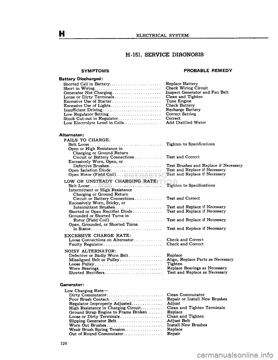
SYSTEM H-15L SERVICE
DIAGNOSIS
SYMPTOMS
Battery
Discha
rged: Shorted
Cell
in Battery......... Short in Wiring..
•
Generator Not Charging ,
Loose or Dirty Terminals
Excessive Use of Starter Excessive Use of Lights...... Insufficient Driving.........
Low
Regulator
Setting.......
Stuck
Cut-out in Regulator. ..
Low
Electrolyte
Level
in Cells
Alternator:
FAILS
TO
CHARGE:
Belt Loose Open or High Resistance in
Charging
or Ground Return
Circuit
or Battery Connections............
Excessively Worn, Open, or
Defective
Brushes.
Open Isolation
Diode.
Open Rotor (Field
Coil)
LOW
OR
UNSTEADY
CHARGING RATE:
Belt Loose.... Intermittent or High Resistance
Charging
or Ground Return
Circuit
or Battery Connections
Excessively Worn, Sticky, or Intermittent Brushes
Shorted or Open Rectifier
Diode
Grounded
or Shorted
Turns
in Rotor (Field
Coil)
Open,
Grounded, or Shorted
Turns
in
Stator
EXCESSIVE
CHARGE RATE:
Loose Connections on Alternator...........
Faulty
Regulator
NOISY
ALTERNATOR:
Defective
or Badly Worn Belt
Misaligned Belt or Pulley
Loose Pulley
Worn
Bearings.
Shorted Rectifiers
Generator:
Low
Charging Rate—
Dirty
Commutator
Poor Brush Contact.
................
Regulator Improperly Adjusted.......
High
Resistance in Charging
Circuit...
Ground
Strap Engine to Frame Broken
Loose or Dirty Terminals Slipping Generator Belt
Worn
Out Brushes
Weak
Brush Spring Tension..........
Out
of Round Commutator
PROBABLE REMEDY
Replace Battery
Check
Wiring
Circuit
Inspect Generator and Fan Belt
Clean
and Tighten
Tune
Engine
Check
Battery
Recharge Battery
Correct
Setting
Correct
Add
Distilled Water
Tighten to
Specifications
Test
and Correct
Test
Brushes and Replace if Necessary
Test
and Replace if Necessary
Test
and Replace if Necessary
Tighten to
Specifications
Test
and Correct
Test
and Replace if Necessary
Test
and Replace if Necessary
Test
and Replace if Necessary
Test
and Replace if Necessary
Check
and Correct
Check
and Correct
Replace
Align,
Replace Parts as Necessary Tighten Replace Bearings as Necessary
Test
and Replace as Necessary
Clean
Commutator
Repair
or Install New Brushes
Adjust
Clean
and Tighten Terminals Replace
Clean
and Tighten
Adjust
Belt
Install
New Brushes
Replace
Repair
220
Page 223 of 376
'Jeep'
UNIVERSAL SERIES SERVICE
MANUAL
H
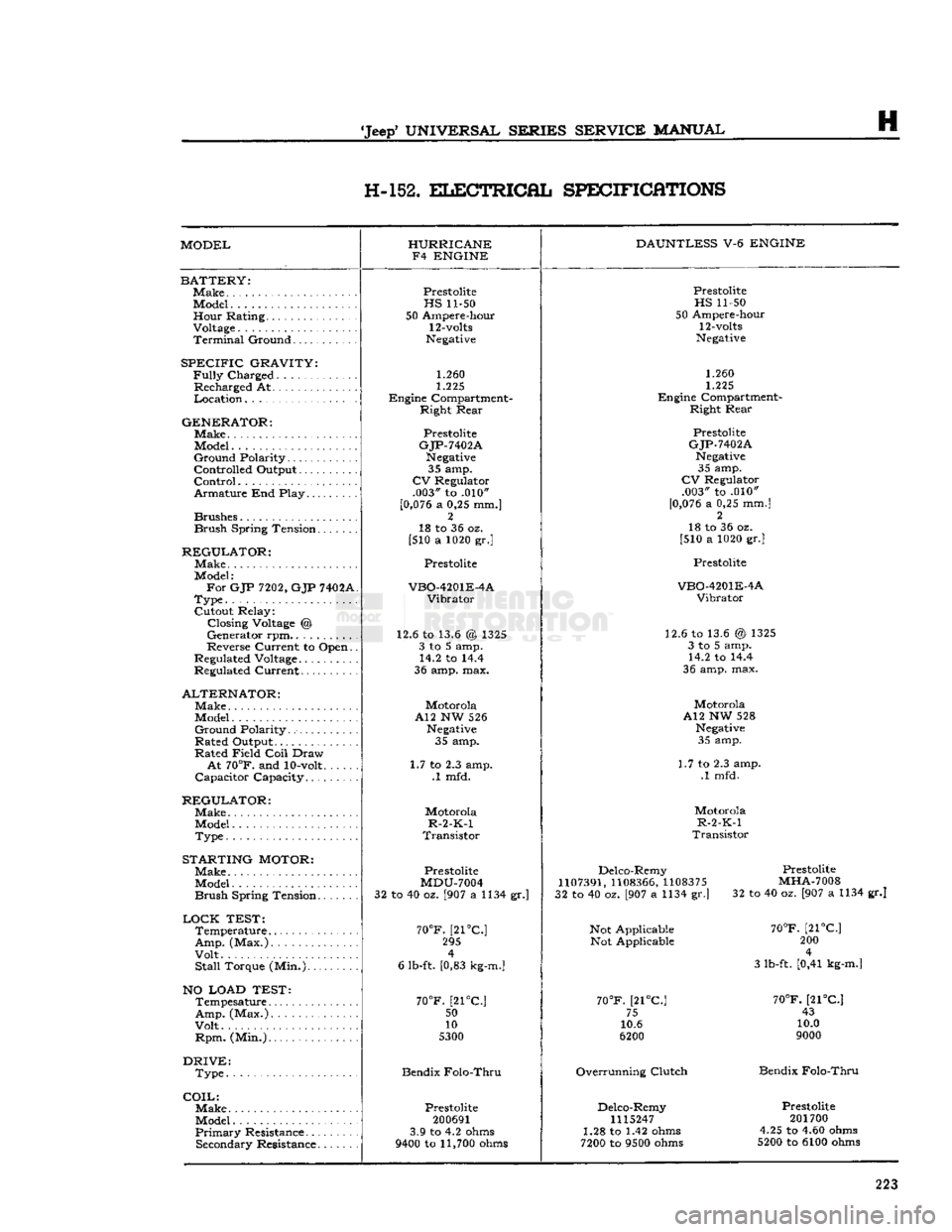
H-152.
ELECTRICAL
SPECIFICATIONS
MODEL HURRICANE
F4 ENGINE DAUNTLESS
V-6
ENGINE
BATTERY:
Make
Model Hour Rating.
Voltage
Terminal
Ground
SPECIFIC
GRAVITY:
Fully
Charged
Recharged At
Location
GENERATOR:
Make.
Model
Ground
Polarity
Controlled Output
Control
Armature End Play
Brushes
Brush
Spring Tension
REGULATOR:
Make
Model:
For
GJP
7202,
GJP
7402A
Type
Cutout Relay: Closing
Voltage
@
Generator rpm..........
Reverse Current to Open.
Regulated
Voltage
Regulated Current
ALTERNATOR:
Make
Model
Ground
Polarity
Rated Output
Rated Field
Coil
Draw
At
70°F.
and
10-volt
Capacitor Capacity
REGULATOR:
Make
Model
Type
STARTING
MOTOR:
Make
Model
Brush
Spring Tension
LOCK
TEST:
Temperature
Amp.
(Max.)
Volt
Stall
Torque (Min.)
NO LOAD TEST:
Tempesature
Amp.
(Max.)
Volt
Rpm.
(Min.)
DRIVE:
Type
COIL:
Make.
Model
Primary
Resistance Secondary Resistance
Prestolite
HS
11-50
50 Ampere-hour
12-volts
Negative
1.260
1.225
Engine Compartment- Right Rear
Prestolite
GJP-7402A
Negative
35 amp.
CV
Regulator .003" to .010"
[0,076
a 0,25 mm.] 2
18 to 36 oz.
[510 a 1020 gr.]
Prestolite
VBO-4201E-4A
Vibrator
12.6 to 13.6 @ 1325 3 to 5 amp. 14.2 to 14.4
36 amp. max.
Motorola
A12 NW 526
Negative
35 amp.
1.7 to 2.3 amp. .1 mfd.
Motorola
R-2-K-1
Transistor
Prestolite
MDU-7004
32 to 40 oz. [907 a 1134 gr.]
70°F.
[21°C] 295 4
6 lb-ft. [0,83
kg-m.]
70°F.
[21°C.;
50
10
5300
Bendix Folo-Thru
Prestolite
200691
3.9 to 4.2
ohms
9400
to
11,700
ohms
Prestolite
HS
11-50
50 Ampere-hour
12-volts
Negative
1.260
1.225
Engine Compartment- Right Rear
Prestolite
GJP-7402A
Negative
35 amp.
CV
Regulator .003" to .010"
[0,076
a 0,25 mm.] 2
18 to 36 oz.
[510 a 1020 gr.]
Prestolite
VBO-4201E-4A
Vibrator
12.6 to 13.6 @ 1325 3 to 5 amp. 14.2 to 14.4
36 amp. max.
Motorola
A12 NW 528
Negative
35 amp.
1.7 to 2.3 amp. .1 mfd.
Motorola
R-2-K-1
Transistor
Delco-Remy
1107391,
1108366,
1108375
32 to 40 oz. [907 a 1134 gr.]
Not Applicable Not Applicable
70°F.
[21°C] 75
10.6
6200
Overrunning Clutch Delco-Remy
1115247
1.28 to 1.42
ohms
7200
to
9500
ohms
Prestolite
MHA-7008
32 to 40 oz. [907 a 1134 gr.]
70°F.
[21°C] 200 4
3 lb-ft. [0,41
kg-m.]
70°F.
[21°C] 43
10.0
9000
Bendix Folo-Thru
Prestolite
201700
4.25 to 4.60
ohms
5200
to 6100
ohms
223
Page 360 of 376
u
MISCELLANEOUS
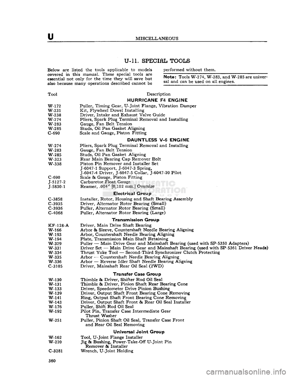
U-ll. SPECIAL TOOLS
Below are listed the
tools
applicable to
models
covered in this manual. These special
tools
are
essential not
only
for the
time
they
will
save
but
also
because
many
operations
described cannot be performed
without
them.
Note;
Tools W-274, W-283, and W-285 are univer
sal
and can be used on all
engines.
Tool
Description
HURRICANE
F4
ENGINE
W-172 Puller, Timing
Gear,
U-Joint Flange, Vibration Damper W-231 Kit, Flywheel Dowel Installing
W-238 Driver, Intake and Exhaust Valve Guide
W-2
74 Pliers, Spark Plug Terminal Removal and Installing W-283 Gauge, Fan Belt Tension W-285 Studs, Oil Pan Gasket Aligning
C-690 Scale and Gauge, Piston Fitting
DAUNTLESS
V-6
ENGINE
W-274 Pliers, Spark Plug Terminal Removal and Installing
W-283 Gauge, Fan Belt Tension W-285 Studs, Oil Pan Gasket Aligning W-323
Rear
Main Bearing Cap Remover Bolt
W-338 Piston Pin Remover and Installer Set
J-6047-1
Support, J-6047-3 Spring,
J-6047-4
Driver, J-6047-5
Collar,
J-6047-20
Pilot
C-690 Scale & Gauge, Piston Fitting
J-5127-2 Carburetor Float Gauge
J-5830-1
Reamer, .004"
[0,102
mm.] Oversize
Electrical
Group
C-3858 Installer, Rotor, Housing and Shaft Bearing Assembly
C-3935 Driver, Alternator Rotor Bearing (Small) C-3936 Puller, Alternator Rotor Bearing (Small)
C-4068 Puller, Alternator Rotor Bearing (Large)
Transmission
Group
KF-128-A
Driver, Main Drive Shaft Bearing W-166 Arbor &
Sleeve,
Countershaft
Needle
Bearing Aligning
W-193 Arbor, Countershaft
Needle
Bearing Aligning W-194 Plate, Transmission Main Shaft Retaining
W-329 Puller — Main Drive
Gear
and Mainshaft Bearing (used with SP-5350 Adapters)
W-331 Driver Set — Main Drive
Gear
and Mainshaft Bearing (used with SP-5361 Driver Heads)
W-334 Thrust Yoke Tool — Second-Third Synchronizer Clutch Protecting W-335 Arbor — Countershaft
Needle
Bearing Aligning
W-336 Arbor — Reverse Idler Shaft
Needle
Bearing Aligning
C-3105 Driver, Mainshaft
Rear
Oil Seal (2WD)
Transfer Case
Group
W-130 Thimble & Driver, Shifter Rod Oil Seal
W-131 Thimble & Driver, Pinion Shaft
Rear
Bearing Cone
W-133 Driver,
Speedometer
Drive Pinion Bushing W-139 Driver, Output Shaft Front Bearing Cone Removing
W-141 Ring, Output Shaft Front Bearing Cone Removing
W-143 Driver, Output Shaft Front &
Rear
Oil Seal Installer W-176 Puller, Shift Rod Oil Seal
W-192 Pilot Pin, Transfer Case Intermediate
Gear
Thrust
Washer
W-251 Puller, Pinion Shaft Oil Seal, Transfer Case Front and
Rear
Oil Seal Removing
Universal
Joint Group
W-162 Tool, U-Joint Flange Installer
W-220 Jig & Bushing, Power-Take-Off U-Joint Pin Remover & Installer
C-3281 Wrench, U-Joint Holding 360
Page 362 of 376
u
MISCELLANEOUS
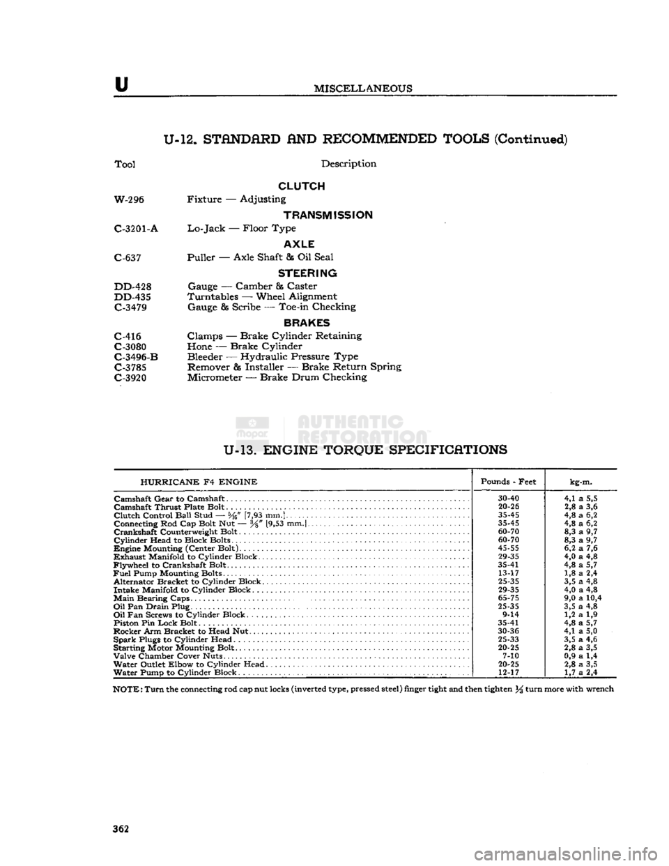
U-12.
STANDARD
AND
RECOMMENDED TOOLS
(Continued)
Tool
Description
CLUTCH
W-296 Fixture — Adjusting
TRANSMISSION
C-3201
- A
Lo-Jack
— Floor Type
AXLE
C-637 Puller — Axle Shaft & Oil Seal
STEERING
DD-428 Gauge — Camber & Caster
DD-435 Turntables — Wheel Alignment C-3479 Gauge & Scribe — Toe-in Checking
BRAKES
C-416 Clamps — Brake Cylinder Retaining C-3080 Hone — Brake Cylinder
C-3496-B Bleeder — Hydraulic Pressure Type C-3785 Remover & Installer — Brake Return Spring
C-3920 Micrometer — Brake Drum Checking
U-13.
ENGINE TORQUE SPECIFICATIONS HURRICANE
F4
ENGINE
Pounds - Feet
kg-m.
30-40
4,1
a
5,5
Camshaft
Thrust Plate Bolt
20-26
2,8
a
3,6
Clutch
Control
Ball
Stud — [7,93 mm.]
35-45
4,8
a
6,2
Connecting Rod Cap Bolt Nut — y8" [9,53 mm.|
35-45
4,8
a
6,2
60-70
8,3
a
9,7
Cylinder
Head to Block Bolts
60-70
8,3
a
9,7
45-55
6,2
a
7,6
29-35
4,0
a
4,8
Flywheel
to Crankshaft Bolt. 35-41
4,8
a
5,7
Fuel
Pump Mounting Bolts 13-17 1,8
a
2,4
Alternator Bracket to Cylinder Block.
25-35
3,5
a
4,8
29-35
4,0
a
4,8
Main
Bearing
Caps.
.
65-75
9,0
a
10,4
Oil
Pan
Drain
Plug
25-35
3,5
a
4,8
9-14 1,2
a
1,9
Piston Pin
Lock
Bolt 35-41
4,8
a
5,7
30-36
4,1
a
5,0
Spark
Plugs to Cylinder Head
25-33
3,5
a
4,6
Starting Motor Mounting Bolt.
20-25
2,8
a
3,5
7-10 0,9
a
1,4
Water
Outlet Elbow to Cylinder Head
20-25
2,8
a
3,5
Water
Pump to Cylinder Block 12-17
1,7
a
2,4
NOTE:
Turn
the connecting rod cap nut locks (inverted type, pressed
steel)
finger
tight
and then
tighten
% turn more with wrench
362
Page 363 of 376
'Jeep*
UNIVERSAL SERIES
SERVICE
MANUAL
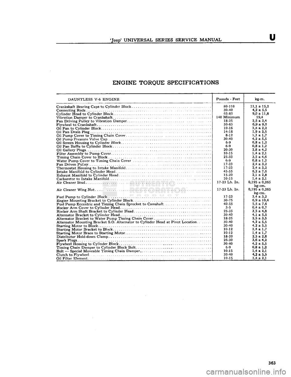
U ENGINE TORQUE SPECIFICATIONS
DAUNTLESS
V-6
ENGINE
Pounds
- Feet
kg-m.
80-110
11,1 a 15,2
30-40
4,2 a 5,5
65-85
9,0 a 11,8
140 Minimum 19,4
18-25 2,5 a 3,4
50-65
6,9 a 9,0
10-16 1,4 a 2,2
14-18 1,9 a 2,5
8-12 1,1 a 1,7
30-40
4,2 a 5,5
6-9 0,8 a 1,2
6-9 0,8 a 1,2
20-30
2,8 a 4,2
10-15 1,4 a 2,1
25-33
3,5 a 4,6
6-9 0,8 a 1,2
17-23 2,4 a 3,2
17-23 2,4 a 3,2
45-55
6,2 a 7,6
15-20 2,1 a 2,8
10-15 1,4 a 2,1
17-23
Lb.
In. 0,195 a
0,265
kg-cm.
17-23 Lb. In. 0,195 a
0,265
kg-cm.
17-23 2,4 a 3,2
50-75
6,9 a 10,4
40-55
5,5 a 7,6
3-5 0,4 a 0,7
25-35
3,5 a 4,8
30-40
4,1 a 5,5
18-25 2,5 a 3,5
30-40
4,2 a 5,5
30-40
4,2 a 5,5
10-12 1,4 a 1,7
10-12 1,4 a 1,7
18-20 2,5 a 2,8
26-30
3,6 a 4,2
30-40
4,2 a 5,5
6-9 0,8 a 1,2
10-15 1,4 a 2,1
30-40
4,2 a 5,5
10-15 1,4 a 2,1
Crankshaft
Bearing Caps to Cylinder Block.
Connecting Rods.
Cylinder
Head to Cylinder Block
Vibration Damper to Crankshaft
Fan
Driving Pulley to Vibration Damper
Flywheel to Crankshaft
Oil
Pan to Cylinder Block
Oil
Pan Drain Plug
Oil
Pump Cover to Timing Chain Cover. . .
Oil
Pump Pressure Valve Cap
Oil
Screen Housing to Cylinder Block
Oil
Pan Baffle to Cylinder Block
Oil
Gallery Plugs.
Filter
Assembly to Pump Cover
Timing
Chain Cover to Block
Water Pump Cover to Timing Chain Cover.
Fan
Driven Pulley Thermostat Housing to Intake Manifold. . . Intake Manifold to Cylinder Head
Exhaust
Manifold to Cylinder Head
Carburetor
to Intake Manifold
Air
Cleaner Stud
Air
Cleaner Wing Nut.
Fuel
Pump to Cylinder Block . . Engine
Mounting
Bracket to Cylinder Block
Fuel
Pump Eccentric and Timing Chain Sprocket to Camshaft
Rocker Arm Cover to Cylinder Head Rocker Arm Shaft Bracket to Cylinder Head
Alternator Bracket to Cylinder Head
Alternator Bracket to Water Pump Timing Chain Cover Alternator
Mounting
Bracket S.O. Alternator to Cylinder Head at Pivot Location.
Starting Motor to Block Starting Motor Bracket to Block
Starting Motor Brace to Starting Motor Distributor
Hold-down
Clamp
Spark
Plugs
Flywheel Housing to Cylinder Block
Timing
Chain Damper to Cylinder Block Bolt.
Bolt — Special
Moveable
Timing Chain Damper
Clutch
to Flywheel
Oil
Filter Element .' 363
Page 371 of 376
'Jeep'
UNIVERSAL
SERIES SERVICE
MANUAL
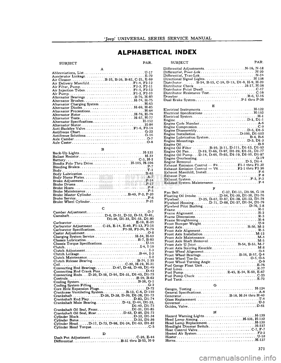
ALPHABETICAL INDEX
SUBJECT PAR.
SUBJECT
PAR.
Abbreviations,
List
U-17 Accelerator Linkage E-70
Air
Cleaner B-25, B-26, B-82, C-21, E-69
Air
Delivery Manifold Fl-4, F2-12
Air
Filter, Pump • F2-3, F2-11
Air
Injection Tubes Fl-5, F2-13
Air
Pump Fl-2, F2-10
Alternator Bearings B-76, H-80
Alternator Brushes H-74, H-75
Alternator Charging System •
•
H-63
Alternator
Diodes
H-69, H-85
Alternator Precautions H-64 Alternator Rotor H-76, H-79
Alternator Tests H-67, H-77 Alternator Specifications H-l 52
Alternator Stator H-84
Anti-Backfire
Valve Fl-6, F2-14
Antifreeze
Chart
• G-22 Antifreeze
Solutions
- G-16
Axle Camber O-l
Axle Caster 0-8
Back-Up
Lights H-135
Ballast
Resistor. H-32 Battery C-3, H-2 Bendix Folo-Thru Drive H-105, H-106
Bleeding Brakes P-7
Body T-l Body Lubrication. B-65 Body Name Plates ' A-7
Brake
Adjustment P-14
Brake
Drums. • .P-17
Brake
Hoses
P-8
Brake
Maintenance . P-5
Brake
Master Cylinder B-40, P-2, P-20
Brake
Service P-6
Brake
Wheel Cylinder • P-21
Camber
Adjustment 0-7
Camshaft D-6, D-51, D-52, D-53, D-81, Dl-26, Dl-33, Dl-55, Dl-80
Carburetor
E-10, E-25
Carburetor
Adjustment C-25, E-14, E-40,
Fl-13,
F2-16
Carburetor
Specifications .Fl-38, F2-34, E-79
Caster
Adjustment 0-8
Charging
System Service. .H-34, H-63
Chassis
Lubrication B-7, B-83
Chassis
Torque Specifications U-14
Clutch
1-4, MO
Clutch
Adjustment 1-3
Clutch
Linkage B-44, 1-3
Clutch
Maintenance .. 1-2
Clutch
Release Bearing B-74, 1-25
Coil
C-20, H-19, H-31 Connecting Rod Bearings D-47, D-48, D-49, Dl-49 Connecting Rod
Crank
Pins D-42
Connecting Rods... .D-20, D-50, D-95, Dl-31, Dl-45, Dl-75
Controls B-59, B-62
Cooling System B-28, G-l Cooling System Filling G-2
Core
Hole Expansion Plugs D-72
Crankcase
Ventilating System B-13, C-6, D-110
Crankshaft
D-26, D-38, D-39, Dl-38, Dl-73
Crankshaft
End Play. D-83, Dl-74
Crankshaft
Main Bearing D-43, D-44, Dl-32, Dl-40, Dl-73
Crankshaft
Oil Seal, Front Dl-21, Dl-85
Crankshaft
Oil Seal, Rear D-63, D-85, Dl-72
Cylinder
Block D-32, Dl-34
Cylinder
Bores D-35, Dl-36
Cylinder
Head D-17, D-73, D-98, Dl-24, Dl-63, Dl-82
Cylinder
Head Torque. C-5
Dash Pot Adjustment C-26, E-44
Differential B-51 thru B-53, N-9 Differential Adjustments N-16, N-18
Differential, Powr-Lok N-20
Differential,
Trac-Lok
N-24
Directional Signal Lights. . H-138
Distributor B-14, B-15, C-10, D-13, Dl-9, H-9, H-20 Distributor Check H-l7, H-28
Distributor Point Dwell C-17 Distributor Resistance Test C-16
Drawbar
.R-6, U-16
Dual
Brake System P-l thru P-26
Electrical
Instruments H-l22
Electrical
Specifications .H-l52
Electrical
System H-l Engine .
..D-l,
Dl-1
Engine Code Number A-6
Engine Compression .
.
C-9 Engine Disassembly . • .D-6, Dl-5 Engine Installation D-105, Dl-102
Engine Lubrication System B-4, B-6 Engine Mountings D-3, Dl-3
Engine Oil B-9
Engine Oil Filter B-10, B-ll,
D-lll,
Dl-13, Dl-93
Engine Oil Pan D-l9, D-66, D-97, Dl-29, Dl-51, Dl-77 Engine Oil Pump. . .D-14, D-65, D-93, Dl-19, Dl-50, Dl-87
Engine Overheating. G-l9 Engine Removal D-5, Dl-4.
Exhaust
Emission Control — F4 Fl-1 thru Fl-30
Exhaust
Emission Control — V6 F2-1 thru F2-36
Exhaust
Manifold, Install F-6
Exhaust
Pipe -
•
F-8
Exhaust
System F-2, F-3
Exhaust
System Maintenance F-4
Fan
Belt C-27, Dl-11, Dl-96, G-18
Floating Oil Intake. D-64, Dl-30, Dl-50, Dl-76 Flywheel D-25, D-67, D-87, Dl-28, Dl-52, Dl-78
Flywheel Housing. D-71, D-88, Dl-27, Dl-54, Dl-79
Flywheel Pilot Bushing D-70, 1-8
Frame
R-l
Frame
Alignment. R-2
Frame
Dimensions R-3
Frame
Straightening R-4
Front
Bumper Weight. • U-9
Front
Axle B-50, M-2
Front
Axle Alignment R-5
Front
Axle Installation • M-12
Front
Axle Maintenance M-3
Front
Axle Shaft Removal M-5
Front
Axle U-Joint B-54, B-55, M-7
Front
Axle Steering Knuckle M-&
Front
Wheel Alignment 0-4
Front
Wheel Bearings B-56, B-57, Q-4
Front
Wheel Toe-in 0-5, 0-6
Front
Wheel Turning Angle 0-9
Fuel
Gauge Float Unit F-76
Fuel
Lines - E-77
Fuel
Pump E-45, E-54, E-60, E-67
Fuel
Pump Check C-23
Fuel
Tank
E-72
G
Gauges, Testing H-l24
General
Specifications A-8
Generator B-16, H-34 thru H-40
Glass
Replacement • T-4
Governor. . .
•.
• U-3
Guides, Valve D"61
H
Hazard
Warning Lights H-139
Head Lamp Aiming H-131, H-132 Head Lamp Replacement H-130
Headlight Dimmer Switch H-l
2
7
Heat Control Valve C-7, F-7 Heated Air System • •
•
F2-2
Heater U-10
Horns.....
....H-137 371
Page 372 of 376
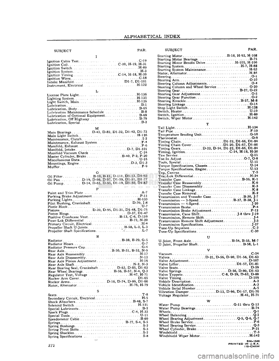
ALPHABETICAL
INDEX
SUBJECT
PAR.
SUBJECT
PAR.
Ignition Cable Test C-l9 Ignition
Coil
C-20, H-19, H-31
Ignition Switch H-89 Ignition System H-3
Ignition
Timing
C-14, H-18, H-30 Ignition Wires C-18
Intake Manifold '." Dl-7, Dl-101
Instrument, Electrical H-122
L
License Plate Light H-l36
Lighting
System H-l25
Light
Switch, Main . H-l 26
Lubrication
B-l
Lubrication,
Body B-65
Lubrication
Maintenance Schedule B-8
Lubrication
of Optional Equipment B-69
Lubrication,
Off Highway B-79
Lubrication,
Special. B-2
M
Main
Bearings D-43, D-82, Dl-32, Dl-42, Dl-73
Main
Light Switch. H-l26
Maintenance, Clutch 1-2 Maintenance, Exhaust System.,
-
F-4
Manifold, Exhaust -F-6 Manifold, Intake D-7, Dl-101
Manifold Vacuum Check. .C-24 Master Cylinder, Brake B-40, P-2, P-20
Miscellaneous Data U-16 Mountings, Engine • • •
-
D-3, Dl-3
Muffler. F-9
O
Oil
Filter B-10, B-ll,
D-lll,
Dl-13, Dl-93
Oil
Pan D-19, D-66, D-97, Dl-29, Dl-51, Dl-77
Oil
Pump. D-14, D-65, D-93, Dl-19, Dl-50, Dl-87
P
Paint and
Trim
Plate • • A-7
Parking
Brake Adjustment P-ll
Parking
Lights H-133
Pilot Bushing, Crankshaft D-70, 1-8
Pintle Hook U-7
Pistons D-20, D-95, Dl-31, Dl-48, Dl-75 Piston Rings. • • •
•
D-37, Dl-47 Positive Crankcase Vent. B-13, C-6, D-110
Powr-Lok
Differential B-72, N-20
Primary
Circuit,
Electrical H-4 Propeller Shaft U-Joints .B-58, L-2, L-3 Propeller Shaft Specifications <:' L-7
R
Radiator
B-28, B-29, G-5
Radiator
Hoses. G-7
Radiator
Pressure Cap G-4
Rear
Axle. B-50, B-51, B-52, N-9
Rear
Axle Reassembly • N-l
7
Rear
Axle Disassembly N-l
2
Rear
Axle Pinion Adjustment N-l6
Rear
Axle Shaft N-2, N-3
Rear
Bearing Seal, Crankshaft D-63, D-85, Dl-62
Rear
Wheel Bearings B-56, B-57, N-4, Q-3
Regulator Test, Voltage H-47, H-71
Rocker
Arm Cover.. . Dl-65
Rocker
Arms D-16, D-74, D-99, Dl-60 Rotor, Alternator H-76, H-79
S
Seats
• T-8 Secondary
Circuit,
Electrical H-5
Shock Absorbers B-48, S-7
Solenoid Switch. H-l21 Special Lubricants B-2
Spark
Plugs C-4, H-33
Special Tools • U-ll
Speedometer
Cable B-60 Springs B-77, S-4, S-5
Spring
Bushings S-2
Spring
Pivot Bolts S-3
Spring
Shackles S^2
Spring
Specifications S-8 372 Starting Motor B-18, H-92, H-108
Starting Motor Bearings B-75
Starting Motor Bendix Drive H-105, H-106
Starting System H-7, H-88
Starting System Maintenance H-93 Stator, Alternator H-84
Steering • • •
•
O-l
Steering Arm P-10
Steering Column Adjustments 0-4
Steering Column and Wheel Service O-20 Steering Gear. . B-27, 0-22
Steering Gear Adjustment 0-5
Steering Gear Function 0-2
Steering Knuckle. B-27, M-8 Steering Linkage 0-14
Stop
Light Switch H-128
Switch, Heater U-10 Switch, Ignition H-89
Switch, Wiper Motor H-142
T
Tail
Light . H-134
Tail
Pipe F-10 Temperature Sending Unit G-10
Thermostat G-9
Timing
Chain Dl-22, Dl-66, Dl-84
Timing
Chain Cover Dl-20, Dl-67, Dl-86
Timing
Gears D-22, D-54, Dl-22, Dl-66, Dl-84
Timing,
Ignition. C-14, H-18, H-30
Tire
Service . •
•
Q-l
1
Toe-in Adjust 0-7, 0-8 Tools, Special. . .
........
U-ll Torque Specifications, Chassis U-14
Torque Specifications, Engine .U-13
Top,
Canvas. T-5
Trac-Lok
Differential N-24
Transfer
Case B-36, K-1
Transfer
Case Reassembly K-6
Transfer
Case Disassembly K-3
Transfer
Case Linkage - K-8
Transfer
Case Removal K-2 Transmission and Transfer Case. B-30, J-7 Transmission —
3-Speed
B-37, B-38, J-l
Transmission —
4-Speed
... J-20
Transmission Brake P-4 Transmission Brake Adjustment P-l
2
Transmission,
Cane Shift .J-8 thru J-19
Transmission,
Remote Shift J-4
Transmission Remote Shift Adjustment J-3
Transmission Specifications
-
J-27
Tune-Up
Sequence
C-2
Tune-Up
Specifications C-30
U
U-Joint, Front Axle . . B-54, B-55, M-7
U-Joint, Propeller Shaft B-58, L-l
Vacuum
C-24 Valves D-21, D-56, D-90, Dl-56, Dl-63
Valve
Adjustment D-107
Valve
Lifter Dl-57, Dl-81
Valve
Seats
D-59
Valve
Springs .D-56, D-90, Dl-63
Valve
Tappets C-8, D-29, D-62, D-80
Valve
Timing D-109
Vehicle Description A-2
Vehicle Identification A-3
Vehicle Serial Number. A-5
Vibration
Damper D-l2, D-96, Dl-17, Dl-70 Voltage Regulator. H-41, H-71
W
Water Pump G-ll thru G-15
Water Pump Bearings B-74
Wheels Q-l
Wheel Balancing Q-2 Wheel Bearing Adjustment Q-5, Q-6, Q-7
Wheel Brake Service P-6 Wheel Bearing Service Q-3
Wheel Cylinder, Brake P-21 Windshield T-3 Windshield Wiper Motor . .H-142
SM-1046
PRINTED
IN U.S.A.
110-CH6M