ignition JEEP CJ 1953 Owner's Guide
[x] Cancel search | Manufacturer: JEEP, Model Year: 1953, Model line: CJ, Model: JEEP CJ 1953Pages: 376, PDF Size: 19.96 MB
Page 151 of 376
'Jeep*
UNIVERSAL
SERIES
SERVICE
MANUAL
F2
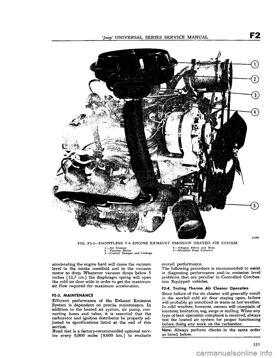
FIG.
F2-2—DAUNTLESS
V-6
ENGINE
EXHAUST
EMISSION
HEATED
AIR
SYSTEM
1—
Air
Cleaner 4—Adapter
Elbow
and Hose
2—
Vacuum
Motor 5—Manifold Heat Collector
3—
Control
Damper and
Linkage
accelerating the
engine
hard
will
cause the vacuum
level in the intake manifold and in the vacuum motor to drop. Whenever vacuum drops
below
5 inches [12,7 cm.] the diaphragm spring
will
open
the cold air door wide in order to get the maximum
air
flow required for maximum acceleration.
F2-3.
MAINTENANCE
Efficient
performance of the
Exhaust
Emission
System is
dependent
on precise maintenance. In
addition to the heated air system, air pump, con necting
hoses
and tubes, it is essential that the
carburetor
and ignition distributor be properly ad
justed to specifications listed at the end of this section.
Road
test
is a factory-recommended optional serv
ice every
6,000
miles
[9,600
km.] to evaluate
overall
performance.
The
following procedure is recommended to assist
in
diagnosing performance and/or emission level problems that are peculiar to Controlled Combus
tion Equipped vehicles.
F2-4.
Testing Thermo
Air
Cleaner Operation
Since
failure of the air cleaner
will
generally result
in
the snorkel cold air door staying open, failure
will
probably go unnoticed in warm or hot weather.
In
cold weather, however, owners
will
complain of
leanness, hesitation, sag, surge or stalling. When any
type
of lean operation complaint is received, always
test
the heated air system for proper functioning
before
doing any work on the carburetor.
Note:
Always perform checks in the same order
as listed
below.
151
Page 156 of 376
F2
EXHAUST EMISSION CONTROL SYSTEMS
the throttle
stop
screw to idle the
engine
at 650
to 700 rpm.
F2-17. Carburetor Idle Setting
The
"Lean
Best
Idle"
Method of Idle Setting is as
follows:
a.
Any scheduled service of ignition system should
precede this adjustment
b.
Connect tachometer to engine.
c.
Warm
up
engine
and stabilize temperatures.
d.
Adjust
engine
idle to speed desired, using throt
tle idle speed adjusting screw.
e.
Turn
idle mixture screws out (counterclockwise)
until
a
loss
of
engine
speed is indicated; then slowly
turn
mixture screws in (clockwise-leaner)
until
maximum speed (rpm) is reached. Continue
turning
in (clockwise) until speed begins to drop;
turn
mixture adjustment back out (counterclock
wise-richer)
until maximum speed is just regained
at
a "lean as possible" mixture adjustment.
F2-18. Distributor
The
ignition distributor used with the
Exhaust
Emission
Control
System is the same as that used
on
engines
without
Exhaust
Emission
Control.
Check
the distributor cam dwell angle and point
condition.
Check
ignition timing and adjust to specifications shown on the last
page
of this section.
F2-19.
Anti-Backfire
Valve
The
anti-backfire valve remains closed except when
the throttle is closed rapidly from an open position.
To
check the valve for proper operation, accelerate
the
engine
in neutral, allowing the throttle to close
rapidly.
The valve is operating satisfactorily when
no exhaust system backfire occurs. A further check
to determine whether the valve is functioning can
be made by removing from the anti-backfire valve
the large
hose
which connects the valve to the
pump.
With
a finger placed over the open end of
the
hose
(not the valve), accelerate the
engine
and allow the throttle to close rapidly. The valve is
operating satisfactorily if a momentary air rushing
noise is audible.
F2-20.
Check
Valve
The
check valves in the lines to the air distribution manifolds prevent the reverse flow of exhaust
gases
to the pump in the event the pump should, for
any
reason,
become
inoperative or should exhaust
pressure
ever exceed pump pressure.
To
check this valve for proper operation, remove the air supply
hose
from the pump at the check
valve.
With
the
engine
running, listen for exhaust
leakage at the check valve which is connected to
the distribution manifold.
F2-21.
Air
Pump
Check
for proper drive belt tension with belt tension
gauge
W-283. The belt strand tension should be 60 pounds measured on the
longest
accessible span
between two pulleys. DO NOT PRY ON THE
DIE
CAST
PUMP
HOUSING. To
check the pump for proper operation, remove
the air
outlet
hose
at the pump.
With
the
engine
running,
air discharge should be felt at one of
the pump
outlet
openings. The pump
outlet
air
pressure,
as determined by the relief valve, is preset
and
is not adjustable.
The
air pump
rear
cover assembly, housing the pressed in inlet and discharge tubes, and the pres
sure
relief valve are the only pump components
recommended for service replacement. These parts
are
to be replaced only when damaged as a result
of handling or in the event the relief valve was
tampered with.
F2-22.
Intake Manifold
Intake
manifold leaks must not be overlooked. Air
leakage at the intake manifold may be compen
sated for by
richer
idle mixture setting, however, this
will
usually cause uneven fuel-air distribution
and
will
always result in
loss
of performance and
exhaust emission control. To check for air leakage
into the intake manifold, apply kerosene or naph
tha,
on the intake manifold to cylinder head joints
and
observe whether any changes in
engine
rpm
occur.
If an air leak is indicated, check the mani
fold to cylinder head bolt torque. The correct torque is 25-35 lbs. ft. [3,46 a 4,84 kg-m.]. If the
leak
is
still
evident,
loosen
the manifold assembly
and
torque-tighten the bolts evenly.
Start
from the center and use proper torque values. Replace the
manifold
gasket if the leak
still
exists.
Clean
both
mating surfaces and check for
burrs
or other ir
regularities.
Always
torque the bolts evenly to the specified
torque value to prevent warpage.
F2-23.
Carburetor
Air
Cleaner
—Oil
Bath
Every
6,000
miles [9,600 km.] disconnect attach
ing
hoses
and unscrew the wing nut from the top
of the air cleaner and lift it off the carburetor.
Lift
the cover and filter element off the oil sump.
Clean
the inside surface of the sump and
refill
to
indicated
oil level with SAE 40 or 50
engine
oil
above 32 F; SAE 20 below 32 F.
Wash
filter element in kerosene and
drain.
Reassemble the air
cleaner
and install on carburetor.
More
frequent cleaning and replacement are advis able when the car is operated in dusty areas or on
unpaved
roads. Accumulated
dirt
restricts air flow,
reducing
fuel economy and performance.
F2-24.
REMOVAL PROCEDURES
The
following paragraphs
give
the procedures for removing the major units of the exhaust emission
control
system and the required equipment needed.
F2-2S.
Air
Pump
Loosen
the air pump mounting bracket bolts. Re move the air pump air hose(s). Separate the air pump from its mounting bracket. At time of install
ation,
torque tighten the air pump mounting bolts
to
30-40
lbs.-ft [4,15 a 5,53 kg-m.].
Adjust
the
belt strand tension to 60 pounds. 156
Page 157 of 376
'Jeep'
UNIVERSAL
SERIES SERVICE
MANUAL
F2
F2-26.
Anti-Backfire
Valve
The
anti-backfire valve removal requires discon necting the
hoses
and bracket to
engine
attaching
screws.
F2-27.
Air Distribution Manifold and
Injection
Tubes
The
air distribution manifolds can be removed
from the cylinder heads without removing the
cylinder
head assemblies. Disconnect the air delivery
hose
from the pump at
the distribution manifold inlet (check valve).
Loosen the distribution manifold
tube
attaching nuts from the cylinder head and carefully work the
distribution manifold away from the cylinder head.
The
air injection
tubes
can be removed from the
cylinder
head with head on the
engine.
Insert
an easy-out through the
boss
opening on the
cylinder
head
into
the injection
tube
and twist
the
tube
out gradually. Some interference to re moval may be encountered due to normal carbon
build-up on the tubes. Injection
tubes
removed in
this manner should be replaced.
The
injection
tubes
used are all of the same diam
eter and length.
F2-28.
REQUIRED EQUIPMENT
Each
station licensed to perform repair and main tenance on the Exhaust Emission Control System
must be equipped with that equipment necessary
for major
engine
tune-up analysis which shall in clude at least the following or equivalent:
Ignition Analyzer Oscilloscope
Ammeter
Ohmmeter
Voltmeter
Tachometer 2 Vacuum Gauges
Pressure
Gauge (0-10 psi.)
Cam
Angle Dwell Meter
Ignition Timing
Light
Engine
Exhaust Combustion Analyzer Compression Tester
F2-29.
REPLACEMENT PARTS
Parts
necessary to repair and/or maintain the Ex
haust Emission Control System are available through any Jeep
SALES
CORPORATION
ware
house.
F2-30.
WARRANTY
All
parts of the Exhaust Emission Control System
are
covered by the Manufacturer's
Warranty
as stated in the
Warranty
Service and 'Jeep' Quality
Maintenance Plan booklet. 157
Page 159 of 376
'Jeep'
UNIVERSAL SERIES SERVICE
MANUAL
F2
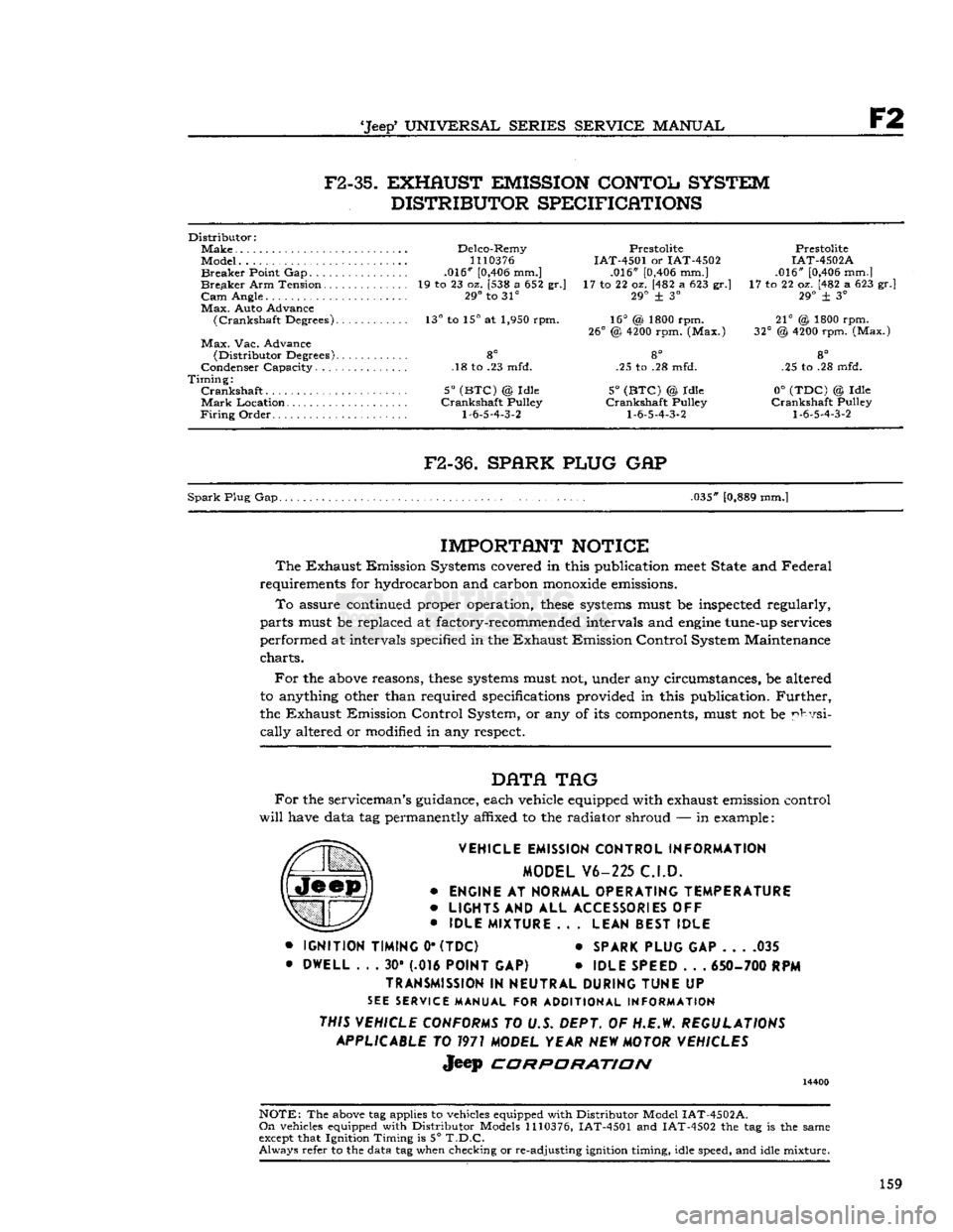
F2-35.
EXHAUST EMISSION CONTOL SYSTEM
DISTRIBUTOR SPECIFICATIONS
Distributor:
Make
Delco-Remy Prestolite Prestolite
Model...
1110376
IAT-4501 or IAT-4502 IAT-4502A
Breaker
Point Gap .016"
[0,406
mm.] .016"
[0,406
mm.] .016"
[0,406
mm.]
Breaker
Arm Tension 19 to 23 oz. [538 a 652 gr.] 17 to 22 oz. [482 a 623 gr.] 17 to 22 oz. [482 a 623 gr.]
Cam
Angle. 29° to 31° 29° + 3° 29° ± 3°
Max.
Auto Advance
(Crankshaft
Degrees). 13° to 15° at 1,950 rpm. 16° (& 1800 rpm. 21° @ 1800 rpm.
26°
@
4200
rpm. (Max.) 32° @
4200
rpm. (Max.)
Max.
Vac. Advance
(Distributor
Degrees) 8° 8° 8°
Condenser Capacity. .18 to .23 mfd. .25 to .28 mfd. .25 to .28 mfd.
Timing:
Crankshaft
5°
(BTC)
@ Idle 5°
(BTC)
© Idle 0°
(TDC)
© Idle
Mark
Location Crankshaft Pulley Crankshaft Pulley Crankshaft Pulley
Firing
Order
1-6-5-4-3-2 1-6-5-4-3-2 1-6-5-4-3-2
F2-36.
SPARK PLUG
GAP
Spark
Plug Gap. .035"
[0,889
mm.]
IMPORTANT
NOTICE
The
Exhaust Emission Systems covered in this publication
meet
State and Federal
requirements for hydrocarbon and carbon
monoxide
emissions.
To
assure continued proper operation,
these
systems
must be inspected regularly,
parts must be replaced at factory-recommended intervals and
engine
tune-up services
performed at intervals specified in the Exhaust Emission Control System Maintenance
charts.
For
the
above
reasons,
these
systems
must not, under any circumstances, be altered
to anything other than required specifications provided in this publication.
Further,
the Exhaust Emission Control System, or any of its components, must not be physi
cally
altered or modified in any respect.
DATA
TAG
For
the serviceman's guidance, each vehicle equipped with exhaust emission control
will
have data tag permanently affixed to the radiator shroud — in example:
VEHICLE EMISSION CONTROL INFORMATION MODEL V6-225 C.I.D.
•
ENGINE
AT
NORMAL OPERATING TEMPERATURE
•
LIGHTS
AND ALL
ACCESSORIES
OFF
•
IDLE MIXTURE
.. .
LEAN BEST IDLE
•
IGNITION TIMING
0*
(TDC)
*
SPARK PLUG
GAP 035
•
DWELL
. . . 30* (.016
POINT
GAP) •
IDLE SPEED
. . .
650- 700
RPM
TRANSMISSION
IN
NEUTRAL DURING TUNE
UP
SEE
SERVICE MANUAL FOR ADDITIONAL INFORMATION
THIS VEHICLE CONFORMS
TO U.S. DEPT. OF H.E.W.
REGULATIONS APPLICABLE
TO
1971
MODEL YEAR
NEW
MOTOR VEHICLES
Jeep
CORPORATION
14400
NOTE:
The
above
tag applies to vehicles equipped with Distributor Model
IAT-4502A.
On
vehicles equipped with Distributor Models
1110376,
IAT-4501 and IAT-4502 the tag is the same
except
that Ignition Timing is 5°
T.D.C.
Always
refer to the data tag when checking or re-adjusting ignition timing, idle speed, and idle mixture.
159
Page 170 of 376
G
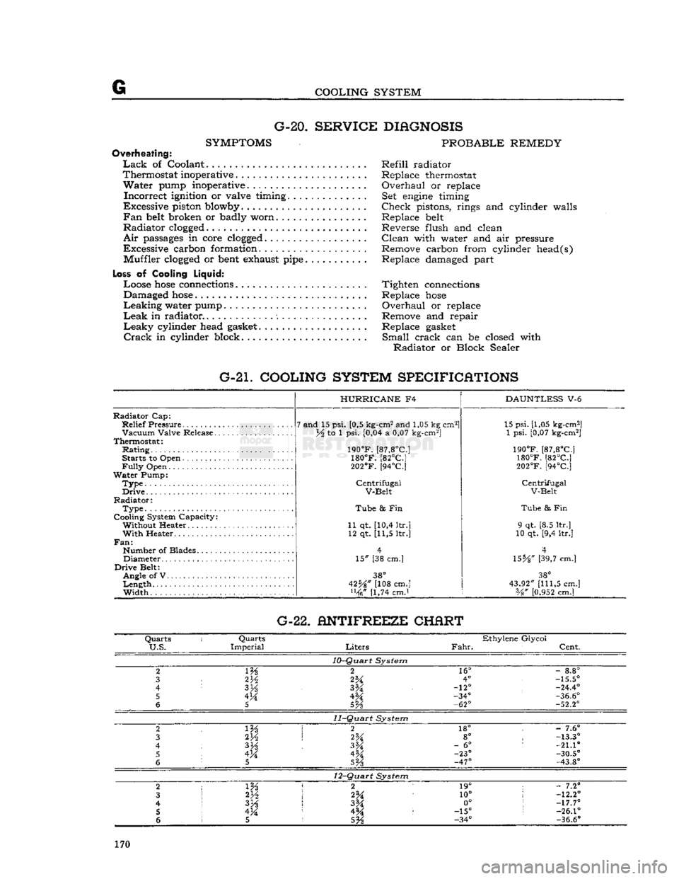
COOLING SYSTEM G-20.
SERVICE DIAGNOSIS
SYMPTOMS
PROBABLE REMEDY
Overheating:
Lack
of Coolant Refill radiator
Thermostat inoperative . Replace thermostat
Water
pump inoperative. Overhaul or replace
Incorrect
ignition or valve timing. Set
engine
timing
Excessive piston blowby Check pistons, rings and cylinder walls
Fan
belt
broken or badly worn Replace
belt
Radiator
clogged
Reverse flush and clean
Air
passages
in core
clogged
Clean with water and air pressure
Excessive carbon formation. Remove carbon from cylinder head(s) Muffler
clogged
or
bent
exhaust
pipe
Replace damaged part
Loss
of Cooling
Liquid:
Loose
hose
connections
Tighten
connections
Damaged
hose
Replace
hose
Leaking
water pump Overhaul or replace
Leak
in radiator Remove and repair
Leaky
cylinder head
gasket
Replace
gasket
Crack
in cylinder block. Small crack can be closed with
Radiator
or Block Sealer
G-21. COOLING SYSTEM SPECIFICATIONS
Radiator
Cap:
Relief
Pressure
Vacuum
Valve Release.
Thermostat:
Rating
Starts to Open
Fully
Open
Water
Pump:
Type.
Drive
Radiator:
Type
Cooling System Capacity: Without Heater
With
Heater..
Fan:
Number of Blades Diameter
Drive
Belt: Angle of V
Length
Width
HURRICANE
F4
7 and 15 psi. [0,5 kg-cm2 and 1,05 kg cm2]
lA to 1 psi. [0,04 a 0,07 kg-cm2]
190°F.
[87,8°C]
180°F.
[82°C]
202°F.
[94°C]
Centrifugal
V-Belt
Tube
8s Fin
11 qt. [10,4 ltr.] 12 qt. [11,5 ltr.]
15" [38 cm.]
38°
42%" [108 cm.] [1,74 cmJ
DAUNTLESS
V-6 15 psi. [1,05 kg-cm2]
1 psi. [0,07 kg-cm2]
190°F.
[87,8°C]
180°F.
[82°C]
202°F.
[94°C]
Centrifugal
V-Belt
Tube
& Fin
9 qt. [8.5 ltr.]
10 qt. [9,4 ltr.]
4
\SbA"
[39,7 cm.]
38°
43.92"
[111,5
cm.] Vg"
[0.952
cm.] G-22. ANTIFREEZE CHERT
Quarts
i
Quarts
Ethylene Glycol
U.S.
Imperial
Liters
Fahr.
Cent.
10-Quart
System
2
m
2
16°
-
8.8°
3
2V2
2%
4°
-15.5°
4
3H
-12°
-24.4°
5 4M -34°
-36.6°
6
5
5Vs
-62°
-52.2°
11-Quart
System
2 2
18° -
7.6°
3 2H
2%
8°
-13.3°
4
3%
-
6°
:
-21.10
5 4M 4M -23°
-30.5°
6
5
SVs
-47°
-43.8°
12-Quart
System
2
1 m 2 1
19° ;
- 7.2°
3
2*A
10°
!
-12.2°
4
I
3H
3M 0°
;
-17.7°
5 !
4M 4^ :
-15°
s
-26.1°
6 1 5
5%
-34°
-36.6°
170
Page 171 of 376
'Jeep'
UNIVERSAL SERIES SERVICE
MANUAL
H
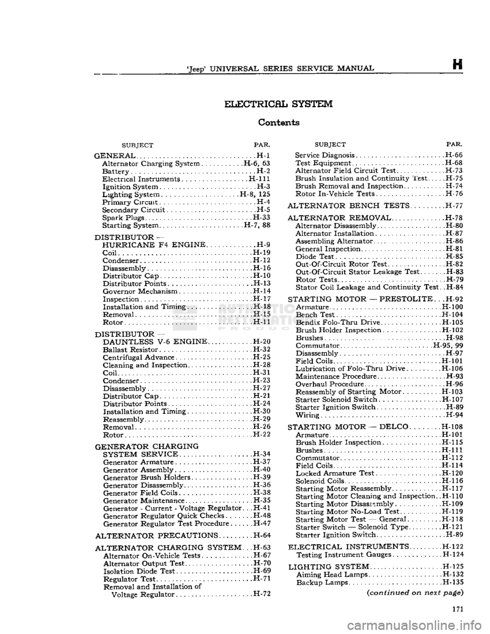
ELECTRICAL
SYSTEM
Contents
SUBJECT
PAR.
GENERAL
. -H-l Alternator Charging System H-6, 63 Battery. . . .H-2
Electrical
Instruments. H-l 11 Ignition System H-3
Lighting
System H-8, 125
Primary
Circuit.
.. H-4 Secondary
Circuit
H-5
SparkPlugs H-33
Starting System H-7, 88
DISTRIBUTOR
—
HURRICANE
F4
ENGINE
H-9
Coil
H-19 Condenser
.H-l
2
Disassembly.
.........................
.H-16
Distributor Cap H-10 Distributor
Points
H-13
Governor Mechanism H-l4
Inspection H-l
7
Installation and Timing H-18
Removal H-15
Rotor H-ll
DISTRIBUTOR
—
DAUNTLESS
V-6
ENGINE
H-20
Ballast
Resistor. H-32
Centrifugal
Advance H-25
Cleaning and Inspection H-28
Coil
H-31
Condenser H-23
Disassembly. H-27
Distributor Cap H-21 Distributor
Points
H-24
Installation and Timing. . .H-30
Reassembly. H-29
Removal H-2 6
Rotor H-2
2
GENERATOR CHARGING SYSTEM SERVICE
H-34 Generator Armature H-3
7
Generator Assembly. H-40
Generator
Brush
Holders H-39
Generator Disassembly H-36
Generator
Field
Coils.
H-38
Generator Maintenance H-35 Generator -
Current
-
Voltage
Regulator. . .H-41
Generator Regulator Quick Checks...... .H-48
Generator Regulator Test Procedure H-47
ALTERNATOR PRECAUTIONS.
H-64
ALTERNATOR CHARGING SYSTEM.
. .H-63 Alternator On-Vehicle Tests. .H-67
Alternator Output Test. .H-70 Isolation
Diode
Test H-69
Regulator Test .H-71 Removal and Installation of
Voltage
Regulator. H-72
SUBJECT
PAR.
Service
Diagnosis
H-66 Test Equipment H-68
Alternator
Field
Circuit
Test H-73
Brush
Insulation and Continuity Test H-75
Brush
Removal and Inspection H-74
Rotor In-Vehicle Tests H-76
ALTERNATOR BENCH TESTS.
.H-77
ALTERNATOR REMOVAL
H-78 Alternator Disassembly H-80 Alternator Installation. H-87
Assembling Alternator H-86
General
Inspection H-81
Diode
Test H-85
Out-Of-Circuit
Rotor Test. .H-82
Out-Of-Circuit
Stator Leakage Test.. . H-83 Rotor Tests H-79
Stator
Coil
Leakage and Continuity Test. .H-84
STARTING
MOTOR
—
PRESTOLITE.
. .H-92
Armature
.H-l
00 Bench Test H-l04
Bendix
Folo-Thru
Drive H-105
Brush
Holder Inspection. .H-102
Brushes H-98
Commutator H-95, 99
Disassembly H-9 7
Field
Coils H-101
Lubrication
of
Folo-Thru
Drive H-l06
Maintenance Procedure H-93
Overhaul
Procedure H-96
Reassembly of Starting Motor. .
H-l
03
Starter
Solenoid
Switch H-10 7 Starter Ignition Switch. .H-89
Wiring.
. . . H-94
STARTING
MOTOR
—DELCO
H-108
Armature
H-101
Brush
Holder Inspection H-l 15 Brushes
H:lll
Commutator H-112
Field
Coils........
H-114
Locked
Armature Test. . . H-l20
Solenoid
Coils H-l 16
Starting Motor Reassembly H-l 17
Starting Motor Cleaning and Inspection.
.H-l
10
Starting Motor Disassembly .H-109 Starting Motor No-Load Test H-119
Starting Motor Test — General H-l 18 Starter Switch —
Solenoid
Type. H-l21
Starter Ignition Switch. .H-89
ELECTRICAL
INSTRUMENTS
H-122 Testing Instrument Gauges H-l24
LIGHTING
SYSTEM
H-l25 Aiming Head Lamps H-132
Backup
Lamps H-135
(continued
on
next
page)
171
Page 172 of 376
H
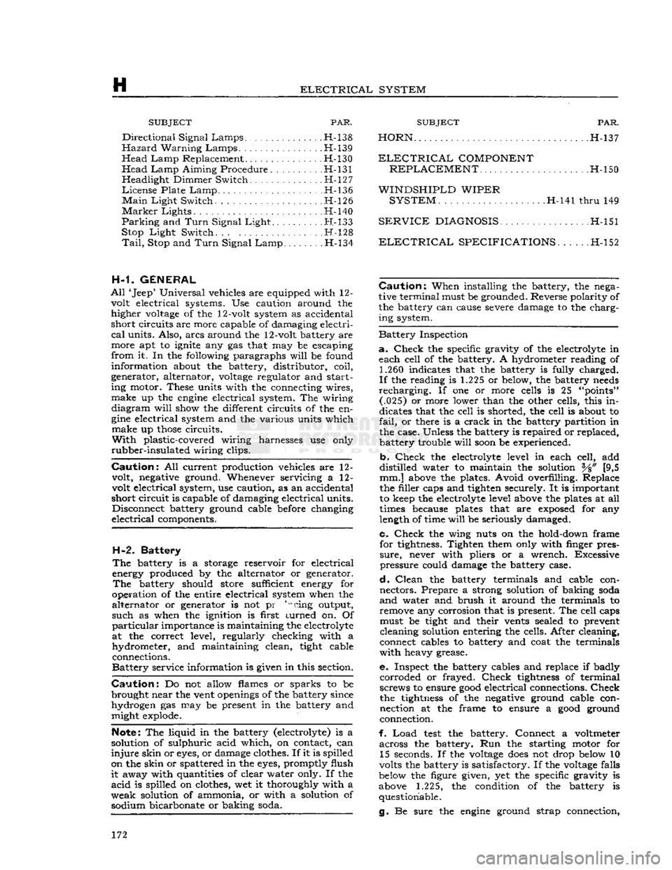
ELECTRICAL
SYSTEM SUBJECT
PAR.
Directional
Signal
Lamps
H-138
Hazard
Warning
Lamps
H-139
Head
Lamp
Replacement H-130
Head
Lamp
Aiming Procedure H-131 Headlight Dimmer Switch H-127
License
Plate
Lamp
H-136
Main
Light
Switch. H-126
Marker
Lights .H-l40
Parking
and
Turn
Signal
Light
H-133
Stop
Light
Switch. H-l28
Tail,
Stop and
Turn
Signal
Lamp
.H-134
H-1. GENERAL
All
'Jeep' Universal vehicles are equipped with 12- volt electrical systems. Use caution around the higher
voltage
of the 12-volt system as accidental
short
circuits are more capable of damaging electri
cal
units. Also, arcs around the 12-volt battery are
more apt to ignite any gas that may be escaping
from
it. In the following paragraphs
will
be found
information about the battery, distributor, coil,
generator, alternator,
voltage
regulator and start ing motor. These units with the connecting wires,
make
up the
engine
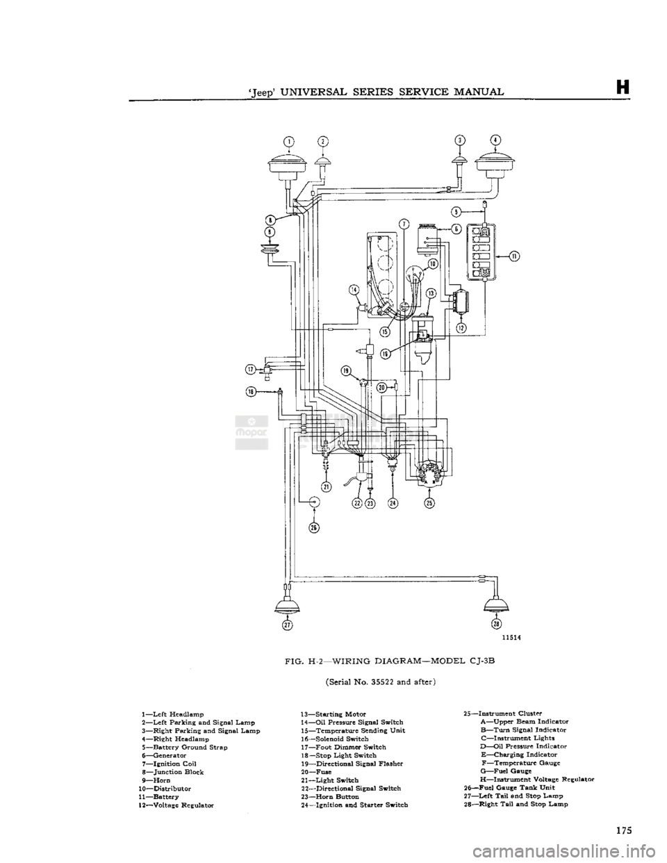
electrical system. The wiring
diagram
will
show the different circuits of the en
gine
electrical system and the various units which
make
up
those
circuits.
With
plastic-covered wiring harnesses use only
rubber-insulated
wiring clips.
Caution:
All current production vehicles are 12- volt, negative ground. Whenever servicing a 12-
volt electrical system, use caution, as an accidental
short
circuit is capable of damaging electrical units. Disconnect battery ground cable before changing
electrical
components.
H-2.
Battery
The
battery is a storage reservoir for electrical
energy produced by the alternator or generator.
The
battery should store sufficient energy for
operation of the entire electrical system when the
alternator
or generator is not pr 1,scing output,
such
as when the ignition is first turned on. Of
particular
importance is maintaining the electrolyte
at the correct level, regularly checking with a
hydrometer, and maintaining clean, tight cable connections.
Battery
service information is given in this section.
Caution:
Do not allow flames or sparks to be
brought near the vent
openings
of the battery since
hydrogen gas may be present in the battery and might explode.
Note:
The liquid in the battery (electrolyte) is a
solution of sulphuric acid which, on contact, can
injure
skin or
eyes,
or damage clothes. If it is spilled
on the skin or spattered in the
eyes,
promptly flush
it
away with quantities of clear water only. If the
acid
is spilled on clothes, wet it thoroughly with a
weak
solution of ammonia, or with a solution of sodium bicarbonate or baking soda.
SUBJECT
PAR.
HORN
H-137
ELECTRICAL
COMPONENT
REPLACEMENT
H-150
WINDSHIPLD
WIPER SYSTEM
H-141
thru
149
SERVICE
DIAGNOSIS.
. .H-151
ELECTRICAL
SPECIFICATIONS
H-152
Caution:
When installing the battery, the nega
tive terminal must be grounded. Reverse polarity of the battery can cause severe damage to the charging system.
Battery
Inspection
a.
Check
the specific gravity of the electrolyte in
each cell of the battery. A hydrometer reading of 1.260 indicates that the battery is fully charged.
If
the reading is 1.225 or below, the battery
needs
recharging.
If one or more cells is 25 "points" (.025) or more lower than the other cells, this in
dicates that the cell is shorted, the cell is about to
fail,
or there is a
crack
in the battery partition in
the case. Unless the battery is repaired or replaced, battery trouble
will
soon
be experienced.
b.
Check
the electrolyte level in each cell, add
distilled
water to maintain the solution [9,5 mm.] above the plates. Avoid overfilling. Replace
the filler caps and tighten securely. It is important to keep the electrolyte level above the plates at all
times because plates that are
exposed
for any
length of time
will
be seriously damaged.
c.
Check
the wing nuts on the hold-down frame for tightness. Tighten them only with finger pres
sure,
never with pliers or a wrench. Excessive
pressure
could damage the battery case.
d.
Clean
the battery terminals and cable con nectors. Prepare a strong solution of baking soda
and
water and brush it around the terminals to
remove any corrosion that is present. The cell caps must be tight and their vents sealed to prevent
cleaning solution entering the cells. After cleaning,
connect cables to battery and coat the terminals
with
heavy grease.
e.
Inspect the battery cables and replace if badly
corroded
or frayed.
Check
tightness
of terminal
screws to ensure
good
electrical connections.
Check
the
tightness
of the negative ground cable connection at the frame to ensure a
good
ground
connection.
f.
Load
test
the battery. Connect a voltmeter across the battery. Run the starting motor for 15 seconds. If the
voltage
does
not drop below 10
volts the battery is satisfactory. If the
voltage
falls
below the figure given, yet the specific gravity is
above
1.225,
the condition of the battery is questionable.
g. Be sure the
engine
ground strap connection, 172
Page 173 of 376
'Jeep'
UNIVERSAL
SERIES
SERVICE
MANUAL
H
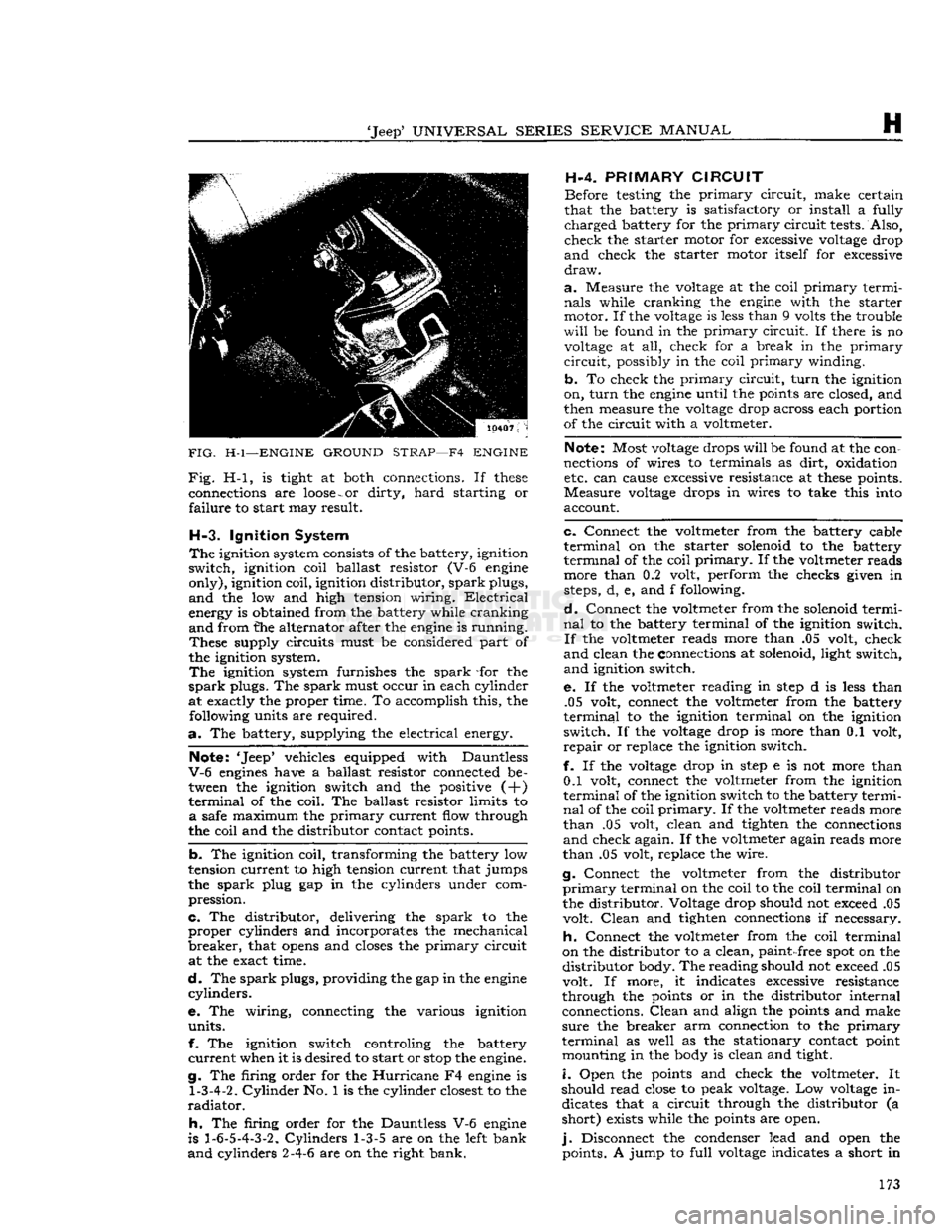
FIG.
H-l—ENGINE
GROUND
STRAP—F4
ENGINE
Fig.
H-l, is tight at both connections. If
these
connections are
loose
-
or
dirty,
hard
starting or
failure
to start may result.
H-3.
Ignition System
The
ignition system consists of the battery, ignition
switch,
ignition coil ballast resistor (V-6 engine
only),
ignition coil, ignition distributor,
spark
plugs,
and
the low and high tension wiring.
Electrical
energy is obtained from the battery while cranking
and
from the alternator after the engine is running.
These
supply circuits must be considered part of
the ignition system.
The
ignition system furnishes the
spark
-for the
spark
plugs. The
spark
must occur in each cylinder
at exactly the proper time. To accomplish this, the following units are required.
a.
The battery, supplying the electrical energy.
Note: 'Jeep* vehicles equipped with Dauntless
V-6
engines have a ballast resistor connected be tween the ignition switch and the positive (+)
terminal
of the coil. The ballast resistor limits to
a
safe maximum the
primary
current flow through
the coil and the distributor contact points.
b.
The ignition coil, transforming the battery low
tension current to high tension current that jumps
the
spark
plug gap in the cylinders under com
pression.
c.
The distributor, delivering the
spark
to the
proper
cylinders and incorporates the mechanical
breaker,
that
opens
and closes the
primary
circuit at the exact time.
d.
The
spark
plugs, providing the gap in the engine
cylinders.
e. The wiring, connecting the various ignition
units.
f. The ignition switch controling the battery
current
when it is desired to start or
stop
the engine.
g. The firing order for the
Hurricane
F4 engine is
1-3-4-2.
Cylinder
No. 1 is the cylinder closest to the
radiator.
h.
The firing order for the Dauntless V-6 engine
is
1-6-5-4-3-2.
Cylinders
1-3-5 are on the left bank
and
cylinders 2-4-6 are on the right bank. H-4.
PRIMARY
CIRCUIT
Before testing the
primary
circuit,
make certain
that the battery is satisfactory or install a fully
charged
battery for the
primary
circuit
tests. Also,
check
the starter motor for excessive voltage drop
and
check the starter motor itself for excessive
draw.
a.
Measure the voltage at the coil
primary
termi
nals
while cranking the engine with the starter
motor. If the voltage is less than 9 volts the trouble
will
be found in the
primary
circuit.
If there is no voltage at all, check for a break in the
primary
circuit,
possibly in the coil
primary
winding.
b.
To check the
primary
circuit,
turn
the ignition
on,
turn
the engine until the points are closed, and
then measure the voltage drop across each portion
of the circuit with a voltmeter.
Note: Most voltage drops
will
be found at the con
nections of wires to terminals as
dirt,
oxidation etc. can cause excessive resistance at
these
points.
Measure
voltage drops in wires to take this into
account.
c.
Connect the voltmeter from the battery cable
terminal
on the starter solenoid to the battery
terminal
of the coil
primary.
If the voltmeter reads more than 0.2 volt, perform the checks given in
steps, d, e, and f following.
d.
Connect the voltmeter from the solenoid termi
nal
to the battery terminal of the ignition switch.
If
the voltmeter reads more than .05 volt, check
and
clean the connections at solenoid, light switch,
and
ignition switch.
e. If the voltmeter reading in
step
d is less than .05 volt, connect the voltmeter from the battery
terminal
to the ignition terminal on the ignition
switch.
If the voltage drop is more than 0.1 volt,
repair
or replace the ignition switch.
f. If the voltage drop in
step
e is not more than 0.1 volt, connect the voltmeter from the ignition
terminal
of the ignition switch to the battery termi
nal
of the coil
primary.
If the voltmeter reads more
than
.05 volt, clean and tighten the connections
and
check again. If the voltmeter again reads more
than
.05 volt, replace the wire.
g. Connect the voltmeter from the distributor
primary
terminal on the coil to the coil terminal on
the distributor. Voltage drop should not exceed .05 volt.
Clean
and tighten connections if necessary.
h.
Connect the voltmeter from the coil terminal
on the distributor to a clean,
paint-
free spot on the
distributor
body. The reading should not exceed .05
volt. If more, it indicates excessive resistance
through the points or in the distributor internal connections.
Clean
and align the points and make
sure
the breaker arm connection to the
primary
terminal
as well as the stationary contact point mounting in the body is clean and tight.
i.
Open the points and check the voltmeter. It
should read close to peak voltage. Low voltage in dicates that a circuit through the distributor (a
short)
exists while the points are open.
j.
Disconnect the condenser lead and open the points. A jump to
full
voltage indicates a short in 173
Page 174 of 376
H
ELECTRICAL
SYSTEM
the condenser. Replace the condenser. If there is
no jump to full voltage, overhaul or replace the
distributor.
k.
With the points closed, connect the voltmeter
from
a clean, paint-free
post
on the distributor
body to the negative
post
of the battery. The volt
age drop should be practically zero, a hardly
readable deflection on the voltmeter. If the volt meter registers a
voltage
drop, perform the checks
in
steps
1
and m following.
I.
Check
for
voltage
drop in the battery ground
cable.
Clean
the battery
post,
cable terminals, and contact surface on the bellhousing, or on body if
a
noticeable deflection of the voltmeter occurs,
m.
Check
for any
voltage
drop
between
the dis
tributor
body and a clean, paint-free
spot
on the
cylinder
block. If there is any
voltage
drop, remove
the distributor and clean the mounting surfaces of
distributor
body and cylinder block.
H-5.
SECONDARY
CIRCUIT
If
satisfactory ignition is not obtainable with cor
rect
point gap and tension; satisfactory condenser;
sufficient primary voltage; and correctly cleaned, gapped, and installed spark plugs; the secondary
circiut
should be investigated.
a.
Test the coil.
Bring
the coil up to operating
temperature using the coil heat feature of a coil tester, if available. Refer to the coil tester manu
facturer's
instructions for specific hook-ups for
performing the checks given in
steps
b, c, and d following.
b. Connect the positive lead of the tester to the
battery terminal of the coil primary winding.
Con
nect the tester ground lead to the coil tower. Mea
sure
the resistance of the secondary winding. If the
resistance is more than
20,000
ohms, a fault in the
secondary winding is indicated.
c.
Check
for a grounded secondary by touching the tester ground lead to the coil cover. If resistance
is not over
100,000
ohms, the secondary is grounded
to the cover.
d.
If the secondary winding is satisfactory, mea
sure
the primary current draw in accordance with
the instructions of the
test
equipment manu
facturer.
e.
Check
the secondary circuit for leakage. With the coil primary in the circuit with the breaker unit of the tester, connect a long, high-tension
test
lead
to the coil tower.
Check
the secondary circuit for
leakage by performing the checks given in
steps
f. g, h, and i following.
Note:
In the following
tests,
a slight sparking and
meter deflection
will
usually be
seen
just as contact
is made.
This
is caused by capacitance and
does
not
indicate defective insulation.
f.
Check
distributor cap. Remove the coil lead from the cap and touch the
test
lead to the center contact
inside the cap. If the meter reading drops when the contact is touched or if sparking is seen, a leakage
path is present
between
the center contact and one
of the plug towers.
This
leakage path
will
be in the
form
of a
crack
or carbon track in the cap. Discon nect the spark plug wires from the cap one at a
time and
test
each plug contact with the high-
voltage
lead and with all other plug wires con
nected. Any sparking or meter drop indicates that
a
leakage path exists
between
that particular con
tact and an adjacent one. Testing the adjacent contacts
will
determine which pair is at fault,
g-
Check
distributor rotor. Touch the
test
lead to
the spring contact in the center of the distributor
rotor.
Any leakage in the rotor insulation
between
the contact and the shaft
will
cause a drop in the meter reading and usually sparking
will
be seen.
h.
Check
spark plug wires. Disconnect the spark
plug wires from the plugs and
test
the plug terminal of each. The meter reading should not drop below
the open secondary value (value before making contact). If it
does
or if a large spark occurs when
the
test
lead and the plug wire are separated, there
is a break in the insulation on that wire.
i.
Check
the coil tower insulation. Remove the
high-tension
test
lead from the coil tower and touch
the ground lead of the coil tester to several points
around
the base of the tower. Any sparking or deflection of the meter indicates a leakage path in
the tower insulation.
H-6.
Alternator Charging System
All
Jeep
Universal
Series vehicles have, as standard
equipment a 35-amp., 12-volt, negative ground
alternator and a transistorized
voltage
regulator.
For
repairing the alternator, many of its major components are furnished as complete assemblies
including:
complete brush assembly which requires no soldering or unsoldering of leads; two complete
rectifying
diode
assemblies which eliminate the need for removing and replacing individual diodes;
a
complete isolation
diode
assembly; and a rotor assembly complete with shaft,
pole
pieces, field coil,
and
slip rings.
The
transistorized
voltage
regulator is an electronic
switching device. It
senses
the
voltage
appearing at the auxiliary terminal of the alternator and
supplies the necessary field current for maintaining the system
voltage
at the output
terminal.
The out
put current is determined by the battery electrical
load;
such as headlights, heater, etc.
The
transistorized
voltage
regulator is a sealed unit,
has no adjustments, and must be replaced as a
complete unit.
H-7.
Starting System
The
operation of the starter motor is controlled by
the ignition switch. The starter is made up of a
frame,
field coil, armature, and brushes.
The
starter solenoid electrically
closes
the circuit
between
the battery and the starter motor. When the ignition key is turned to its extreme right, the
solenoid is energized and
closes
the battery-to- starter-motor circuit.
Note:
All Jeep Universal Series vehicles have the
starter
solenoid switch secured to the starter motor
assembly. The Hurricane F4 and Dauntless V-6
engine
Prestolite starter drive is of the inertia type
(rexr
continued on
page
176) 174
Page 175 of 376
'Jeep'
UNIVERSAL
SERIES
SERVICE
MANUAL
H
11514
FIG.
H-2—WIRING
DIAGRAM—MODEL
CJ-3B
(Serial No.
35522
and
after)
1—
Left
Headlamp
2—
Left
Parking and Signal Lamp
3— Right Parking and Signal Lamp
4— Right Headlamp 5— Battery Ground Strap
6— Generator 7— Ignition
Coil
8— Junction Block
9—
Horn
10— Distributor
11— Battery
12—
Voltage
Regulator 13— Starting Motor
14—
Oil
Pressure Signal Switch 15— Temperature Sending Unit
16—
Solenoid
Switch 17— Foot Dimmer Switch
18—
Stop
Light Switch 19— Directional Signal Flasher
20— Fuse
21—
Light
Switch 22— Directional Signal Switch
23—
Horn
Button 24— Ignition and Starter Switch 25—Instrument Cluster
A—Upper Beam Indicator
B—Turn
Signal Indicator C—Instrument Lights
D—Oil
Pressure Indicator
E—Charging
Indicator F—Temperature Gauge
G—Fuel
Gauge
H—Instrument
Voltage
Regulator
25—Fuel Gauge Tank Unit
27—
Left
Tail
and
Stop
Lamp
28— Right
Tail
and
Stop
Lamp 175