ignition JEEP CJ 1953 Workshop Manual
[x] Cancel search | Manufacturer: JEEP, Model Year: 1953, Model line: CJ, Model: JEEP CJ 1953Pages: 376, PDF Size: 19.96 MB
Page 176 of 376
H
ELECTRICAL
SYSTEM
11474
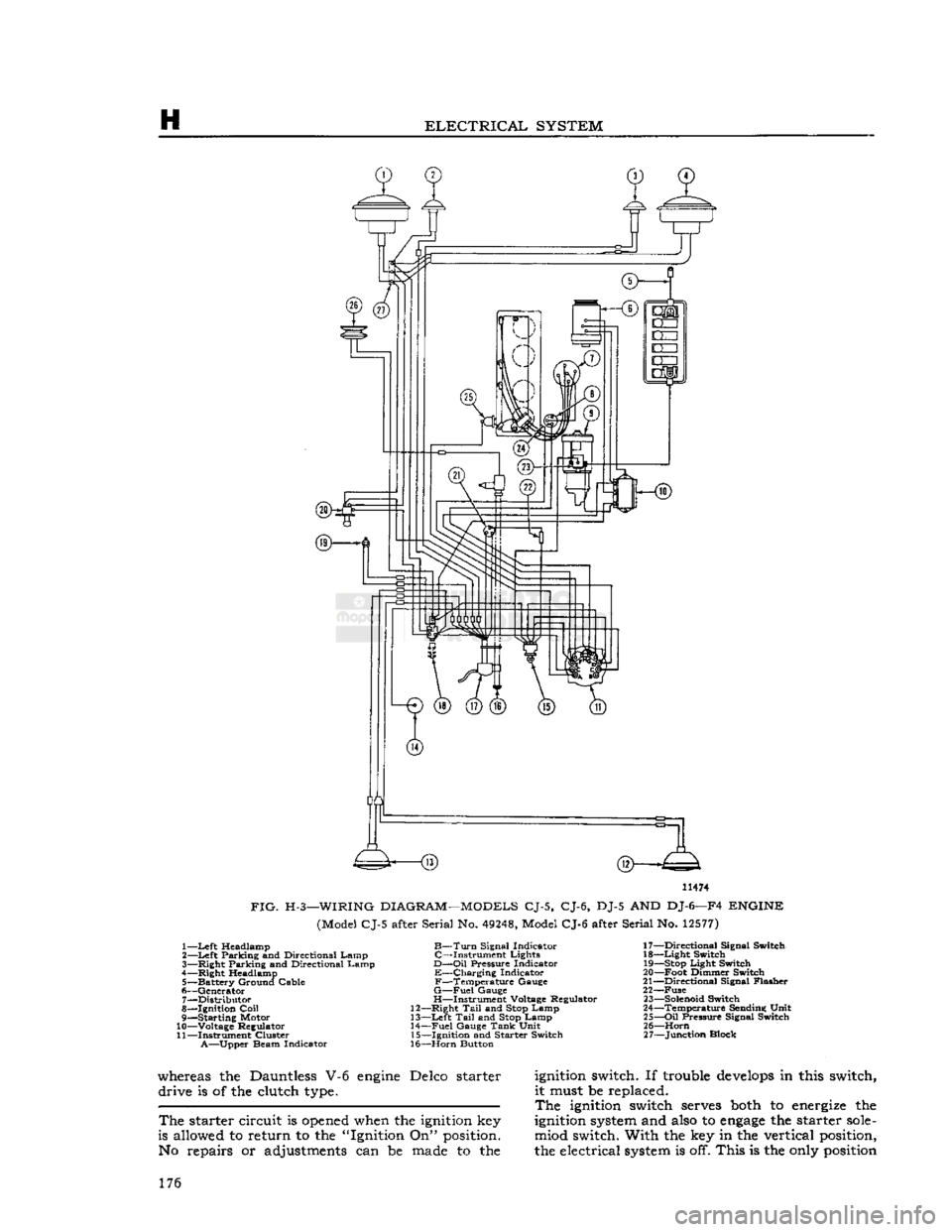
FIG.
H-3—WIRING
DIAGRAM—MODELS
CJ-5, CJ-6, DJ-5 AND DJ-6—F4
ENGINE
(Model CJ-5 after Serial No.
49248,
Model CJ-6 after Serial No.
12577)
1—
Left
Headlamp
B—Turn
Signal Indicator 17—Directional Signal Switch
2—
Left
Parking and Directional Lamp C—Instrument Lights 18—Light Switch
3— Right Parking and Directional Lamp
D—Oil
Pressure Indicator
19—Stop
Light Switch
4— Right Headlamp E—Charging Indicator 20—Foot Dimmer Switch
5— Battery Ground Cable F—Temperature Gauge 21—Directional Signal Flasher
6— Generator
G—Fuel
Gauge 22—Fuse 7— Distributor H—Instrument Voltage Regulator
23—Solenoid
Switch
8— Ignition
Coil
12—Right
Tail
and
Stop
Lamp 24—Temperature Sending Unit
9— Starting Motor 13—Left
Tail
and
Stop
Lamp 25—Oil Pressure Signal Switch
10— Voltage Regulator 14—Fuel Gauge
Tank
Unit 26—Horn
11— Instrument Cluster 15—Ignition and Starter Switch 27—Junction Block
A—Upper
Beam Indicator 16—Horn Button
whereas the Dauntless V-6
engine
Delco starter
ignition
switch. If trouble
develops
in this switch, drive is of the clutch
type.
it must be replaced.
The
ignition
switch
serves
both
to
energize
the
The
starter circuit is
opened
when the
ignition
key
ignition
system
and
also
to
engage
the starter
sole-
is allowed to return to the "Ignition On"
position.
miod switch. With the key in the vertical
position,
No repairs or adjustments can be
made
to the the electrical
system
is off. This is the
only
position
176
Page 177 of 376
'Jeep*
UNIVERSAL
SERIES
SERVICE
MANUAL
H
12968
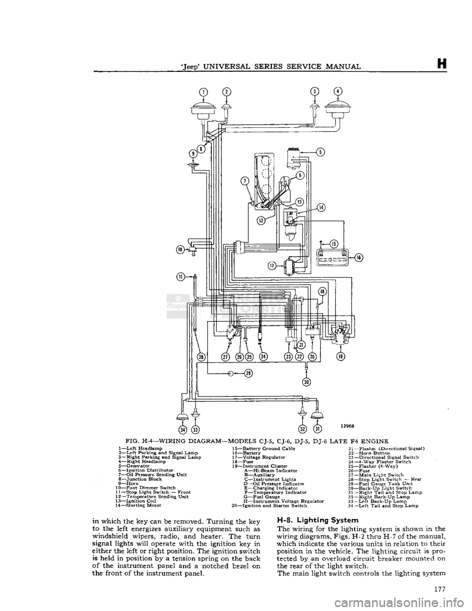
FIG.
H-4—WIRING
DIAGRAM—MODELS
CJ-5, CJ-6, DJ-5, DJ-6
LATE
F4
ENGINE
1—
Left
Headlamp
2—
Left
Parking and Signal Lamp
3— Right Parking and Signal Lamp 4— Right Headlamp
5— Generator
6— Ignition Distributor
7—
Oil
Pressure Sending Unit
8— Junction Block
9—
Horn
10— Foot Dimmer Switch 11—
Stop
Light Switch — Front
12— Temperature Sending Unit
13— Ignition
Coil
14— Starting Motor 15— Battery Ground Cable
16— Battery
17— Voltage Regulator 18—
Fuse
19— Instrument Cluster
A—Hi-Beam
Indicator
B—Auxiliary
C—Instrument
Lights
D—Oil
Pressure Indicator
E—Charging
Indicator
F—Temperature
Indicator
G—Fuel
Gauge
H—Instrument Voltage Regulator
20— Ignition and Starter Switch 21—
Flashei
(Directional Signal)
22—
Horn
Button 23— Directional Signal Switch
24— 4-Way Flasher Switch
25—
Flasher
(4-Way)
26—
Fuse
27—
Main
Light Switch 28—
Stop
Light Switch — Rear
29—
Fuel
Gauge
Tank
Unit
30—
Back-Up
Light Switch
31— Right
Tail
and
Stop
Lamp
32— Right Back-Up Lamp
33—
Left
Back-Up Lamp
34—
Left
Tail
and
Stop
Lamp
in
which the key can be removed. Turning the key
to the
left
energizes
auxiliary
equipment
such as
windshield wipers, radio, and heater. The turn
signal
lights
will
operate
with the
ignition
key in
either the
left
or right
position.
The
ignition
switch is held in
position
by a
tension
spring on the back
of the instrument panel and a
notched
bezel on
the front of the instrument panel.
H-8.
Lighting System
The
wiring for the lighting
system
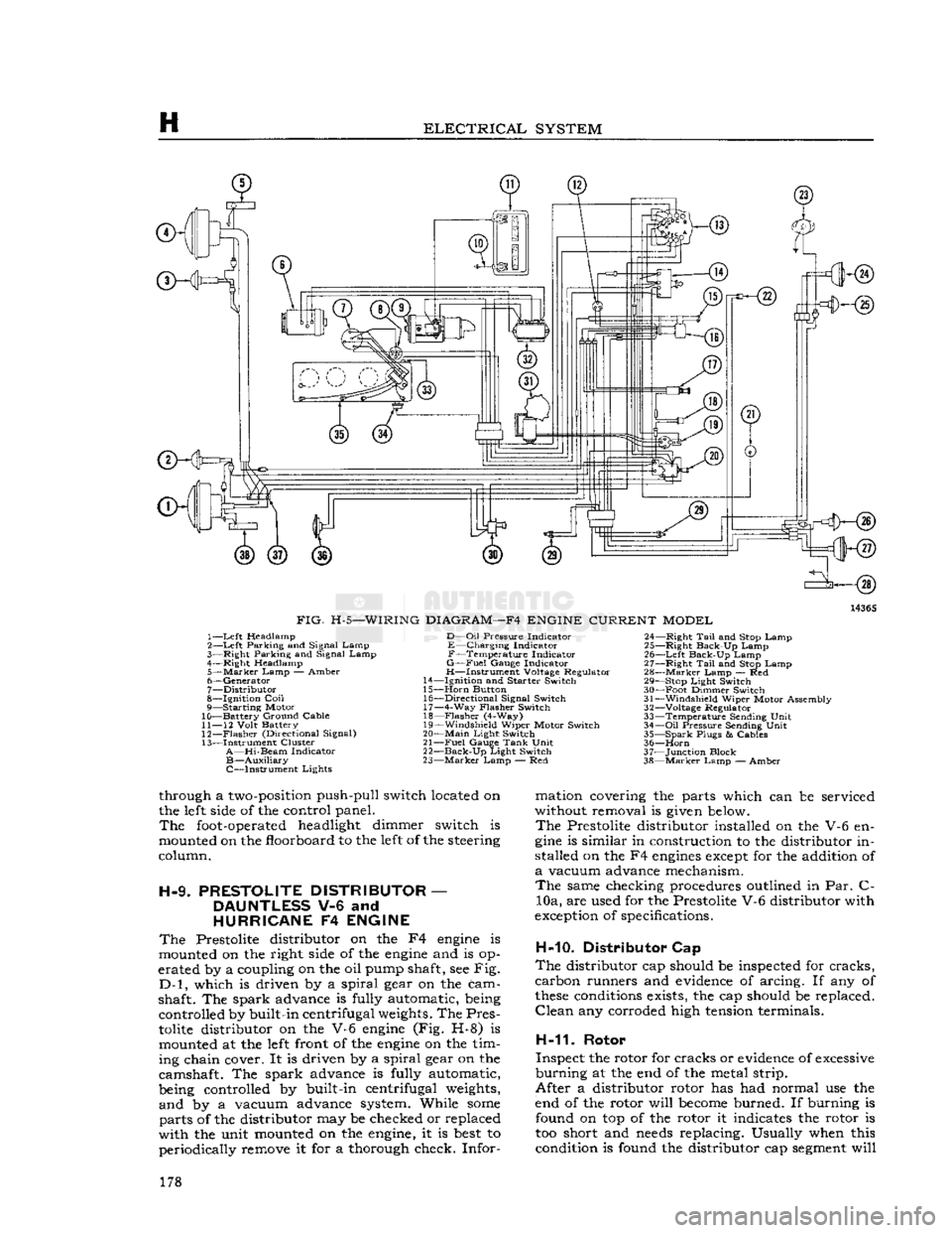
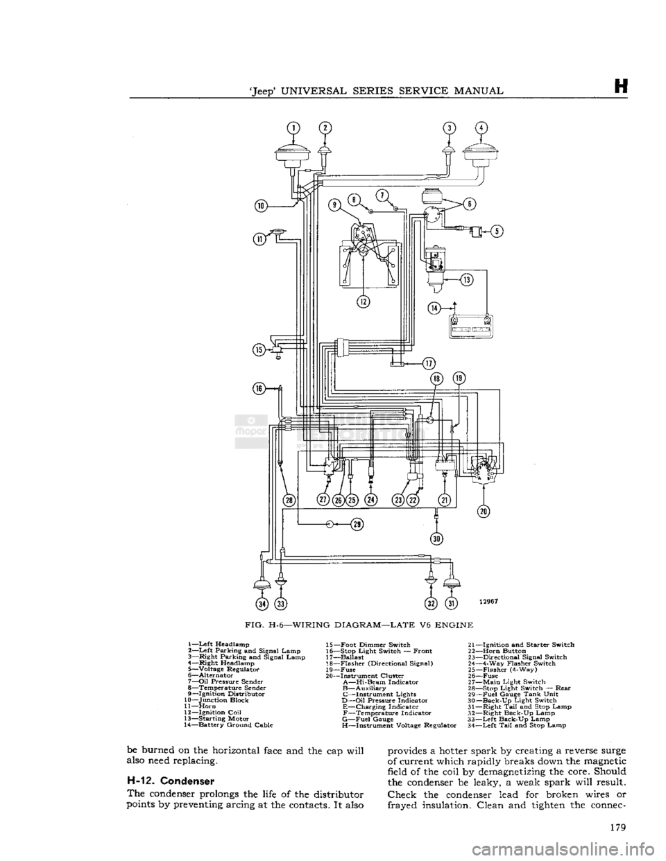
is shown in the
wiring diagrams, Figs. H-2 thru H-7 of the manual,
which indicate the various units in relation to their
position
in the vehicle. The lighting circuit is pro
tected
by an overload circuit breaker
mounted
on the rear of the light switch.
The
main light switch controls the lighting
system
177
Page 178 of 376
H
ELECTRICAL
SYSTEM
14365
FIG.
H-5—WIRING
DIAGRAM—F4
ENGINE
CURRENT
MODEL
1—
Left
Headlamp
2—
Left
Parking and Signal Lamp
3—
Right
Parking and Signal Lamp
4—
Right
Headlamp
5—
Marker
Lamp
— Amber
6—
Generator
7—
Distributor
8—
Ignition
Coil
9— Starting Motor
10— Battery Ground Cable
11—
12
Volt
Battery
12—
Flasher
(Directional Signal)
13— Instrument Cluster
A—Hi-Beam
Indicator
B—Auxiliary
C—Instrument Lights
D—Oil
Pressure
Indicator
E—Charging Indicator
F—Temperature Indicator
G—Fuel
Gauge
Indicator
H—Instrument Voltage Regulator
14—
Ignition
and
Starter
Switch
15—
Horn
Button 16—
Directional
Signal Switch 17— 4-Way
Flasher
Switch
18—
Flasher
(4-Way)
19—
Windshield
Wiper Motor Switch
20—
Main
Light
Switch
21—
Fuel
Gauge
Tank
Unit
22—
Back-Up
Light
Switch
23—
Marker
Lamp — Red 24—
Right
Tail
and Stop Lamp
25—
Right
Back-Up Lamp
26—
Left
Back-Up Lamp
27—
Right
Tail
and Stop Lamp
28—
Marker
Lamp — Red 29— Stop
Light
Switch
30— Foot Dimmer Switch
31—
Windshield
Wiper Motor Assembly
32—
Voltage Regulator
33— Temperature Sending
Unit
34—
Oil
Pressure
Sending
Unit
35— Spark
Plugs
&
Cables
36—
Horn
37— Junction Block
38—
Marker
Lamp — Amber
through a
two-position
push-pull switch located on
the
left
side
of the control panel.
The
foot-operated
headlight dimmer switch is
mounted on the floorboard to the
left
of the steering
column.
H-9.
PRESTOLITE
DISTRIBUTOR
—
DAUNTLESS
V-6 and
HURRICANE
F4
ENGINE
The
Prestolite distributor on the F4
engine
is
mounted on the right
side
of the
engine
and is op
erated by a coupling on the oil pump shaft, see Fig.
D-l,
which is driven by a spiral gear on the cam
shaft. The spark advance is fully automatic, being controlled by built-in centrifugal
weights.
The Pres
tolite
distributor on the V-6
engine
(Fig. H-8) is mounted at the
left
front of the
engine
on the tim
ing chain cover. It is driven by a spiral gear on the
camshaft. The spark advance is fully automatic,
being controlled by built-in centrifugal
weights,
and by a vacuum advance system. While
some
parts of the distributor may be checked or replaced
with the unit mounted on the
engine,
it is
best
to periodically remove it for a thorough check. Infor mation covering the parts which can be serviced
without removal is
given
below.
The
Prestolite distributor installed on the V-6 en
gine
is similar in construction to the distributor in
stalled on the F4
engines
except
for the addition of
a
vacuum advance mechanism.
The
same checking procedures outlined in Par. C- 10a, are used for the Prestolite V-6 distributor with
exception
of specifications.
H-10. Distributor Cap
The
distributor cap should be inspected for cracks,
carbon runners and
evidence
of arcing. If any of
these
conditions
exists, the cap should be replaced.
Clean
any corroded high
tension
terminals.
H-11.
Rotor
Inspect the rotor for cracks or
evidence
of
excessive
burning at the end of the metal strip.
After a distributor rotor has had normal use the
end of the rotor will
become
burned. If burning is found on top of the rotor it indicates the rotor is
too short and
needs
replacing. Usually when this condition is found the distributor cap
segment
will 178
Page 179 of 376
'Jeep'
UNIVERSAL
SERIES
SERVICE
MANUAL
H
12967
FIG.
H-6—WIRING
DIAGRAM—LATE
V6
ENGINE
1—Left Headlamp
2—
Left
Parking and Signal Lamp
3—
Right
Parking and Signal Lamp
4—
Right
Headlamp
5— Voltage Regulator
6—
Alternator
7—
Oil
Pressure
Sender
8— Temperature
Sender
9—
Ignition
Distributor
10— Junction Block
11—
Horn
12—
Ignition
Coil
13— Starting Motor
14— Battery Ground Cable 15— Foot Dimmer Switch 21-
16— Stop
Light
Switch — Front 22-
17— Ballast 23-
18—
Flasher
(Directional Signal) 24-
19—
Fuse
25-
20— Instrument Cluster 26-
A—Hi-Beam
Indicator 27-
B—Auxiliary
28- C—Instrument Lights 29-
D—Oil
Pressure
Indicator 30-
E—Charging Indicator 31-F—Temperature Indicator 32-
G—Fuel
Gauge
33-
H—Instrument Voltage Regulator 34-
-Ignition
and
Starter
Switch
-Horn
Button
-Directional
Signal Switch
-4-Way
Flasher
Switch
-Flasher
(4-Way)
-Fuse
-Main
Light
Switch
-Stop
Light
Switch —
Rear
-Fuel
Gauge
Tank
Unit
-Back-Up
Light
Switch
-Right
Tail
and Stop Lamp
-Right
Back-Up Lamp
-Left
Back-Up Lamp
-Left
Tail
and Stop Lamp
be burned on the horizontal
face
and the cap will
also
need
replacing. H-12. Condenser
The
condenser
prolongs
the
life
of the distributor
points
by
preventing
arcing at the
contacts.
It
also
provides
a
hotter
spark by creating a reverse
surge
of current which rapidly breaks
down
the
magnetic
field of the coil by
demagnetizing
the core. Should
the
condenser
be leaky, a weak spark will result.
Check
the
condenser
lead for broken wires or
frayed insulation. Clean and
tighten
the
connec-
179
Page 180 of 376
H
ELECTRICAL
SYSTEM
ffKHs)
3—<§)
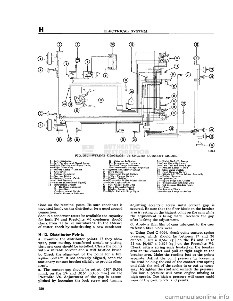
FIG.
H-7—WIRING
DIAGRAM—V6
ENGINE
CURRENT
MODEL
1—
Left
Headlamp
2—Left Parking and Signal Lamp
3— Right Parking and Signal Lamp
4—Right Headlamp 5—
Marker
Lamp — Amber
6— Alternator 7— Voltage Regulator
8— Starting Motor
9— Battery Ground Cable
10— 12 Volt Battery
11—
Flasher
(Directional Signal)
12— Instrument Cluster
A—Hi-Beam
Indicator
B—Auxiliary
C—Instrument
Lights
D—Oil
Pressure Indicator
E—Charging
Indicator
F—Temperature
Indicator
G—Fuel
Gauge Indicator
H—Instrument Voltage Regulator
13— Ignition and Starter Switch
14—
Horn
Button
15— Directional Signal Switch
16— 4-Way Flasher Switch 17—
Flasher
(4-Way)
18— Windshield Wiper Motor Switch
19—
Main
Light Switch
20—
Fuel
Gauge
Tank
Unit
21—
Back-Up
Light Switch
22—
Marker
Lamp — Red
23— Right
Tail
and
Stop
Light 24— Right Back-Up Lamp
25—
Left
Back-Up Lamp 26—
Left
Tail
and
Stop
Light
27—
Marker
Lamp — Red
28—
Stop
Light Switch
29— Foot Dimmer Switch
30— Windshield Wiper Motor Assembly
31—
Ballast
Resistor 32— Ignition
Coil
33—
Spark
Plugs and Cables 34— Temperature Sending Unit
35—
Oil
Pressure Sending Unit 36—
Horn
37— Junction Block
38—
Marker
Lamp — Amber
lions
on the terminal
posts.
Be sure
condenser
is
mounted
firmly on the distributor for a
good
ground
connection.
Should a
condenser
tester
be available the capacity for
both
F4 and Prestolite V6
condenser
should
check from .25 to .28 microfarads. In the
absence
of
tester,
check by substituting a new
condenser.
H-13. Distributor Points
a. Examine the distributor
points.
If
they
show
wear,
poor
mating, transferred metal, or pitting,
then
new
ones
should be installed. Clean the
points
with a suitable
solvent
and a stiff bristled brush.
b. Check the
alignment
of the
point
for a full,
square
contact.
If not correctly aligned, bend the
stationary
contact
bracket slightly to provide align
ment.
c. The
contact
gap should be set at .020"
[0,508
mm.],
on the F4 and .016"
[0,406
mm.] on the
Prestolite V6. Adjustment of the gap is accom plished by
loosening
the lock screw and turning adjusting eccentric screw until correct gap is
secured. Be sure that the fiber block on the breaker
arm
is resting on the
highest
point
on the cam while the adjustment is
being
made. Recheck the gap
after locking the adjustment.
d. Apply a thin film of cam lubricant to the cam to
lessen
fiber block wear.
e. Using Tool C-4094, check
point
contact
spring
pressure, which should be
between
17 and 20
ounces
[0,487
a
0,567
kg.] on the F4 and 17 to 22 oz.
[0,487
a
0,624
kg.] on the Prestolite V6.
Check
with a spring scale
hooked
on the breaker
arm
at the
contact
and pull at right
angle
to the
breaker arm. Make the reading just as the
points
separate. Adjust the
point
pressure by
loosening
the stud holding the end of the
contact
arm spring
and slide the end of the spring in or out as
neces
sary.
Retighten the stud and recheck the pressure. Too low a- pressure will
cause
engine
missing at
high
speeds.
Too high a pressure will
cause
rapid
wear of the cam, block, and
points.
180
Page 182 of 376
H
ELECTRICAL
SYSTEM
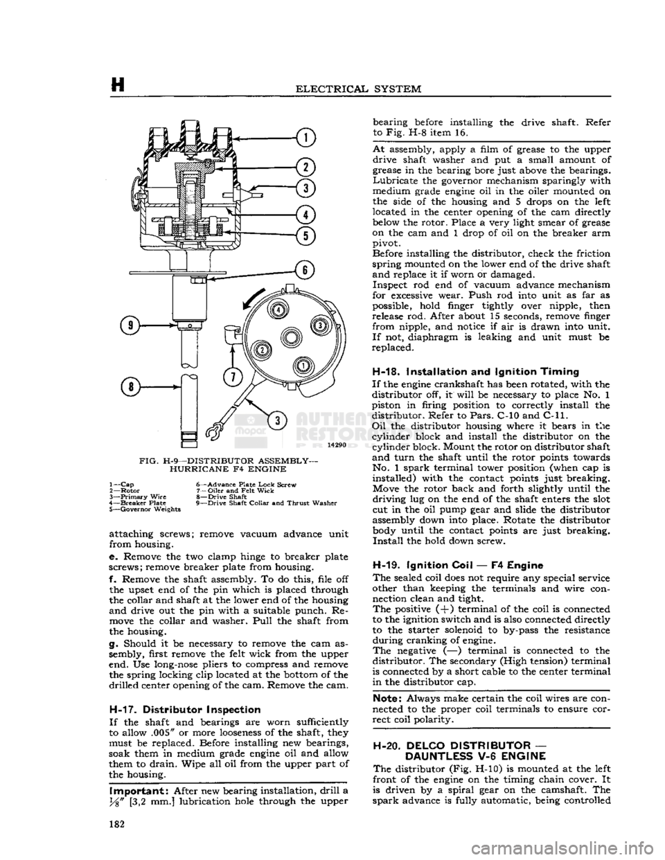
FIG.
H-9—DISTRIBUTOR ASSEMBLY- HURRICANE F4 ENGINE 1—
Cap
6—Advance Plate
Lock
Screw
2—
Rotor
7—Oiler and
Felt
Wick
3—
Primary
Wire
8—Drive Shaft
4—
Breaker
Plate 9—Drive Shaft
Collar
and
Thrust
Washer 5—
Governor
Weights
attaching screws; remove vacuum advance unit
from housing.
e. Remove the two clamp
hinge
to breaker plate
screws; remove breaker plate from housing.
f. Remove the shaft assembly. To do this, file off
the upset end of the pin which is placed through
the collar and shaft at the lower end of the housing
and
drive out the pin with a suitable punch. Re
move
the collar and washer.
Pull
the shaft from
the housing.
g. Should it be necessary to remove the cam as
sembly, first remove the
felt
wick from the upper
end. Use
long-nose
pliers to compress and remove the spring locking clip located at the
bottom
of the
drilled
center opening of the cam. Remove the cam.
H-17.
Distributor Inspection
If
the shaft and bearings are worn sufficiently
to allow .005" or more
looseness
of the shaft,
they
must be replaced. Before installing new bearings,
soak them in medium grade
engine
oil and allow
them to
drain.
Wipe all oil from the upper part of
the housing.
Important:
After new bearing installation,
drill
a
y%"
[3,2 mm.] lubrication
hole
through the upper bearing
before
installing the drive shaft. Refer
to Fig. H-8 item 16.
At
assembly, apply a film of grease to the upper
drive
shaft washer and put a small amount of
grease in the bearing bore just
above
the bearings.
Lubricate
the governor mechanism sparingly with
medium grade
engine
oil in the oiler mounted on
the side of the housing and 5 drops on the
left
located in the center opening of the cam directly
below
the rotor. Place a very light smear of grease
on the cam and 1 drop of oil on the breaker arm pivot.
Before installing the distributor, check the friction
spring
mounted on the lower end of the drive shaft
and
replace it if worn or damaged. Inspect rod end of vacuum advance mechanism
for
excessive
wear. Push rod
into
unit as far as
possible, hold finger tightly over nipple, then release rod. After about 15 seconds, remove finger
from nipple, and
notice
if air is drawn
into
unit.
If
not, diaphragm is leaking and unit must be
replaced.
H-18.
Installation and Ignition
Timing
If
the
engine
crankshaft has
been
rotated, with the
distributor off, it
will
be necessary to place No. 1
piston in firing position to correctly install the distributor. Refer to
Pars.
C-10 and
C-ll. Oil
the distributor housing where it bears in the
cylinder
block and install the distributor on the
cylinder
block. Mount the rotor on distributor shaft
and
turn
the shaft until the rotor
points
towards No. 1
spark
terminal tower position (when cap is installed) with the contact
points
just breaking. Move the rotor back and forth slightly until the
driving
lug on the end of the shaft enters the
slot
cut in the oil pump gear and slide the distributor
assembly down
into
place. Rotate the distributor
body
until the contact
points
are just breaking.
Install
the hold down screw.
H-19.
Ignition
Coil
— F4 Engine
The
sealed coil
does
not require any special service
other than keeping the terminals and wire con nection clean and tight.
The
positive (+) terminal of the coil is connected
to the ignition switch and is also connected directly
to the starter solenoid to by-pass the resistance
during
cranking of
engine.
The
negative
(—) terminal is connected to the
distributor. The secondary (High tension) terminal
is connected by a short cable to the center terminal
in
the distributor cap.
Note:
Always make certain the coil wires are con
nected to the proper coil terminals to ensure cor
rect coil polarity.
H-20. DELCO DISTRIBUTOR
—
DAUNTLESS
V-6
ENGINE
The
distributor (Fig. H-10) is mounted at the
left
front of the
engine
on the timing chain cover. It
is driven by a
spiral
gear on the camshaft. The
spark
advance is fully automatic, being controlled 182
Page 183 of 376
'Jeep*
UNIVERSAL
SERIES SERVICE
MANUAL
H
|
13399
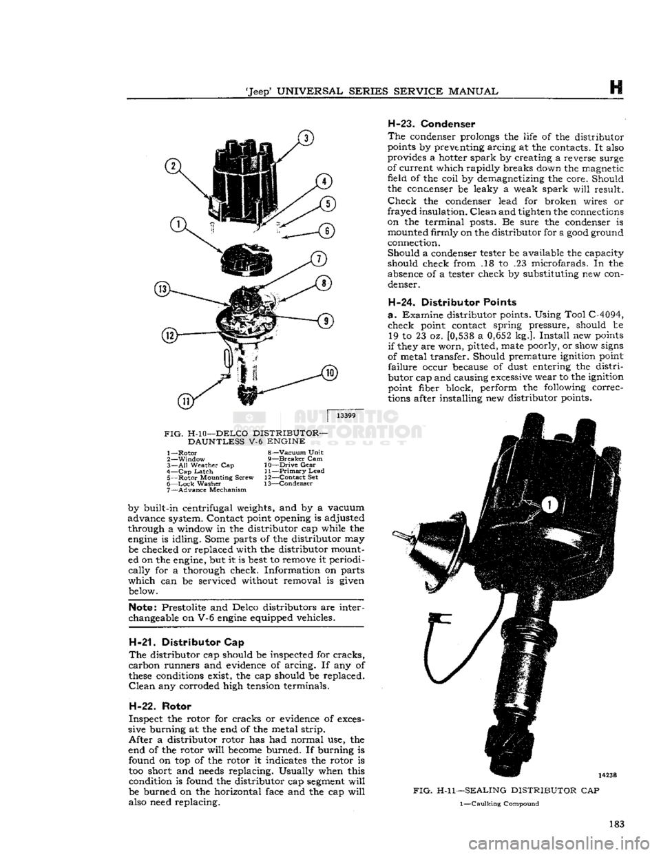
FIG.
H-10—DELCO
DISTRIBUTOR—
DAUNTLESS
V-6
ENGINE
1—
Rotor
8—Vacuum
Unit
2—
Window
9—Breaker Cam
3—
All
Weather Cap
10—Drive
Gear
4—
Cap
Latch
11—Primary Lead 5—
Rotor
Mounting
Screw 12—Contact Set
6—
Lock
Washer 13—Condenser
7—
Advance
Mechanism
by
built-in
centrifugal weights, and by a vacuum
advance
system. Contact point opening is adjusted
through
a window in the distributor cap
while
the engine is
idling.
Some
parts
of the distributor may be checked or replaced
with
the distributor mount
ed on the engine, but it is
best
to remove it periodi
cally
for a thorough check. Information on
parts
which
can be serviced without removal is given
below.
Note:
Prestolite and Delco distributors are inter
changeable
on V-6 engine equipped vehicles.
H-21.
Distributor Cap
The distributor cap should be inspected for cracks,
carbon runners and evidence of arcing. If any of
these
conditions exist, the cap should be replaced. Clean any corroded high tension terminals.
H-22.
Rotor
Inspect the rotor for cracks or evidence of
exces
sive burning at the end of the metal strip.
After
a distributor rotor has had normal use, the
end of the rotor
will
become
burned. If burning is
found
on top of the rotor it indicates the rotor is too short and
needs
replacing. Usually when this
condition
is found the distributor cap
segment
will
be burned on the horizontal face and the cap
will
also
need
replacing.
H-23.
Condenser
The
condenser
prolongs the
life
of the distributor
points by preventing arcing at the contacts. It
also
provides a hotter spark by creating a
reverse
surge
of
current
which
rapidly
breaks
down the magnetic
field
of the
coil
by demagnetizing the core. Should
the
ccnaenser
be leaky a weak spark
will
result. Check the
condenser
lead for broken wires or
frayed
insulation.
Clean and tighten the connections
on
the terminal
posts.
Be
sure
the
condenser
is mounted
firmly
on the distributor for a good ground
connection.
Should
a
condenser
tester
be available the capacity
should check
from
.18 to .23 microfarads. In the
absence
of a
tester
check by substituting new con
denser.
H-24. Distributor Points
a-
Examine distributor points. Using
Tool
C-4094, check point contact spring
pressure,
should be 19 to 23 oz. [0,538 a 0,652 kg.]. Install new points
if
they are
worn,
pitted,
mate
poorly, or show
signs
of
metal transfer. Should premature
ignition
point
failure
occur
because
of dust entering the
distri
butor cap and causing
excessive
wear to the
ignition
point
fiber block, perform the
following
correc
tions after installing new distributor points.
FIG. H-l
1—SEALING
DISTRIBUTOR
CAP
1—Caulking
Compound
183
Page 184 of 376
H
ELECTRICAL
SYSTEM
14237
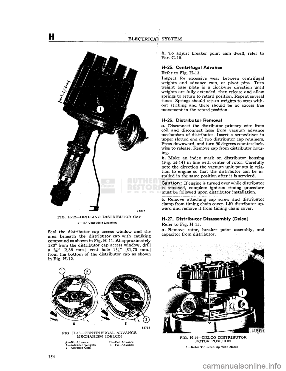
FIG.
H-l2—DRILLING DISTRIBUTOR
CAP 1—%'
Vent
Hole
Location
Seal
the distributor cap access window and the
area
beneath the distributor cap with caulking
compound as shown in
Fig. H-ll.
At approximately
180°
from the distributor cap access window,
drill
a
[2,38 mm.] vent
hole
[31,75
mm.]
from the
bottom
of the distributor cap as shown
in
Fig. H-l2. b. To adjust breaker point cam dwell, refer to
Par.
C-10.
H-25.
Centrifugal Advance
Refer
to Fig. H-13.
Inspect for
excessive
wear
between
centrifugal
weights
and advance cam, or pivot pins.
Turn
weight
base plate in a clockwise direction until
weights
are fully extended, then release and allow springs to return to retard position. Repeat several times. Springs should return
weights
to
stop
without sticking and there should be no
excess
free
movement
in the retard position.
H-26.
Distributor Removal
a.
Disconnect the distributor primary wire from
coil
and disconnect
hose
from vacuum advance
mechanism of distributor. Insert a screwdriver in upper
slotted
end of two distributor cap retainers.
Press
downward, and turn 90
degrees
counterclock
wise to release. Remove cap from distributor hous ing.
b. Make an index
mark
on distributor housing
(Fig.
H-14) in line with center of rotor. Carefully
note
the direction the vacuum unit
points
in
rela
tion to
engine
so that the distributor can be in
stalled in the same position after it is serviced.
Caution:
If
engine
is turned over while distributor is removed,
complete
ignition timing procedure
must be followed upon distributor installation.
c. Remove attaching cap screw and distributor
clamp from timing chain cover.
Lift
distributor up
ward
and remove it from timing chain cover.
H-27.
Distributor Disassembly (Delco)
Refer
to Fig. H-l5.
a.
Remove rotor, breaker point assembly, and capacitor from distributor.
FIG.
H-13—CENTRIFUGAL ADVANCE
MECHANISM (DELCO)
A—No
Advance
1—
Advance
Weights
2—
Advance
Cam
B—Full
Advance
3—Full
Advance
FIG.
H-14—DELCO DISTRIBUTOR
ROTOR
POSITION
1
—Rotor
Tip
Lined
Up
With
Notch
184
Page 187 of 376
'Jeep'
UNIVERSAL
SERIES SERVICE
MANUAL
H
12746
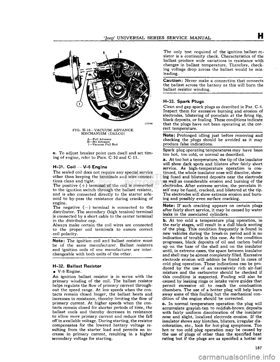
FIG.
H-l8—VACUUM
ADVANCE
MECHANISM
(DELCO)
A—Full
Advance
B—No
Advance
1—Vacuum
Pull
Rod
e.
To adjust breaker point cam dwell and set tim
ing of engine, refer to
Pars.
C-10 and
C-ll.
H-31. Coil
— V-6 Engine
The
sealed coil
does
not require any special service
other than keeping the terminals and wire connec
tions clean and tight.
The
positive (+) terminal of the coil is connected
to the ignition switch through the ballast resistor,
and
is also connected directly to the starter
sole
noid to by-pass the resistance during cranking of
engine.
The
negative (—) terminal is connected to the
distributor.
The secondary (high tension) terminal
is connected by a short cable to the center terminal
in
the distributor cap.
Always
make certain the coil wires are connected to the proper coil terminals to ensure correct
coil
polarity.
Note:
The ignition coil and ballast resistor must
be of the same manufacturer. Ballast resistors
and
ignition coils of one manufacturer are interchangeable with both units of the other. H-32.
Ballast
Resistor
•
V-6 Engine.
An
ignition ballast resistor is in series with the
primary
winding of the coil. The ballast resistor
helps regulate the flow of
primary
current through
out the speed range. At low
speeds
when the con
tacts remain closed longer, the ballast heats and
increases in resistance, thereby limiting the flow of
primary
current. At higher
speeds
when the con
tacts remain closed for shorter periods of time, the ballast
cools
and thereby decreases in resistance
to allow more
primary
current and reduce the
fall
off
in
available voltage.
During
starting, the resistor compensates for the lowered battery
voltage
re
sulting from the starter load and permits an in crease in
primary
current, resulting in a higher
secondary
voltage
for starting.
The
only
test
required of the ignition ballast re
sistor is a continuity check. Characteristics of the ballast produce wide variations in resistance with
changes in ballast temperature. Therefore, check ing
voltage
drop across the ballast would be mis
leading.
Caution:
Never make a connection that connects
the ballast across the battery as this
will
burn
the ballast resistor winding.
H-33.
Spark
Plugs
Clean
and gap
spark
plugs as described in
Par.
C-4.
Inspect them for excessive burning and erosion of
electrodes, blistering of porcelain at the firing tip,
black
deposits, or fouling. These conditions indicate
that the plugs have not been operating at the cor
rect
temperature.
Note:
Prolonged idling just before removing and
checking the plugs should be avoided as it may
produce false indications.
Spark
plug operating temperatures may have been
too hot, too cold, or normal as described.
a.
At too hot a temperature, the tip of the insulator
will
show
dark
spots
and blisters after fairly short service. As high-temperature operation is con
tinued, the whole insulator
nose
will
discolor, show
ing fused and blistered
deposits
near the electrode
as well as considerable erosion and burning of the
electrodes. After extreme service, the porcelain it self may be fused, cracked, and blistered at the tip.
The
electrodes
will
show extreme erosion and
burn
ing and possibly even surface cracking.
Note:
If such cracking appears on certain plugs
after fairly short service, it may be caused by water
leaks in the associated cylinders.
b. At too cold a temperature plug operation, in
the early
stages,
will
result in a
dull
black
sooting
of the plug.
This
condition frequently is found in new vehicles during the break-in period and is no
indication of trouble in this case. As the condition progresses, black
deposits
of oil and carbon build
up on the base of the shell and on the insulator
until,
in extreme cases, the space
between
insulator
and
shell may be almost completely filled. Excessive
electrode erosion
will
seldom be found in cases of cold plug operation. These indications can be pro
duced by the use of an excessively
rich
air-fuel mixture and the carburetor should be checked if
this condition is suspected. Fouling
will
also be
caused by leaking rings or intake valve
guides
that
permit excessive oil to reach the combustion
chambers.
The use of a hotter plug
will
help
burn
away
some
of this fouling but the mechanical con dition of the
engine
should be corrected.
c. In normal temperature operation the plug
will
accumulate grayish-tan to reddish-brown
deposits
with
fairly uniform discoloration of the insulator
nose
and slight, localized electrode erosion. If the
insulator shows any blotches, blisters,
irregular
dis
coloration, etc., look for hot-plug symptoms. Too
hot or too cold plug operation may be caused by
the use of plugs of other than the specified heat
rating
but if the plugs are as specified a hotter or 187
Page 192 of 376
H
ELECTRICAL
SYSTEM
Regulator
ground screw to battery ground post
—.03-volt maximum.
Generator
frame to battery ground post—.03-volt
maximum.
H-47.
Test Procedure
a.
Circuit
Breaker—Connect
an ammeter in series between the regulator B-terminal and the lead
wire
removed from that terminal. Connect a
voltmeter between the regulator
A-terminal
and the regulator mounting base. Disconnect the field lead
from
the regulator
F-terminal
and insert a variable resistance (3 amp., 50 ohm capacity) between the
lead
and the regulator terminal. Run the generator
at about 1000 generator rpm. Insert all the re
sistance in the field
circuit,
then slowly reduce the
resistance noting the voltage reading just before the change caused by the closing of the circuit
breaker.
Increase the charging rate to the figure
specified for the regulator being tested then reduce
the charging rate by inserting resistance in the
field
circuit.
Note
the voltmeter and ammeter
reading
just before the circuit breaker
opens
and
the ammeter reading drops to zero. The closing voltage and the opening voltage or current should
be within the limits specified. An accurate method
for noting the exact instant of the opening or closing
of the circuit breaker is to connect a headphone (2000 ohms or higher) to the battery and armature
terminals
of the regulator. When the contacts
open or close a
click
will
be
heard
in the headphones.
To
adjust the closing voltage change the armature
spring
tension by bending the hanger at the lower end of the spring. Increase the spring tension to
raise
the closing voltage or decrease the tension
to lower the closing voltage. To adjust the opening voltage raise or lower the stationary contact
keeping the contacts perfectly aligned. Increasing
the contact gap lowers the opening
'
voltage.
Change
the contact gap by expanding or contract
ing the stationary contact bracket, keeping the
contacts aligned. Do not adjust the gap between
the contacts to less than the specified minimum.
b.
Voltage Regulator—Connect the ammeter as in
step
a. Connect the voltmeter between the regulator
B-terminal
and the regulator base. Remove the
variable
resistance from the field
circuit.
Run the
generator at
half
output for 15 minutes to bring
the regulator to normal operating temperature.
Keep
the cover on the regulator during the
warm-
up period and also when taking readings.
Stop the engine then bring it up to approximately 2500 generator rpm. Adjust the amperage to
half
maximum
output by turning on lights or accessor
ies and then
note
the voltmeter reading.
This
read
ing should be within the limits specified for the voltage regulator operation. To adjust the oper
ating voltage change the
armature
spring tension by
bending the hanger at the lower end of the
arma
ture
spring. After each adjustment
stop
the engine then restart it.
Bring
it up to speed and adjust the
current
before taking a reading. In order to obtain
an
accurate indication of the operation of the volt
age regulator unit connect a headphone (2000 ohm
or
higher) between the
F-terminal
and ground to
pick
up the sound of the opening and closing of the
contacts. The clicks should be regular and clear without irregularities or missing. If the
tone
is not
clear
and regular remove the regulator cover and
inspect the contacts. The contacts should be flat
and
not burned excessively and should be aligned
to make
full
face contact. If the contacts need
cleaning refer to paragraph d for the method.
c.
Current
Regulator—Connect the regulator and the
test
equipment as in
step
b. Running the generator at approximately 3000 generator rpm.,
turn
on lights and accessories so that the generator must charge at maximum rate. The ammeter should give a reading within the limits specified.
To
adjust opening amperage, change the armature
spring
tension by bending the hanger at the lower
end of the armature spring. After each adjustment,
stop
the engine, then restart it.
Bring
the engine up to speed and take an ammeter reading. Keep
the cover on the regulator when taking
these
readings.
Connect
a headphone (2000 ohms or higher) be
tween the regulator
F-terminal
and ground to pick
up the sound of opening and closing of the contacts.
Clear,
regular clicks should be heard over the
headphones; they should not be
irregular
or missing.
If
the
tone
is not clear and regular remove the
regulator cover and inspect the contacts. The
contacts should be flat and not burned excessively
and
should be aligned to make
full
face contact. If
the contacts need cleaning refer to paragraph d.
below for the method.
d.
Contacts—Inspect the contacts on all three
units.
In normal use the contacts
will
become
grayed.
If the contacts are burned or dirty or if they are not smooth, file the contacts with a #6
American,
Swiss cut, equalling file. Move the file
parallel
and lengthwise to the armature.
File
just
enough so that the contacts present a smooth
sur
face toward each other. It is not necessary to remove every trace of pitting. After filing, dampen
a
piece of linen or lintless bond tape in refined
carbon
tetrachloride and draw the tape between
the contacts. Repeat with a dry piece of tape. Use
clean
tape for each set of contacts.
e. Recheck—Operate the unit at
half
maximum
output for five minutes with the cover on the regu
lator.
Repeat the testing procedure for all units as described in a, b, c above. Be sure cover is on regu
lator
when taking readings.
H-48.
Quick
Checks
H-49.
Low Charging Rate with a
Fully
Charged
Battery
A
fully charged battery and a low charging rate
indicates normal regulator operation.
A
further check of the regulator operation can be
made by using the starting motor for 5 to 10
seconds with the ignition switch in the "off" posi tion.
Then
start the engine and operate at a genera
tor speed of 2500 to 3000 rpm. The charging rate should rise to its maximum value then taper off to
a
minimum charge as the battery becomes charged.
H-50.
High Charging Rate with a
Fully
Charged
Battery
This
is usually an indication that the voltage regu
lator
is not operating correctly. The high voltage 192