maintenance JEEP CJ 1953 Owner's Guide
[x] Cancel search | Manufacturer: JEEP, Model Year: 1953, Model line: CJ, Model: JEEP CJ 1953Pages: 376, PDF Size: 19.96 MB
Page 323 of 376
'Jeep'
UNIVERSAL
SERIES SERVICE
MANUAL
P
BRAKES
SUBJECT
PAR
GENERAL.
. P-l
Brake
Maintenance P-5
Master
Cylinder.
P-2
Parking
Brake
P-3
Transmission
Brake
P-4
BRAKE SERVICE
.P-6 Bleeding Brakes P-7
Brake
Adjustments P-14
Brake
Hoses P-8
Brake
Shoe
Initial
Adjustment P-l9
Brake
Shoe Installation P-l8
Brake
Pedal Adjustment P-9
Hand
Brake.
P-10 Inspection P-17
SUBJECT
PAR
Brake
Shoe Removal P-l6
Master
Cylinder Reconditioned. . P-20
Parking
Brake
Adjustment
.P-l 1
Relining
Transmission
Brake
P-13
Relining
Wheel
Brake
P-l5
Transmission
Brake
Adjustment .P-12
Wheel
Brake
Units P-14
Wheel
Cylinder Reconditioning P-21
TROUBLESHOOTING
P-2 2 Squeaky Brakes P-23
Rattles in Brakes P-24
SERVICE
DIAGNOSIS.
P-25
SPECIFICATIONS
P-2 6
P-1. GENERAL
A
double-safety
hydraulic brake system in con
junction with self-adjusting wheel brake units are
standard
equipment on all current production
'Jeep* vehicles. The
double-safety
brake system
Is
equipped with dual
stop
light switches that op
erate independently of each other, thus eliminating
possible
stop
light failure. Service information for
self adjusting brakes starts with Par. P-14.
All
four-wheel-drive vehicles are equipped with a transmission brake that operates in the drive line
and
is mounted to the rear of the transfer case. Two-wheel-drive vehicles
(DJ-5,
DJ-6)
are equipped
with a hand-operated parking brake that operates at the rear wheels.
P-2.
Master Cylinder —
Double Safety-Brake System
The
master cylinder (cast integrally with the res
ervoir)
is the compensating type. Refer to Fig.
P-2 and P-13.
Action by the brake pedal
moves
the master cylinder piston which exerts pressure on the fluid in
the cylinder and lines. 12914
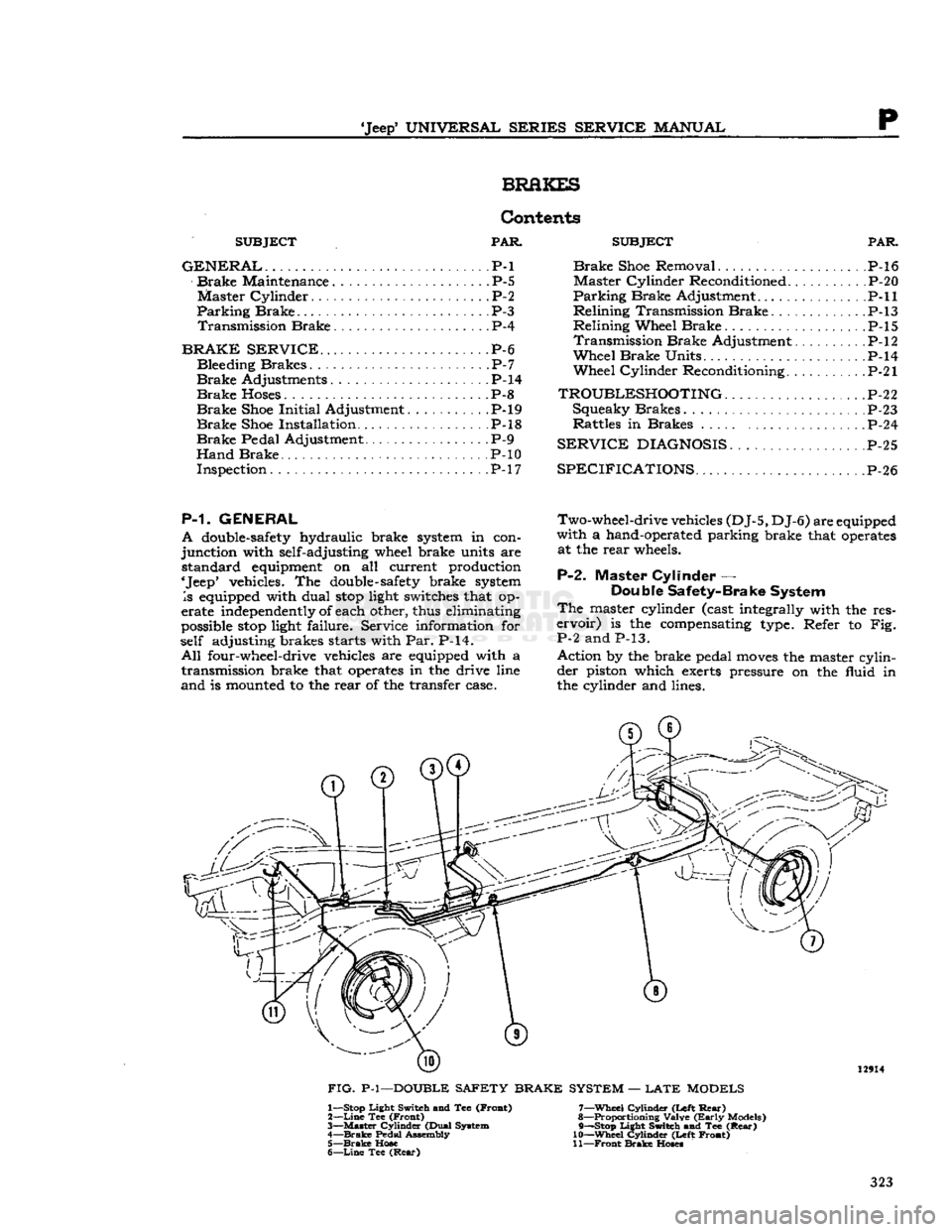
FIG.
P-l—DOUBLE SAFETY BRAKE SYSTEM —
LATE
MODELS 1— Stop Light Switch and Tee (Froat)
2—
Line
Tee (Front)
3—
Master
Cylinder (Dual System
4—
Brake
Pedal Assembly 5—
Brake
Hose
6—
Line
Tee
(Rear)
7—
Wheel
Cylinder (Left
Rear)
8— Proportioning Valve
(Early
Models)
9— —Stop Light Switch and Tee
(Rear)
10—
Wheel
Cylinder (Left Front)
11—
Front
Brake
Hoses
323
Page 325 of 376
'Jeep'
UNIVERSAL
SERIES SERVICE
MANUAL
P The
standard parking brakes (Fig. P-3) consist of
cable-controlled linkage for applying the rear wheel
brake
shoes
mechanically. A single cable from the
parking
brake control lever is connected, by means of an equalizer, to cables leading to individual rear
brakes.
A lever attached to the secondary
shoe,
with a link acting against the
primary
shoe,
expands the
shoes
into
contact with the drums.
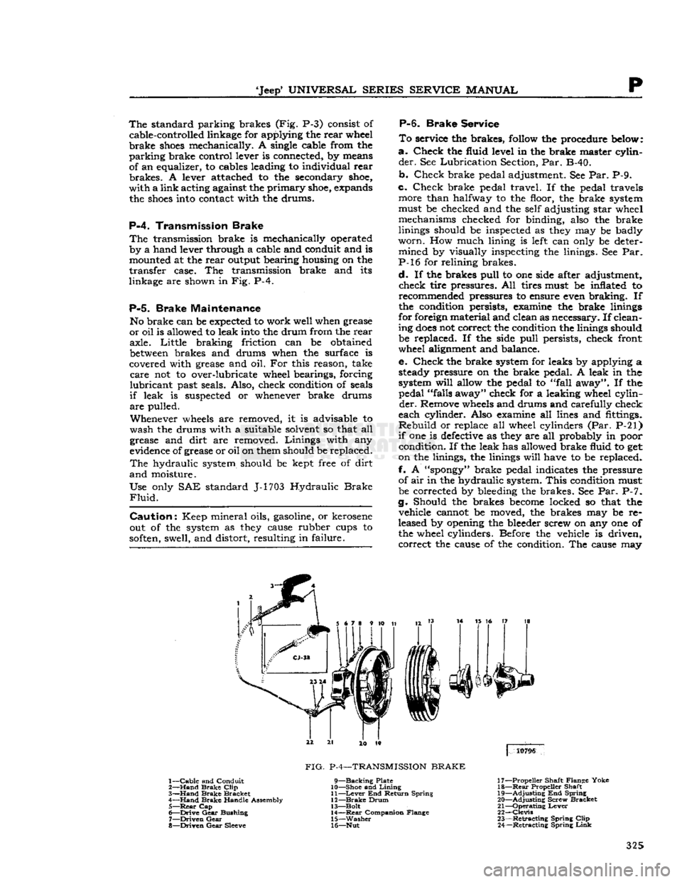
P-4.
Transmission Brake
The
transmission brake is mechanically operated
by a hand lever through a cable and conduit and is mounted at the rear output bearing housing on the
transfer case. The transmission brake and its
linkage are shown in Fig. P-4.
P-5.
Brake Maintenance
No brake can be
expected
to work well when grease
or oil is allowed to leak
into
the drum from the rear axle. Little braking friction can be obtained
between
brakes and drums when the surface is
covered with grease and oil. For this reason, take
care
not to over-lubricate wheel bearings, forcing
lubricant
past seals. Also, check condition of seals
if
leak is suspected or whenever brake drums
are
pulled.
Whenever
wheels
are removed, it is advisable to
wash the drums with a suitable solvent so that all
grease and dirt are removed. Linings with any
evidence of grease or oil on them should be replaced.
The
hydraulic system should be kept free of dirt
and
moisture.
Use only SAE standard J-1703 Hydraulic
Brake
Fluid.
Caution:
Keep mineral oils, gasoline, or kerosene
out of the system as
they
cause rubber cups to
soften,
swell, and distort, resulting in failure.
P-6.
Brake
Service
To
service the brakes,
follow
the procedure
below:
a.
Check the fluid level in the brake master cylin
der.
See Lubrication Section, Par. B-40.
b. Check brake pedal adjustment. See Par. P-9.
c. Check brake pedal travel. If the pedal travels more than halfway to the floor, the brake system
must be checked and the self adjusting star wheel mechanisms checked for binding, also the brake
linings should be inspected as
they
may be badly
worn.
How much lining is
left
can only be deter mined by visually inspecting the linings. See Par.
P-l6 for relining brakes.
d.
If the brakes pull to one side after adjustment, check tire pressures. All tires must be inflated to recommended pressures to ensure even braking. If
the condition persists, examine the brake linings
for foreign material and clean as necessary. If clean
ing
does
not correct the condition the linings should be replaced. If the side pull persists, check front
wheel alignment and balance.
e. Check the brake system for leaks by applying a steady pressure on the brake pedal. A leak in the
system
will
allow the pedal to "fall away". If the pedal "falls away" check for a leaking wheel cylin
der.
Remove
wheels
and drums and carefully check
each cylinder. Also examine all lines and fittings.
Rebuild
or replace all wheel cylinders (Par. P-21)
if
one is
defective
as
they
are all probably in poor condition. If the leak has allowed brake fluid to get
on the linings, the linings
will
have to be replaced.
f. A
"spongy"
brake pedal indicates the pressure of air in the hydraulic system.
This
condition must
be corrected by bleeding the brakes. See Par. P-7.
g. Should the brakes
become
locked so that the vehicle cannot be moved, the brakes may be re
leased by opening the bleeder screw on any one of the wheel cylinders. Before the vehicle is driven, correct the cause of the condition. The cause may
3
14 15 16 17 18
4
10796
1—
Cable
and Conduit
2—
Hand
Brake
Clip
3—
Hand
Brake
Bracket
4—
Hand
Brake
Handle Assembly 5—
Rear
Cap
6—
Drive
Gear
Bushing
7—
Driven
Gear
8—
Driven
Gear
Sleeve
FIG.
P-4—TRANSMISSION
BRAKE
9—Backing
Plate
10— Shoe and
Lining
11—
Lever
End Return Spring
12—
Brake
Drum
13— Bolt 14—
Rear
Companion Flange
15—
Washer
16— Nut 17— Propeller Shaft Flange Yoke
18—
Rear
Propeller Shaft
19—
Adjusting
End Spring
20—
Adjusting
Screw Bracket
21—
Operating
Lever
22—
Clevis
23—
Retracting
Spring
Clip
24—
Retracting
Spring
Link
325
Page 339 of 376
'Jeep'
UNIVERSAL
SERIES
SERVICE
MANUAL
Q
ice, provide maximum safety over all
types
of
terrain,
and furnish the medium on which the
vehicle can be maneuvered with ease. Although
there are other
elements
of tire service, inflation maintenance is the most important and in many
instances the most neglected. The tire pressure should be maintained for safe operation. An under- inflated tire is dangerous as too much flexing can
cause breakage of the casing. Overinflation in time
may
cause a blowout.
Upon
careful inspection of tires, it may be found
that improper wheel alignment, balance, grabbing
brakes,
poor driving habits, fast cornering or other
conditions are the cause of wear. Such conditions
should be corrected.
a.
UNDERINFLATION
Underinflation
distorts the normal contour of the
tire
body and the tire
bulges
or "bellies out" with
an
extreme flexing action.
This
wears the tread at the
edges
more than the center and generates
excessive internal heat, weakening the cords and
resulting
in bruises, broken cords or ply separation.
Underinflation
also leads to rim bruises as in sufficient resistance is provided to prevent the tire
from
being jammed against the rim and crushed
or
cut when the tire strikes a
curb,
rock, or rut.
b.
OVERINFLATION
When
a tire is
overinf
lated,
increased tension caused by excessive pressure prevents proper deflection of
the sidewalls.
This
results in wear in the center of the tread and the tire also
loses
its ability to absorb
road
shocks. Under this increased
strain,
cords in the tread area eventually snap under impact, causing a casing break.
c.
MISALIGNMENT
WEAR
Excessive
wheel camber causes the tires to run at an angle to the road when camber is incorrect
it
will
cause excessive wear on one side of the
tire
tread.
Front
wheels should be straight ahead or toe-in slightly. When there is excessive toe-in or
toe-out,
tires
will
revolve with a side motion and scrape
the tread rubber off.
Front
tires
will
show wear on the outside with too great a toe-in condition
and
on the inside with a
toe-out
condition.
d.
BALANCE
Cupping
and bald spotting of tires is associated
with
wear on a vehicle driven mostly at high-way
speeds
without the recommended tire rotation and
with
unbalance conditions.
Q-12.
Tire
Care
Note;
For satisfactory 4-wheel drive operation, a
4-wheel drive vehicle
MUST
be equipped with the same size tires of equal circumference on all
four wheels. The tires must then be inflated to
proper
factory recommended pressures at all times.
Tire
pressure, tire rotation, wheel balance, and wheel alignment are the four vital factors that in
fluence the
extent
of tire life and the
ease
and safety of vehicle control.
Four
of the most common
tire
troubles are:
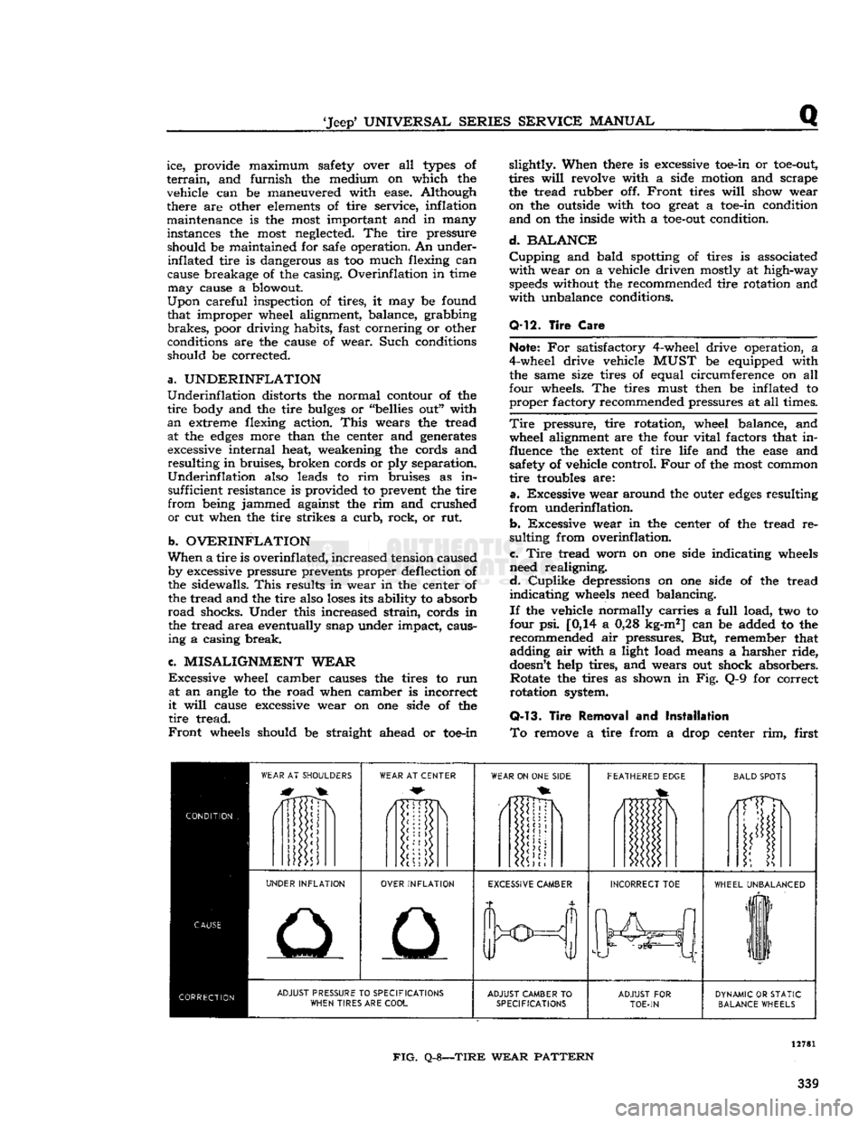
a.
Excessive wear around the outer
edges
resulting
from
underinflation.
b.
Excessive wear in the center of the tread re
sulting from overinflation.
c.
Tire
tread worn on one side indicating wheels
need realigning.
d.
Cuplike
depressions on one side of the tread
indicating
wheels need balancing.
If
the vehicle normally carries a
full
load, two to
four psi. [0,14 a 0,28 kg-m2] can be added to the
recommended air pressures. But, remember that adding air with a light load means a harsher ride,
doesn't
help tires, and wears out shock absorbers. Rotate the tires as shown in Fig. Q-9 for correct
rotation system.
Q-13.
Tire
Removal
and
Installation
To
remove a tire from a drop center rim, first
WEAR
AT SHOULDERS
WEAR
AT CENTER
WEAR
ON ONE
SIDE
FEATHERED
EDGE
BALD
SPOTS
/1TTDN
i
UNDER
INFLATION
OVER
INFLATION
EXCESSIVE
CAMBER
INCORRECT
TOE
WHEEL
UNBALANCED
liF
11
ADJUST
PRESSURE TO
SPECIFICATIONS
WHEN
TIRES ARE
COOL
ADJUST
CAMBER
TO
SPECIFICATIONS
ADJUST
FOR
TOE-IN
DYNAMIC
OR
STATIC
BALANCE
WHEELS
FIG.
Q-8—TIRE
WEAR
PATTERN
339
Page 357 of 376
'Jeep'
UNIVERSAL SERIES SERVICE
MANUAL
u
MISCEIiLaNEOUS
Contents
SUBJECT
PAR.
Abbreviations
U-15
Extra
Equipment U-2
Front
Bumper Weight U-9
Governor
U-3
Governor
Adjustment U-4
Governor
Maintenance. U-6
U-1. GENERAL
Miscellaneous information included in this sectioi
includes coverage of extra equipment, special
tools,
torque specifications, and charts and tables.
U-2. EXTRA
EQUIPMENT
Much
of the utility of the
*
Jeep*
Universal
is due to
the extra equipment which has been designed to adapt it for farming and industry. The mainte
nance and use of
some
of this equipment is out
lined
in this section.
U-3.
Governor Assembly
The
Novi governor is supplied for models equipped
with
the F4 engine.
This
is a centrifugal type governor and is illustrated in Fig. U-2. Complete
installation
instructions are supplied with each
assembly. Adjustment and operating procedures
are
given below.
U-4.
Governor Adjustment
a.
Adjust the carburetor to obtain smooth
engine
idle at 600 rpm., then
stop
the engine.
b.
Check
throttle linkage to ensure maximum
throttle opening. Be certain that throttle and
governor linkage is free.
c.
Place the carburetor throttle in wide-open posi tion and
pull
the governor control handle out to
the last notch. Adjust the governor to bellcrank
rod
so that the linkage
will
hold the carburetor
throttle in wide-open position.
d.
Close the governor control and start the
engine
Again
pull
the control out to the last notch and
adjust
the length of the cable at adjusting yoke so
that the
engine
will
run at
2600
rpm. Close the
control
to recheck the linkage for free action and
to make sure the
engine
will
return to 600 rpm.
idle speed.
If
the
engine
runs faster than this speed,
loosen
the lock nut which locks the governor hand control
handle on the dash to the rod and back off the
handle until the carburetor idle speed adjusting
screw
bears on the stop. Tighten the lock nut.
In
the absence of electrical tachometer equipment,
engine
speed may be determined by the speedom
eter. Safely
jack
up the
rear
wheels and be sure the front wheel drive is not
engaged.
When driving
the
rear
wheels in high or direct transmission gear,
the
speedometer
will
read from 13j^ to 15 mph. [21.6 to 24.0 kph.] at an
engine
speed of from 900
to 1000 rpm.
SUBJECT
PAR.
Heater
U-10 Miscellaneous Data U-16
Pintle
Hook 1X7
Special
Tools. U-ll
Torque
Specifications U-13, 14, 15
Standard
and Recommended Tools
j.
.U-12
U-5.
Novi Governor Operation /
The
Novi governor is directly belted to the F4
engine
as no clutch is provided to disconnect the
drive.
To
operate the vehicle
WITHOUT
governor con
trol,
push the governor hand control all the way
IN
against the instrument panel.
To
operate the vehicle
WITH
governor control,
pull
the governor hand control handle out. The
hand
control has nine notched positions. Pulling the
control
out to the first notch
sets
the controlled
engine
speed at approximately 1000 rpm. and each successive notch increases the speed 200 rpm.
until
2600
rpm. is reached in the ninth notch. The
hand
control may be released by turning the han dle one-quarter
turn
in either direction.
When
the
engine
is being operated under governor
control
(hand control out) the controlled
engine
speed may be
exceeded
at any time by depressing
the
foot
accelerator in the conventional manner to
secure a greater carburetor throttle opening than
that determined by the governor hand control
setting.
U-6.
Governor Maintenance
The
belt tension may be adjusted by raising or
lowering the governor in the slotted
holes
in the mounting bracket. Keep the pulleys and belt free
of
dirt
and oil. Belt slippage
will
affect governor
operation and a tight belt may cause
rapid
wear
of the governor shaft and bearings. Adjust it to
allow Yi' [12,7 mm.] depression midway
between
the pulleys with thumb pressure.
There
is little wear of the internal parts for they
operate in oil. The governor housings are equipped
with
both
fill
and
drain
plugs and also with level
indicating
plugs.
Check
the oil level at each vehicle
lubrication
and change the oil each time the en
gine
oil is changed using the same grade oil used
in
the engine.
Caution:
Do not
fill
the governor housing above
the level plug. Overfilling
will
prevent governor
control
and possibly cause damage to governor in
ternal
parts. The capacity of
these
governors is two fluid ounces [59,15 cm3]. The filler plug is
also a vent which should be cleaned thoroughly at
each oil change to be sure that the vent operates.
U-7.
Pintle Hook
The
standard type pintle hook, Fig. U-1, affords a
safe, easy hitch for towing a
trailer
or other vehicle. 357
Page 371 of 376
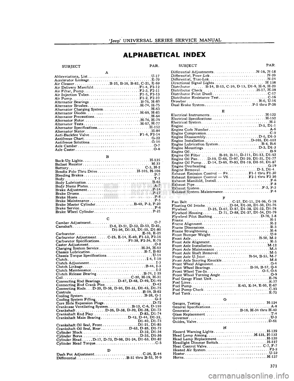
'Jeep'
UNIVERSAL
SERIES SERVICE
MANUAL
ALPHABETICAL INDEX
SUBJECT PAR.
SUBJECT
PAR.
Abbreviations,
List
U-17 Accelerator Linkage E-70
Air
Cleaner B-25, B-26, B-82, C-21, E-69
Air
Delivery Manifold Fl-4, F2-12
Air
Filter, Pump • F2-3, F2-11
Air
Injection Tubes Fl-5, F2-13
Air
Pump Fl-2, F2-10
Alternator Bearings B-76, H-80
Alternator Brushes H-74, H-75
Alternator Charging System •
•
H-63
Alternator
Diodes
H-69, H-85
Alternator Precautions H-64 Alternator Rotor H-76, H-79
Alternator Tests H-67, H-77 Alternator Specifications H-l 52
Alternator Stator H-84
Anti-Backfire
Valve Fl-6, F2-14
Antifreeze
Chart
• G-22 Antifreeze
Solutions
- G-16
Axle Camber O-l
Axle Caster 0-8
Back-Up
Lights H-135
Ballast
Resistor. H-32 Battery C-3, H-2 Bendix Folo-Thru Drive H-105, H-106
Bleeding Brakes P-7
Body T-l Body Lubrication. B-65 Body Name Plates ' A-7
Brake
Adjustment P-14
Brake
Drums. • .P-17
Brake
Hoses
P-8
Brake
Maintenance . P-5
Brake
Master Cylinder B-40, P-2, P-20
Brake
Service P-6
Brake
Wheel Cylinder • P-21
Camber
Adjustment 0-7
Camshaft D-6, D-51, D-52, D-53, D-81, Dl-26, Dl-33, Dl-55, Dl-80
Carburetor
E-10, E-25
Carburetor
Adjustment C-25, E-14, E-40,
Fl-13,
F2-16
Carburetor
Specifications .Fl-38, F2-34, E-79
Caster
Adjustment 0-8
Charging
System Service. .H-34, H-63
Chassis
Lubrication B-7, B-83
Chassis
Torque Specifications U-14
Clutch
1-4, MO
Clutch
Adjustment 1-3
Clutch
Linkage B-44, 1-3
Clutch
Maintenance .. 1-2
Clutch
Release Bearing B-74, 1-25
Coil
C-20, H-19, H-31 Connecting Rod Bearings D-47, D-48, D-49, Dl-49 Connecting Rod
Crank
Pins D-42
Connecting Rods... .D-20, D-50, D-95, Dl-31, Dl-45, Dl-75
Controls B-59, B-62
Cooling System B-28, G-l Cooling System Filling G-2
Core
Hole Expansion Plugs D-72
Crankcase
Ventilating System B-13, C-6, D-110
Crankshaft
D-26, D-38, D-39, Dl-38, Dl-73
Crankshaft
End Play. D-83, Dl-74
Crankshaft
Main Bearing D-43, D-44, Dl-32, Dl-40, Dl-73
Crankshaft
Oil Seal, Front Dl-21, Dl-85
Crankshaft
Oil Seal, Rear D-63, D-85, Dl-72
Cylinder
Block D-32, Dl-34
Cylinder
Bores D-35, Dl-36
Cylinder
Head D-17, D-73, D-98, Dl-24, Dl-63, Dl-82
Cylinder
Head Torque. C-5
Dash Pot Adjustment C-26, E-44
Differential B-51 thru B-53, N-9 Differential Adjustments N-16, N-18
Differential, Powr-Lok N-20
Differential,
Trac-Lok
N-24
Directional Signal Lights. . H-138
Distributor B-14, B-15, C-10, D-13, Dl-9, H-9, H-20 Distributor Check H-l7, H-28
Distributor Point Dwell C-17 Distributor Resistance Test C-16
Drawbar
.R-6, U-16
Dual
Brake System P-l thru P-26
Electrical
Instruments H-l22
Electrical
Specifications .H-l52
Electrical
System H-l Engine .
..D-l,
Dl-1
Engine Code Number A-6
Engine Compression .
.
C-9 Engine Disassembly . • .D-6, Dl-5 Engine Installation D-105, Dl-102
Engine Lubrication System B-4, B-6 Engine Mountings D-3, Dl-3
Engine Oil B-9
Engine Oil Filter B-10, B-ll,
D-lll,
Dl-13, Dl-93
Engine Oil Pan D-l9, D-66, D-97, Dl-29, Dl-51, Dl-77 Engine Oil Pump. . .D-14, D-65, D-93, Dl-19, Dl-50, Dl-87
Engine Overheating. G-l9 Engine Removal D-5, Dl-4.
Exhaust
Emission Control — F4 Fl-1 thru Fl-30
Exhaust
Emission Control — V6 F2-1 thru F2-36
Exhaust
Manifold, Install F-6
Exhaust
Pipe -
•
F-8
Exhaust
System F-2, F-3
Exhaust
System Maintenance F-4
Fan
Belt C-27, Dl-11, Dl-96, G-18
Floating Oil Intake. D-64, Dl-30, Dl-50, Dl-76 Flywheel D-25, D-67, D-87, Dl-28, Dl-52, Dl-78
Flywheel Housing. D-71, D-88, Dl-27, Dl-54, Dl-79
Flywheel Pilot Bushing D-70, 1-8
Frame
R-l
Frame
Alignment. R-2
Frame
Dimensions R-3
Frame
Straightening R-4
Front
Bumper Weight. • U-9
Front
Axle B-50, M-2
Front
Axle Alignment R-5
Front
Axle Installation • M-12
Front
Axle Maintenance M-3
Front
Axle Shaft Removal M-5
Front
Axle U-Joint B-54, B-55, M-7
Front
Axle Steering Knuckle M-&
Front
Wheel Alignment 0-4
Front
Wheel Bearings B-56, B-57, Q-4
Front
Wheel Toe-in 0-5, 0-6
Front
Wheel Turning Angle 0-9
Fuel
Gauge Float Unit F-76
Fuel
Lines - E-77
Fuel
Pump E-45, E-54, E-60, E-67
Fuel
Pump Check C-23
Fuel
Tank
E-72
G
Gauges, Testing H-l24
General
Specifications A-8
Generator B-16, H-34 thru H-40
Glass
Replacement • T-4
Governor. . .
•.
• U-3
Guides, Valve D"61
H
Hazard
Warning Lights H-139
Head Lamp Aiming H-131, H-132 Head Lamp Replacement H-130
Headlight Dimmer Switch H-l
2
7
Heat Control Valve C-7, F-7 Heated Air System • •
•
F2-2
Heater U-10
Horns.....
....H-137 371
Page 372 of 376
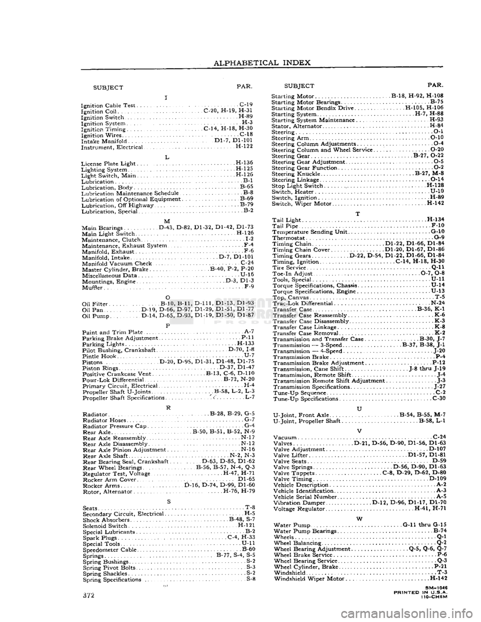
ALPHABETICAL
INDEX
SUBJECT
PAR.
SUBJECT
PAR.
Ignition Cable Test C-l9 Ignition
Coil
C-20, H-19, H-31
Ignition Switch H-89 Ignition System H-3
Ignition
Timing
C-14, H-18, H-30 Ignition Wires C-18
Intake Manifold '." Dl-7, Dl-101
Instrument, Electrical H-122
L
License Plate Light H-l36
Lighting
System H-l25
Light
Switch, Main . H-l 26
Lubrication
B-l
Lubrication,
Body B-65
Lubrication
Maintenance Schedule B-8
Lubrication
of Optional Equipment B-69
Lubrication,
Off Highway B-79
Lubrication,
Special. B-2
M
Main
Bearings D-43, D-82, Dl-32, Dl-42, Dl-73
Main
Light Switch. H-l26
Maintenance, Clutch 1-2 Maintenance, Exhaust System.,
-
F-4
Manifold, Exhaust -F-6 Manifold, Intake D-7, Dl-101
Manifold Vacuum Check. .C-24 Master Cylinder, Brake B-40, P-2, P-20
Miscellaneous Data U-16 Mountings, Engine • • •
-
D-3, Dl-3
Muffler. F-9
O
Oil
Filter B-10, B-ll,
D-lll,
Dl-13, Dl-93
Oil
Pan D-19, D-66, D-97, Dl-29, Dl-51, Dl-77
Oil
Pump. D-14, D-65, D-93, Dl-19, Dl-50, Dl-87
P
Paint and
Trim
Plate • • A-7
Parking
Brake Adjustment P-ll
Parking
Lights H-133
Pilot Bushing, Crankshaft D-70, 1-8
Pintle Hook U-7
Pistons D-20, D-95, Dl-31, Dl-48, Dl-75 Piston Rings. • • •
•
D-37, Dl-47 Positive Crankcase Vent. B-13, C-6, D-110
Powr-Lok
Differential B-72, N-20
Primary
Circuit,
Electrical H-4 Propeller Shaft U-Joints .B-58, L-2, L-3 Propeller Shaft Specifications <:' L-7
R
Radiator
B-28, B-29, G-5
Radiator
Hoses. G-7
Radiator
Pressure Cap G-4
Rear
Axle. B-50, B-51, B-52, N-9
Rear
Axle Reassembly • N-l
7
Rear
Axle Disassembly N-l
2
Rear
Axle Pinion Adjustment N-l6
Rear
Axle Shaft N-2, N-3
Rear
Bearing Seal, Crankshaft D-63, D-85, Dl-62
Rear
Wheel Bearings B-56, B-57, N-4, Q-3
Regulator Test, Voltage H-47, H-71
Rocker
Arm Cover.. . Dl-65
Rocker
Arms D-16, D-74, D-99, Dl-60 Rotor, Alternator H-76, H-79
S
Seats
• T-8 Secondary
Circuit,
Electrical H-5
Shock Absorbers B-48, S-7
Solenoid Switch. H-l21 Special Lubricants B-2
Spark
Plugs C-4, H-33
Special Tools • U-ll
Speedometer
Cable B-60 Springs B-77, S-4, S-5
Spring
Bushings S-2
Spring
Pivot Bolts S-3
Spring
Shackles S^2
Spring
Specifications S-8 372 Starting Motor B-18, H-92, H-108
Starting Motor Bearings B-75
Starting Motor Bendix Drive H-105, H-106
Starting System H-7, H-88
Starting System Maintenance H-93 Stator, Alternator H-84
Steering • • •
•
O-l
Steering Arm P-10
Steering Column Adjustments 0-4
Steering Column and Wheel Service O-20 Steering Gear. . B-27, 0-22
Steering Gear Adjustment 0-5
Steering Gear Function 0-2
Steering Knuckle. B-27, M-8 Steering Linkage 0-14
Stop
Light Switch H-128
Switch, Heater U-10 Switch, Ignition H-89
Switch, Wiper Motor H-142
T
Tail
Light . H-134
Tail
Pipe F-10 Temperature Sending Unit G-10
Thermostat G-9
Timing
Chain Dl-22, Dl-66, Dl-84
Timing
Chain Cover Dl-20, Dl-67, Dl-86
Timing
Gears D-22, D-54, Dl-22, Dl-66, Dl-84
Timing,
Ignition. C-14, H-18, H-30
Tire
Service . •
•
Q-l
1
Toe-in Adjust 0-7, 0-8 Tools, Special. . .
........
U-ll Torque Specifications, Chassis U-14
Torque Specifications, Engine .U-13
Top,
Canvas. T-5
Trac-Lok
Differential N-24
Transfer
Case B-36, K-1
Transfer
Case Reassembly K-6
Transfer
Case Disassembly K-3
Transfer
Case Linkage - K-8
Transfer
Case Removal K-2 Transmission and Transfer Case. B-30, J-7 Transmission —
3-Speed
B-37, B-38, J-l
Transmission —
4-Speed
... J-20
Transmission Brake P-4 Transmission Brake Adjustment P-l
2
Transmission,
Cane Shift .J-8 thru J-19
Transmission,
Remote Shift J-4
Transmission Remote Shift Adjustment J-3
Transmission Specifications
-
J-27
Tune-Up
Sequence
C-2
Tune-Up
Specifications C-30
U
U-Joint, Front Axle . . B-54, B-55, M-7
U-Joint, Propeller Shaft B-58, L-l
Vacuum
C-24 Valves D-21, D-56, D-90, Dl-56, Dl-63
Valve
Adjustment D-107
Valve
Lifter Dl-57, Dl-81
Valve
Seats
D-59
Valve
Springs .D-56, D-90, Dl-63
Valve
Tappets C-8, D-29, D-62, D-80
Valve
Timing D-109
Vehicle Description A-2
Vehicle Identification A-3
Vehicle Serial Number. A-5
Vibration
Damper D-l2, D-96, Dl-17, Dl-70 Voltage Regulator. H-41, H-71
W
Water Pump G-ll thru G-15
Water Pump Bearings B-74
Wheels Q-l
Wheel Balancing Q-2 Wheel Bearing Adjustment Q-5, Q-6, Q-7
Wheel Brake Service P-6 Wheel Bearing Service Q-3
Wheel Cylinder, Brake P-21 Windshield T-3 Windshield Wiper Motor . .H-142
SM-1046
PRINTED
IN U.S.A.
110-CH6M