headlights JEEP CJ 1953 Service Manual
[x] Cancel search | Manufacturer: JEEP, Model Year: 1953, Model line: CJ, Model: JEEP CJ 1953Pages: 376, PDF Size: 19.96 MB
Page 7 of 376
'Jeep*
UNIVERSAL SERIES
SERVICE
MANUAL
B
LUBRICATION
AND
PERIODIC SERVICES
Contents
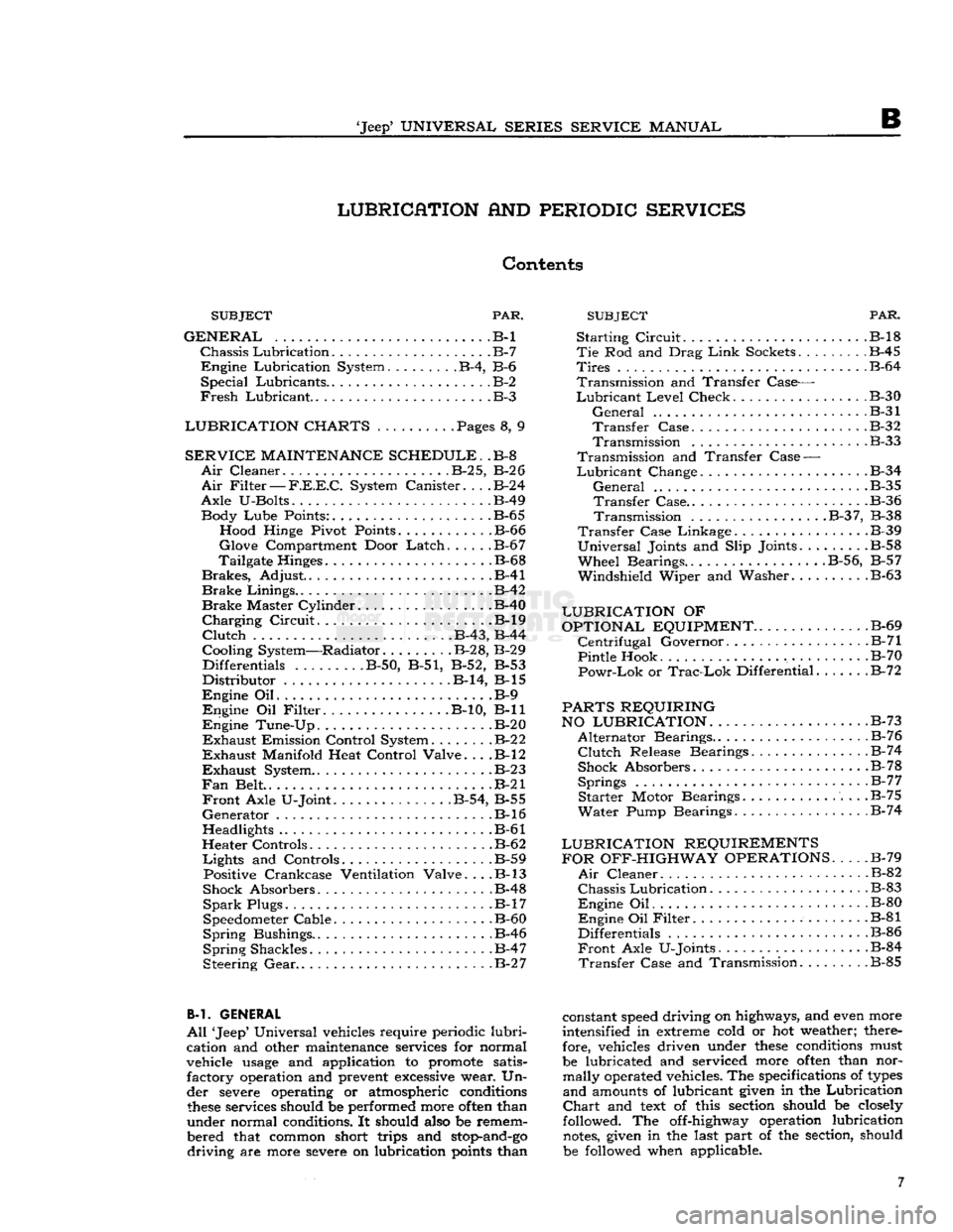
PAR. SUBJECT
PAR.
SUBJECT
GENERAL
.B-l
Chassis
Lubrication
B-7
Engine
Lubrication System B-4, B-6
Special
Lubricants B-2
Fresh
Lubricant.
.B-3
LUBRICATION CHARTS
. Pages 8, 9
SERVICE
MAINTENANCE SCHEDULE.
.B-8
Air
Cleaner
B-2
5,
B-2
6
Air
Filter
—
F.E.E.C.
System Canister
B-2
4
Axle
U-Bolts B-49 Body
Lube
Points: B-65 Hood Hinge Pivot Points B-66
Glove
Compartment Door
Latch
B-6
7
Tailgate Hinges .B-68
Brakes,
Adjust .B-41
Brake
Linings .B-42
Brake
Master Cylinder B-40
Charging
Circuit
B-l9
Clutch
. B-43, B-44
Cooling System—Radiator. B-28, B-29 Differentials
........
.B-50, B-51, B-52, B-53
Distributor
B-14, B-l5
Engine
Oil B-9
Engine
Oil
Filter
B-10, B-ll
Engine
Tune-Up B-20
Exhaust
Emission Control System
B-2
2
Exhaust
Manifold Heat Control Valve. . . .B-l2
Exhaust
System
B-2 3
Fan
Belt . .B-21
Front
Axle U-Joint B-54, B-55
Generator
.B-16
Headlights B-61
Heater Controls B-62
Lights
and Controls B-59 Positive Crankcase Ventilation Valve. . . .B-l3
Shock Absorbers B-48
Spark
Plugs. B-17
Speedometer Cable. .B-60
Spring
Bushings.. . .B-46
Spring
Shackles .B-47
Steering
Gear
B-2 7
B-l. GENERAL
All
'Jeep' Universal vehicles require periodic
lubri
cation and other maintenance services for normal
vehicle
usage
and application to promote satis factory operation and prevent
excessive
wear. Un
der severe operating or atmospheric conditions
these
services should be performed more
often
than
under normal conditions. It should also be remem
bered that common short trips and
stop-and-go
driving
are more severe on lubrication
points
than
Starting
Circuit
B-l8
Tie
Rod and Drag
Link
Sockets
.
B-45
Tires
B-64
Transmission
and Transfer Case—
Lubricant
Level
Check B-30
General
B-31
Transfer
Case B-32
Transmission
.B-33
Transmission
and Transfer
Case
—
Lubricant
Change .B-34
General
.B-35
Transfer
Case B-36
Transmission
B-3
7, B-38
Transfer
Case Linkage B-39
Universal
Joints and Slip Joints.
.......
.B-58
Wheel
Bearings..
.........
. . .B-56, B-57
Windshield
Wiper and Washer B-63
LUBRICATION
OF
OPTIONAL EQUIPMENT
B-69
Centrifugal
Governor. .B-71
Pintle Hook .B-70
Powr-Lok
or
Trac-Lok
Differential B-72
PARTS REQUIRING
NO LUBRICATION.
. . .B-73
Alternator
Bearings. B-76
Clutch
Release Bearings.
.............
.B-74
Shock Absorbers B-78
Springs
B-7
7
Starter
Motor Bearings B-75
Water
Pump Bearings B-74
LUBRICATION REQUIREMENTS FOR OFF-HIGHWAY OPERATIONS
B-79
Air
Cleaner B-82
Chassis
Lubrication
B-83
Engine
Oil B-80
Engine
Oil
Filter
B-81
Differentials .B-86
Front
Axle U-Joints. B-84
Transfer
Case and Transmission .B-85
constant
speed
driving on highways, and even more
intensified in extreme cold or hot weather; there fore, vehicles driven under
these
conditions must
be lubricated and serviced more
often
than nor mally operated vehicles. The specifications of
types
and
amounts of lubricant given in the Lubrication
Chart
and
text
of this section should be closely
followed. The off-highway operation lubrication
notes,
given in the last part of the section, should
be followed when applicable. 7
Page 12 of 376
B
LUBRICATION B-3.
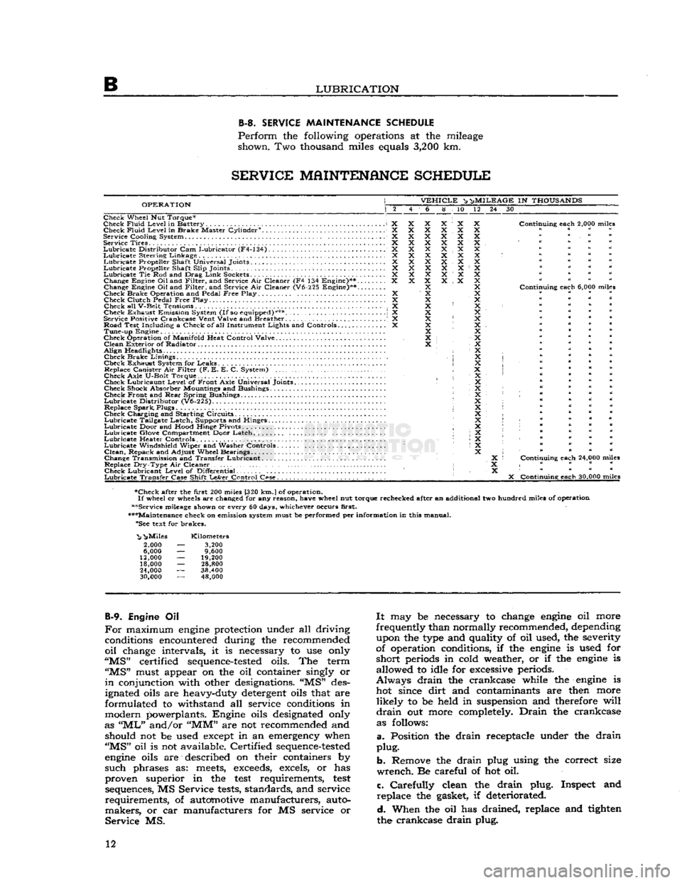
SERVICE
MAINTENANCE
SCHEDULE
Perform
the following operations at the mileage shown. Two thousand miles equals
3,200
km.
SERVICE
MAINTENANCE
SCHEDULE
OPERATION
VEHICLE
^ n>
MILEAGE
IN
THOUSANDS
6 8 10 12 24 30
Check Wheel Nut Torque*
Check
Fluid
Level
in Battery X Check
Fluid
Level
in Brake Master Cylinder0. X
Service
Cooling
System X Service Tires X
Lubricate
Distributor
Cam Lubricator (F4-134) X
Lubricate
Steering Linkage X
Lubricate
Propeller Shaft Universal Joints X
Lubricate
Propeller Shaft
Slip
Joints ; X
Lubricate
Tie Rod and Drag
Link
Sockets................................... X Change Engine
Oil
and
Filter,
and Service Air Cleaner (F4 134 Engine)** X
Change Engine Oil and
Filter,
and Service Air Cleaner (V6-225 Engine)**....
Check Brake Operation and Pedal
Free
Play X Check
Clutch
Pedal
Free
Play. .... X
Check all
V-Belt
Tensions X
Check Exhaust Emission System
(If
so equipped)*** \ X
Service Positive
Crankcase
Vent
Valve
and Breather . .' X
Road Test
Including
a Check of all Instrument
Lights
and Controls X Tune-up Engine
Check Operation of
Manifold
Heat
Control
Valve
Clean
Exterior of Radiator
Align
Headlights • Check Brake
Linings
,
Check Exhaust System for Leaks Replace Canister Air
Filter
(F. E. E. C. System)
Check
Axle
U-Bolt
Torque. Check Lubricaunt
Level
of Front
Axle
Universal Joints
Check Shock Absorber Mountings and Bushings Check Front and
Rear
Spring Bushings
Lubricate
Distributor
(V6-225).
Replace Spark, Plugs
Check Charging and Starting Circuits
Lubricate
Tailgate Latch, Supports and Hinges.
Lubricate
Door and
Hood
Hinge Pivots ;
Lubricate
Glove Compartment Door Latch
Lubricate
Heater Controls •
Lubricate
Windshield
Wiper and Washer Controls
Clean,
Repack and
Adjust
Wheel Bearings
Change Transmission and Transfer Lubricant. .
Replace
Dry-Type
Air Cleaner • Check Lubricant
Level
of
Differential
Lubricate
Transfer
Case
Shift
LeArer
Control
C«se.
. , . . . . . . . .
Continuing
each
2,000 miles
Continuing
each
6,000 miles
Continuing
each
24,000 miles
X
Continuing
each
30,000 miles
•Check after the
first
200 miles [320
km.
J
of operation.
If
wheel or wheels are changed for any
reason,
have
wheel nut torque rechecked after an additional two hundred miles of operation
••Service mileage shown or every 60 days, whichever occurs
first.
•••Maintenance check on emission system must be performed per
information
in this manual. "See text for brakes.
"Nj
^Miles
2,000
6,000
12,000
18,000
24,000
30,000
Kilometers
3,200
9,600
19,200
28,800
38,400 48,000
B-9.
Engine Oil
For
maximum
engine
protection under all driving conditions encountered during the recommended
oil
change intervals, it is necessary to use only
"MS"
certified
sequence-tested
oils. The term
"MS"
must appear on the oil container singly or
in
conjunction with other designations. "MS" des
ignated oils are heavy-duty detergent oils that are
formulated to withstand all service conditions in
modern powerplants. Engine oils designated only
as
"ML"
and/or
"MM"
are not recommended and should not be used except in an emergency when
"MS"
oil is not available. Certified
sequence-tested
engine
oils are described on their containers by
such
phrases as:
meets,
exceeds,
excels, or has
proven superior in the
test
requirements,
test
sequences, MS Service
tests,
standards, and service
requirements,
of automotive manufacturers, auto
makers,
or car manufacturers for MS service or
Service
MS.
It
may be necessary to change
engine
oil more
frequently than normally recommended, depending upon the type and quality of oil used, the severity
of operation conditions, if the
engine
is used for
short
periods in cold weather, or if the
engine
is allowed to idle for excessive periods.
Always
drain
the crankcase while the
engine
is hot since
dirt
and contaminants are then more
likely
to be held in suspension and therefore
will
drain
out more completely.
Drain
the crankcase as follows:
a.
Position the
drain
receptacle under the
drain
plug.
b.
Remove the
drain
plug using the correct size
wrench.
Be careful of hot oil.
c.
Carefully
clean the
drain
plug. Inspect and
replace
the gasket, if deteriorated.
d.
When the oil has drained, replace and tighten
the crankcase
drain
plug. 12
Page 17 of 376
'Jeep'
UNIVERSAL SERIES SERVICE
MANUAL
B
Reinstall
the axle shafts, and
refill
the housings to
plug level using the universal joint lubricant
specified in
Lubrication
Specifications.
B-56.
Front
Axle Wheel Bearings
To
lubricate the wheel bearings, it is necessary
to remove, clean, repack, and adjust them. When
front wheel hubs and bearings are removed for
lubrication,
they should be thoroughly washed in a
suitable cleaning solvent. The bearings should be
carefully
dried and then given a thorough cleaning
and
inspection. Use a clean brush to remove all
particles
of old lubricant from bearings and hubs.
After
the bearings are cleaned, inspect them for
pitted races and rollers. Also, check the hub oil
seals.
Note:
Wheel bearing lithium base lubricants are
used at the factory for
initial
fill
of
these
bearings.
When
lithium base and sodium base lubricants are
mixed,
the result is a thinned-out mixture that
can
bleed through seals. It is therefore important
that lubricants with the correct base be used when
lubricating
the wheel bearings.
Should
leaks occur at wheel bearing seals, the leaks
may
be caused by a mixture of two
types
of
lubri
cants.
In such cases, the old lubricant should be
completely removed before new lubricant is added.
Wheel
bearings should be thoroughly cleaned,
lubricated
with lithium base and reinstalled.
Repack
the bearing
cones
and rollers with grease
and
reassemble hub in the reverse order of the
disassembly. Test the bearing adjustment as out
lined
in Section Q.
B-57.
Rear
Axle Wheel Bearings
The
Rear
wheel bearings an early models equipped
with
lubrication fittings with a vent opening
through the housings above each fitting should be
lubricated
sparingly, each
2,000
miles
[3.200
km.].
Use
a hand compressor and wheel bearing grease,
forcing
the grease through each lubrication fitting
until
it flows from the vent. Vent should be kept
clear
of obstruction or grease
will
back up into the
brakes.
Do not add grease after it flows from the
vent for it may be forced through the wheel key-
way
onto
the outside of the wheel and possibly
onto
the brake linings.
Rear
wheel bearings that do
not have lubrication fittings should be removed
each
12,000
miles
[19.200
km.] and the bearing
cleaned, inspected and repacked. Refer to proce
dure
in Par. B-56.
Note:
When servicing the Flanged Axle Unit
Bear
ing Assembly, refer to Section N, Par. N-5 for
proper
lubrication procedures.
B-58.
Propeller Shafts
and
Universal Joints
The
propeller shaft slip joints and universals should
be lubricated with a hand compressor grease gun so as to not damage the bearing seals. The units
should be lubricated with a
good
quality grease.
Refer
to the
Lubrication
Chart
for lubrication fre
quency and lubricant type and grade. B-59.
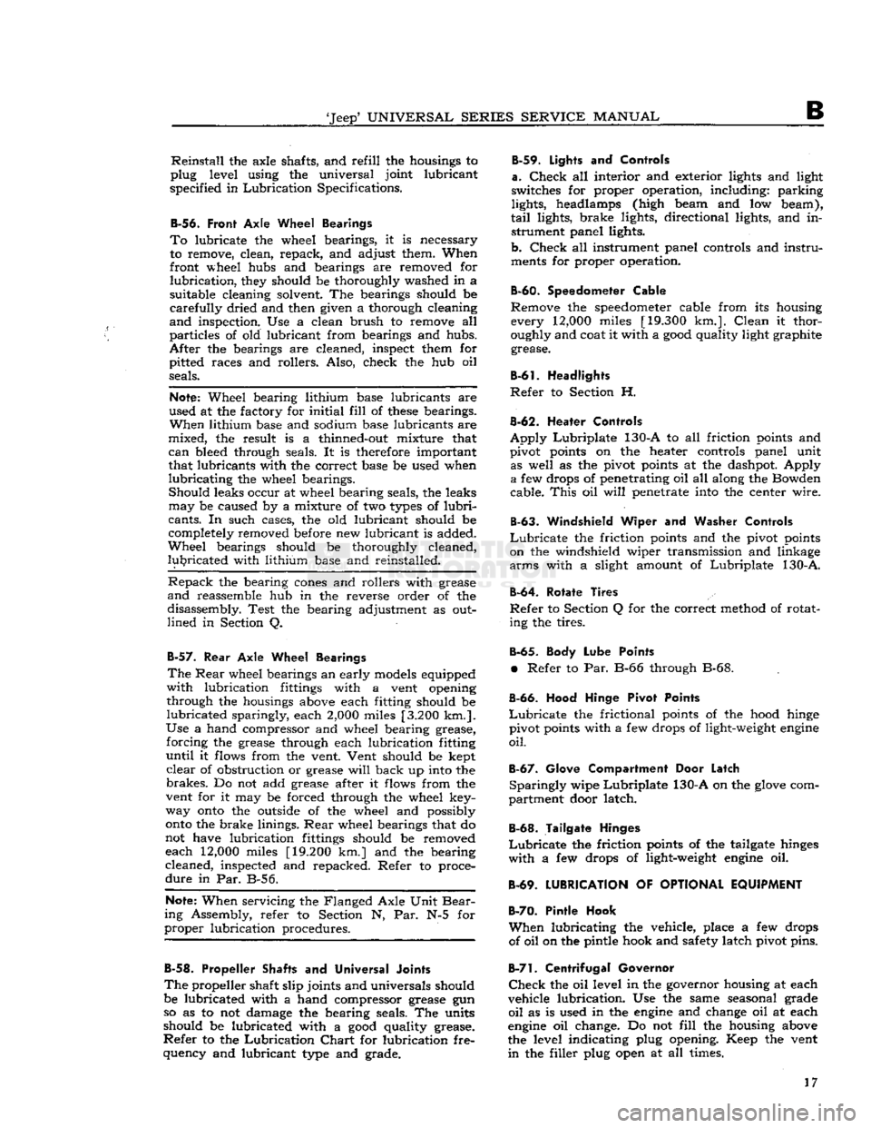
Lights
and
Controls
a.
Check
all interior and exterior lights and light
switches for proper operation, including: parking
lights, headlamps (high beam and low beam),
tail
lights, brake lights, directional lights, and in strument panel lights.
b.
Check
all instrument panel controls and
instru
ments for proper operation.
B-60.
Speedometer Cable
Remove the
speedometer
cable from its housing every
12,000
miles
[19.300
km.].
Clean
it thor
oughly and coat it with a
good
quality light graphite grease.
B-61.
Headlights
Refer
to Section H.
B-62.
Heater Controls
Apply
Lubriplate
130-A to all friction points and
pivot points on the heater controls panel unit as well as the pivot points at the dashpot. Apply
a
few drops of penetrating oil all along the Bowden
cable.
This
oil
will
penetrate into the center wire.
B-63.
Windshield Wiper and
Washer Controls
Lubricate
the friction points and the pivot points
on the windshield wiper transmission and linkage
arms
with a slight amount of
Lubriplate
130-A.
B-64.
Rotate Tires
Refer
to Section Q for the correct method of rotat ing the tires.
B-65.
Body Lube Points
•
Refer to Par. B-66 through B-68.
B-66.
Hood Hinge Pivot Points
Lubricate
the frictional points of the hood hinge
pivot points with a few drops of light-weight
engine
oil.
B-67.
Glove Compartment Door Latch
Sparingly
wipe
Lubriplate
130-A on the
glove
com
partment door latch.
B-68.
Tailgate Hinges
Lubricate
the friction points of the tailgate hinges
with
a few drops of light-weight
engine
oil.
B-69.
LUBRICATION
OF
OPTIONAL EQUIPMENT
B-70.
Pintle Hook
When
lubricating the vehicle, place a few drops of oil on the pintle hook and safety latch pivot pins.
B-7!.
Centrifugal Governor
Check
the oil level in the governor housing at each
vehicle lubrication. Use the same seasonal grade
oil
as is used in the
engine
and change oil at each
engine
oil change. Do not
fill
the housing above
the level indicating plug opening. Keep the vent
in
the filler plug open at all times. 17
Page 174 of 376
H
ELECTRICAL
SYSTEM
the condenser. Replace the condenser. If there is
no jump to full voltage, overhaul or replace the
distributor.
k.
With the points closed, connect the voltmeter
from
a clean, paint-free
post
on the distributor
body to the negative
post
of the battery. The volt
age drop should be practically zero, a hardly
readable deflection on the voltmeter. If the volt meter registers a
voltage
drop, perform the checks
in
steps
1
and m following.
I.
Check
for
voltage
drop in the battery ground
cable.
Clean
the battery
post,
cable terminals, and contact surface on the bellhousing, or on body if
a
noticeable deflection of the voltmeter occurs,
m.
Check
for any
voltage
drop
between
the dis
tributor
body and a clean, paint-free
spot
on the
cylinder
block. If there is any
voltage
drop, remove
the distributor and clean the mounting surfaces of
distributor
body and cylinder block.
H-5.
SECONDARY
CIRCUIT
If
satisfactory ignition is not obtainable with cor
rect
point gap and tension; satisfactory condenser;
sufficient primary voltage; and correctly cleaned, gapped, and installed spark plugs; the secondary
circiut
should be investigated.
a.
Test the coil.
Bring
the coil up to operating
temperature using the coil heat feature of a coil tester, if available. Refer to the coil tester manu
facturer's
instructions for specific hook-ups for
performing the checks given in
steps
b, c, and d following.
b. Connect the positive lead of the tester to the
battery terminal of the coil primary winding.
Con
nect the tester ground lead to the coil tower. Mea
sure
the resistance of the secondary winding. If the
resistance is more than
20,000
ohms, a fault in the
secondary winding is indicated.
c.
Check
for a grounded secondary by touching the tester ground lead to the coil cover. If resistance
is not over
100,000
ohms, the secondary is grounded
to the cover.
d.
If the secondary winding is satisfactory, mea
sure
the primary current draw in accordance with
the instructions of the
test
equipment manu
facturer.
e.
Check
the secondary circuit for leakage. With the coil primary in the circuit with the breaker unit of the tester, connect a long, high-tension
test
lead
to the coil tower.
Check
the secondary circuit for
leakage by performing the checks given in
steps
f. g, h, and i following.
Note:
In the following
tests,
a slight sparking and
meter deflection
will
usually be
seen
just as contact
is made.
This
is caused by capacitance and
does
not
indicate defective insulation.
f.
Check
distributor cap. Remove the coil lead from the cap and touch the
test
lead to the center contact
inside the cap. If the meter reading drops when the contact is touched or if sparking is seen, a leakage
path is present
between
the center contact and one
of the plug towers.
This
leakage path
will
be in the
form
of a
crack
or carbon track in the cap. Discon nect the spark plug wires from the cap one at a
time and
test
each plug contact with the high-
voltage
lead and with all other plug wires con
nected. Any sparking or meter drop indicates that
a
leakage path exists
between
that particular con
tact and an adjacent one. Testing the adjacent contacts
will
determine which pair is at fault,
g-
Check
distributor rotor. Touch the
test
lead to
the spring contact in the center of the distributor
rotor.
Any leakage in the rotor insulation
between
the contact and the shaft
will
cause a drop in the meter reading and usually sparking
will
be seen.
h.
Check
spark plug wires. Disconnect the spark
plug wires from the plugs and
test
the plug terminal of each. The meter reading should not drop below
the open secondary value (value before making contact). If it
does
or if a large spark occurs when
the
test
lead and the plug wire are separated, there
is a break in the insulation on that wire.
i.
Check
the coil tower insulation. Remove the
high-tension
test
lead from the coil tower and touch
the ground lead of the coil tester to several points
around
the base of the tower. Any sparking or deflection of the meter indicates a leakage path in
the tower insulation.
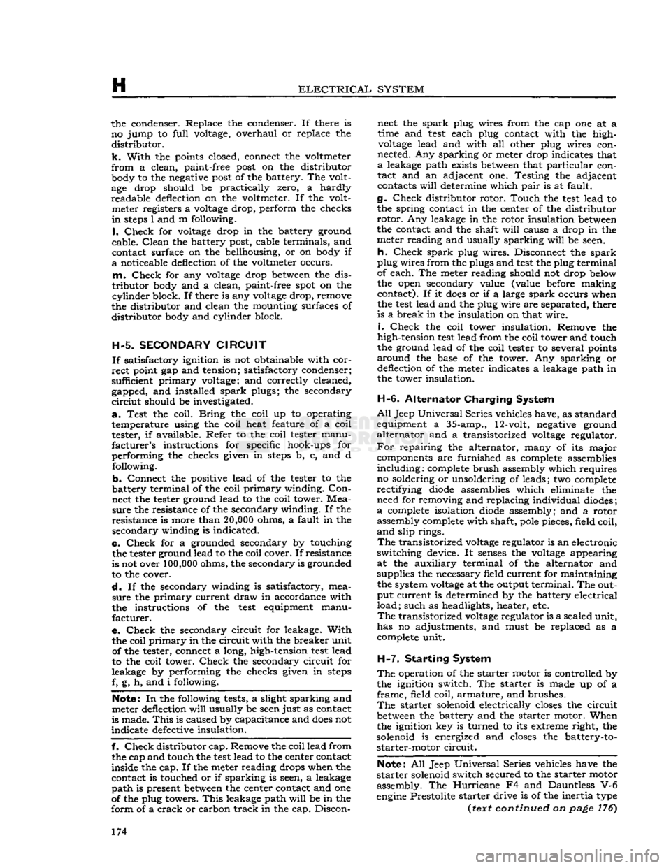
H-6.
Alternator Charging System
All
Jeep
Universal
Series vehicles have, as standard
equipment a 35-amp., 12-volt, negative ground
alternator and a transistorized
voltage
regulator.
For
repairing the alternator, many of its major components are furnished as complete assemblies
including:
complete brush assembly which requires no soldering or unsoldering of leads; two complete
rectifying
diode
assemblies which eliminate the need for removing and replacing individual diodes;
a
complete isolation
diode
assembly; and a rotor assembly complete with shaft,
pole
pieces, field coil,
and
slip rings.
The
transistorized
voltage
regulator is an electronic
switching device. It
senses
the
voltage
appearing at the auxiliary terminal of the alternator and
supplies the necessary field current for maintaining the system
voltage
at the output
terminal.
The out
put current is determined by the battery electrical
load;
such as headlights, heater, etc.
The
transistorized
voltage
regulator is a sealed unit,
has no adjustments, and must be replaced as a
complete unit.
H-7.
Starting System
The
operation of the starter motor is controlled by
the ignition switch. The starter is made up of a
frame,
field coil, armature, and brushes.
The
starter solenoid electrically
closes
the circuit
between
the battery and the starter motor. When the ignition key is turned to its extreme right, the
solenoid is energized and
closes
the battery-to- starter-motor circuit.
Note:
All Jeep Universal Series vehicles have the
starter
solenoid switch secured to the starter motor
assembly. The Hurricane F4 and Dauntless V-6
engine
Prestolite starter drive is of the inertia type
(rexr
continued on
page
176) 174
Page 195 of 376
'Jeep*
UNIVERSAL
SERIES SERVICE
MANUAL
H
no soldering or unsoldering of leads; two complete
rectifying
diode assemblies
which
eliminate the need
for removing and replacing individual diodes; a
corpplete isolation diode assembly; and a rotor
assembly complete with shaft,
pole
pieces, field
coil,
and slip rings.
The
transistorized
voltage
regulator is an electronic
switching device. It
senses
the
voltage
appearing
at the auxiliary terminal of the alternator and
supplies the necessary field current for maintaining
the system
voltage
at the output terminal. The
output current is determined by the battery electri
cal
load; such as headlights, heater, etc.
The
transistorized
voltage
regulator is a sealed
unit,
has no adjustments, and must be replaced
as a complete unit.
H-64. ALTERNATOR
PRECAUTIONS
The
following precautions must be observed to
prevent damage to the alternator and regulator.
a.
Never reverse battery connections. Always
check
the battery polarity with a voltmeter before
any
connections are made to be sure that all con
nections correspond to the battery ground polarity of the vehicle.
b.
Booster batteries for starting must be properly
connected. Make sure that the negative cable of
the booster battery is connected to the negative
terminal
of the battery in the vehicle. The positive
cable of the booster battery should be connected
to the positive terminal of the battery in the
vehicle.
c.
Disconnect the battery cables before using a fast charger.
d.
Never use a fast charger as a booster for
starting
the vehicle.
e.
Never disconnect the
voltage
regulator while
the
engine
is running.
f.
Do not ground the alternator output terminal.
g.
Do not operate the alternator on an open
circuit
with
the field energized.
h.
Do not attempt to polarize an alternator.
These
precautions are stated here as an aid to
service
personnel. They are also restated at appro
priate
places in the
text
of this section of the
manual.
H-65. ALTERNATOR
CHARGING
SYSTEM SERVICE
Important:
All alternator
tests
for the 35, 40 and
55 amp alternator are the same, however, there is a
difference
between
the location of the various ter
minals
and field current specifications. The field
current
of the 35 amp alternator should be 1.7 to 2.3 amps, 40 and 55 amp alternators should be 1.8
to 2.4 amps, with
full
battery
voltage
applied to
the filed coil. Disassembly and assembly procedures
are
the same for all three alternators.
Terminal
locations and wire harness color
codes
for the 35,
40 and 55 amp alternator are shown in Fig. H-38.
H-66.
Service Diagnosis
In
diagnosing a suspected malfunction of the
alternator
charging system, consideration must
be given to the complete electrical power plant of the vehicle; including the alternator, regulator,
ignition switch, charge indicator lamp, battery,
and
all associated wiring. If it is suspected that the
alternator
is not fully charging the battery and
fulfilling
the electrical requirements of the electrical
system, several checks should be made before
checking
the alternator itself:
Note:
Whenever service is required in connection
with
an alternator problem, the first
step
should be to verify that the wiring harness hook-up is correct
as indicated in Fig. H-38.
a.
Test the condition of the battery and
state
of
charge
(Par. H-2).
If the battery is not fully charged
and
in
good
condition, use a replacement battery
for making alternator system
tests.
Caution:
Make certain that the negative battery
post
is connected to ground when making the
battery installation. Serious damage to the alter
nator
can result if battery polarity is reversed.
b.
Check
fan belt for proper tension (Par.
C-27).
Caution:
To increase belt tension, apply pressure
to alternator front housing only as permanent damage can result if pressure is applied to
rear
housing.
H-67.
Alternator In Vehicle Tests
The
following
tests
are made with the alternator
in
the vehicle with output and regulator connec
tions maintained to the alternator except as noted
in
Fig. H-27 and H-28. The field plug and
voltage
regulator are disconnected for
these
tests.
The
tests
are given in proper order and detail in the
following paragraphs.
a.
Isolation Diode Test: To determine if the isola
tion diode is open or shorted, refer to Par. H-69.
b.
Alternator Output Test: To isolate the trouble
to the alternator or regulator, refer to Par. H-70.
c.
Alternator
Field
Circuit
Test: To determine the condition of the field
circuit
(brushes and rotor),
refer
to Par. H-73.
d.
Brush
Insulation
and Continuity
Test:
To deter
mine the condition of the
brush,
refer to
Par.
H-75.
e.
Rotor In-Vehicle Test: To determine whether
the rotor coil is open or shorted, refer to
Par.
H-73.
f. Any further
tests
must be conducted with the
alternator
removed and disassembled. When this
is done, the condition of the rotor, the rectifying
and
isolation diodes, and the stator can be further
tested.
A
commercial alternator tester Sun
Electric
Model
VAT-20
or equivalent can be used to make all
necessary
tests
on the alternator system. If a com
mercial
tester is used, follow the recommended
testing procedure outlined by the tester manu
facturer.
If
a commercial tester is not available, follow the
testing procedure as outlined in this manual.
H-68.
Test Equipment
a.
Volt Ampere Tester such as Sun
Electric
Model
VAT-20
or equivalent with meter ranges as shown
in
the following list can be used. 195
Page 212 of 376
H
ELECTRICAL
SYSTEM
H-124. Testing Indicators and Gauges
Two
gauges
(fuel and temperature) and two in dicators (oil pressure and battery charge) that are
located in the instrument cluster are electrically operated.
The
fuel
gauge
is connected by a single wire to a
float-and-slide-rheostat sending unit in the fuel
tank.
The
temperature
gauge
is connected by a single
wire
to a resistance-type sending unit mounted on the engine.
The
battery charge indicator operates when there
is a difference in potential
between
the generator
and
the battery
.The
battery charge indicator lights
when the generator is not charging the battery. The
indicator
light
goes
out when the generator
begins
to charge the battery.
The
oil pressure indicator is connected by a single
wire
to a diaphragm switch located on the engine.
When
engine
oil pressure is low or zero and the
ignition switch is on, the oil pressure indicator
will
light. When
engine
speed is increased slightly above idle speed, raising the oil pressure to approximately 6 psi. [0,2 kg-cm2], the diaphragm switch
will
open the circuit and the indicator light
will
go out.
A
voltage
regulator maintains a constant
voltage
to the
gauges
in normal operation. On early vehicles,
this
voltage
regulator was mounted on the
rear
of
the instrument cluster. On current vehicles, the
voltage
regulator is integral with the fuel
gauge.
Should
trouble
develop
in the
gauges,
first check the regulator (fuel
gauge
on current production vehicle). If the
voltage
to the regulator is below 10 volts system low
gauge
readings
will
result.
Voltage in
excess
of 16 volts
will
not affect
gauge
readings but may result in premature wear of the
regulator contacts. If the
voltage
to the regulator is
within
the above limits, check the electrical con nections to the regulator (or fuel gauge), especially
the ground connection. If the readings of all the
gauges
is too high, or they all read too low, replace
the regulator (or fuel gauge).
If
the temperature
gauge
or heat indicator in the
instrument cluster have failed, the cause may
originate from the jumper bar shorting out against the instrument case.
Check
the jumper bar
between
the temperature
gauge
and heat indicator at the
rear
of the instrument case. On later production vehicles, the jumper bar is covered with an in
sulating
sleeve
to protect it from shorting out
against the instrument case. If the jumper bar
does
not have this
sleeve,
either install one or
wrap
the bar with plastic electrical tape to
half
an
inch [12,7 mm.] from each end. When installing the jumper bar, be sure the curved
segment
is
closest to the fuel
gauge.
Should
only one of the two
gauges
register incor
rectly,
check the lead wire from the
gauge
to the
sending unit for shorts or open connections. Next disconnect the
gauge
from the sending unit, and
connect the
gauge
to a new fuel tank sending unit
which
has been grounded to the vehicle.
If
the
gauge
registers incorrectly when operating the new unit,
replace the
gauge;
if correctly, replace the sending
unit.
Should
a new fuel tank unit not be available for testing, use a 12-volt
test
light in its place. When
the
gauge
is operating correctly, the pointer
will
move
approximately three-quarters across the
dial.
On
some
vehicles, the temperature
gauge
may
register on or
close
to the H (hot)
mark
when
coolant temperature is
190°F.
to
200°F.
[88°C.
a
93°C.].
In such cases, a 25-ohm,
1-watt
resistor
may be installed on the temperature
gauge
which
will
place the pointer just beyond the center
mark
at a coolant temperature of
190°F.
to
200°F.
Install
the resistor
between
the two terminals on the back
of the
gauge.
Insulate the
exposed
leads of the resistor with electrical tape.
If
the oil pressure indicator
does
not indicate cor
rectly,
first check the light bulb. Next check all
connections and lead wires. If, after all possible
defects
are corrected, the indicator light
does
not go on and off properly, then the diaphragm type
switch in the cylinder block should be replaced.
H-12S.
LIGHTING SYSTEM The
wiring of the lighting systems is shown in
the wiring diagrams, which indicate the various units in relation to their positions in the vehicle.
The
wires in the various circuits are of different
colors or are marked by tracers to aid when check
ing individual circuits.
The
lighting circuits of all models are protected by
an
overload circuit breaker mounted on the back of the main light switch and no replaceable fuse is
required.
The
upper and lower headlight beams are con
trolled by a
foot
switch located on the toe board
to the left of the clutch pedal.
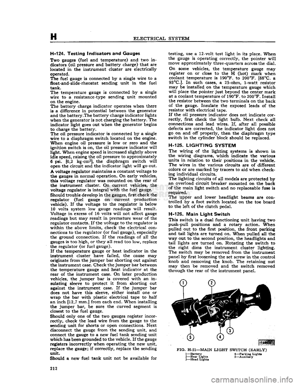
H-126.
Main
Light
Switch
This
switch is a dual functioning unit having two
push-pull
positions and a rotary action. When
pulled out to the first position, the front parking
and
tail
lights are turned on. When pulled all the
way out to the second position, the headlights and
tail
lights are turned on. Rotating the switch to
the right dims the instrument cluster lighting.
The
switch may be removed from the instrument
panel by first loosening the set screw in the control
knob and removing the knob. The retaining nut may then be removed and the switch removed
through the
rear
of the instrument panel.
FIG.
H-51—MAIN
LIGHT
SWITCH
(EARLY)
1—
Battery
4—Parking Lights
2—
Rear
Lights 5—Auxiliary
3—
Head
Lights
212
Page 213 of 376
'Jeep'
UNIVERSAL
SERIES SERVICE
MANUAL
H
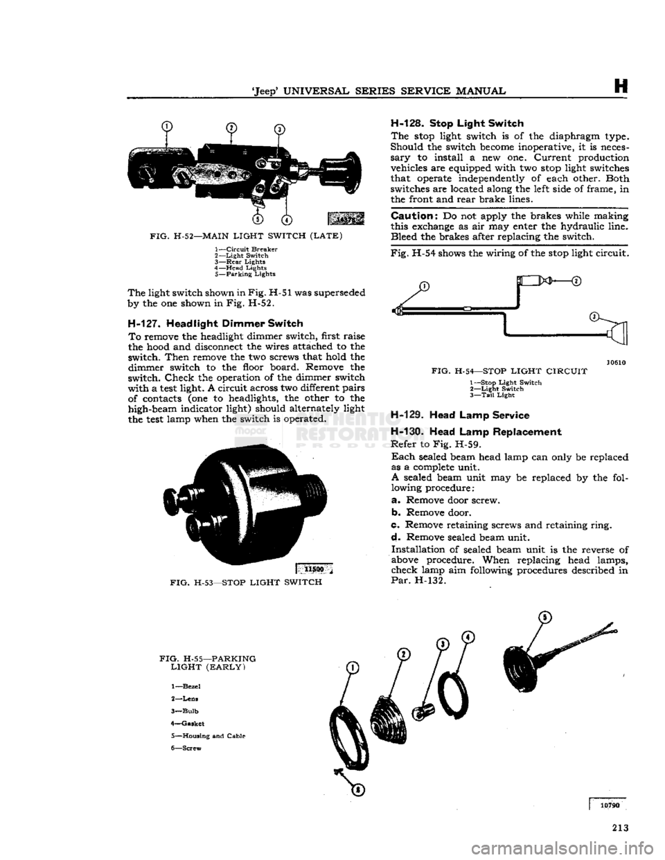
FIG.
H-52—MAIN
LIGHT SWITCH (LATE)
1—
Circuit
Breaker
2—
Light
Switch
3—
Rear
Lights
4—
Head
Lights
5—
Parking
Lights
The
light switch shown in
Fig.
H-51 was superseded
by the one shown in
Fig.
H-52.
H-127.
Headlight Dimmer Switch To
remove the headlight dimmer switch, first raise
the hood and disconnect the wires attached to the
switch.
Then
remove the two screws that hold the
dimmer
switch to the floor board. Remove the
switch.
Check
the operation of the dimmer switch
with
a
test
light. A
circuit
across two different pairs of contacts (one to headlights, the other to the
high-beam indicator light) should alternately light
the
test
lamp when the switch is operated.
H-128.
Stop Light Switch
The
stop
light switch is of the diaphragm type.
Should
the switch
become
inoperative, it is neces
sary
to install a new one.
Current
production vehicles are equipped with two
stop
light switches
that operate independently of each other. Both
switches are located along the
left
side of frame, in the front and
rear
brake lines.
Caution:
Do not apply the brakes while making
this exchange as air may enter the hydraulic line.
Bleed
the brakes after replacing the switch.
Fig.
H-54 shows the wiring of the
stop
light
circuit.
11500
FIG.
H-53—STOP
LIGHT SWITCH
FIG.
H-54—STOP
LIGHT CIRCUIT
1— Stop
Light
Switch
2—
Light
Switch
3—
Tail
Light
H-129. Head Lamp Service
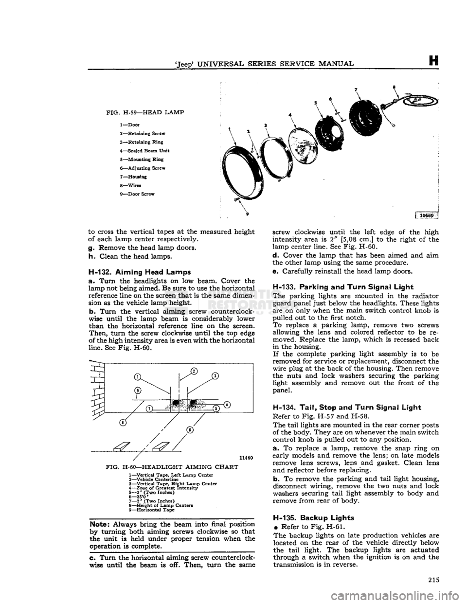
H-130.
Head Lamp Replacement
Refer
to Fig. H-59.
Each
sealed beam head lamp can only be replaced as a
complete
unit.
A
sealed beam unit may be replaced by the fol lowing procedure:
a.
Remove door screw.
b.
Remove door.
c.
Remove retaining screws and retaining
ring.
d.
Remove sealed beam unit.
Installation
of sealed beam unit is the reverse of
above procedure. When replacing head lamps,
check
lamp aim following procedures described in
Par.
H-132.
FIG.
H-55—PARKING
LIGHT (EARLY)
1—
Bezel
2—
Lens
3—
Bulb
4—
Gasket
5—
Housing
and Cable
6—
Screw
213
Page 215 of 376
'Jeep*
UNIVERSAL
SERIES
SERVICE
MANUAL
H
FIG.
H-59—HEAD LAMP
1—
Door
2—
Retaining
Screw
3—
Retaining
Ring
4—
Sealed
Beam
Unit
5—
Mounting
Ring
6—
Adjusting
Screw 7—
Housing
8—
Wires
9—
Door
Screw 310669
to cross the vertical
tapes
at the measured height
of each lamp center respectively.
g.
Remove the head lamp doors.
h.
Clean
the head lamps.
H-132.
Aiming Head Lamps
a.
Turn
the headlights on low beam. Cover the lamp not being aimed. Be sure to use the horizontal reference line on the screen that is the same dimen
sion as the vehicle lamp height.
b.
Turn
the vertical aiming screw counterclock
wise until the lamp beam is considerably lower
than
the horizontal reference line on the screen.
Then,
turn
the screw clockwise until the top
edge
of the high intensity
area
is even with the horizontal
line.
See Fig. H-60.
I
(T)
JT)
1'.'' | '':'
11460
FIG.
H-60—HEADLIGHT AIMING
CHART
1—
Vertical
Tape,
Left
Lamp
Center
2—
Vehicle
Centerline
3—
—Vertical
Tape,
Right
Lamp
Center
4—
Zone
of Greatest Intensity
5—
2
*
(Two Inches)
6— 25'0
'
7—
2
*
(Two Inches)
8—
Height
of
Lamp
Centers
9—
Horizontal
Tape
Note:
Always bring the beam into final position
by turning both aiming screws clockwise so that
the unit is held under proper tension when the operation is complete.
c. Turn
the horizontal aiming screw counterclock
wise until the beam is off.
Then,
turn
the same
screw
clockwise until the
left
edge
of the high
intensity area is 2" [5,08 cm.] to the right of the
lamp center line. See Fig. H-60.
d.
Cover the lamp that has been aimed and aim
the other lamp using the same procedure.
e.
Carefully
reinstall the head lamp doors.
H-133.
Parking
and
Turn Signal Light
The
parking lights are mounted in the radiator
guard
panel just below the headlights. These lights
are
on only when the main switch control knob is
pulled
out to the first notch.
To
replace a parking lamp, remove two screws allowing the lens and colored reflector to be re
moved. Replace the lamp, which is recessed back
in
the housing.
If
the
complete
parking light assembly is to be
removed for service or replacement, disconnect the
wire
plug at the back of the housing.
Then
remove
the nuts and lock washers securing the parking light assembly and remove out the front of the
panel.
H-134. Tail, Stop
and
Turn Signal Light
Refer
to Fig. H-57 and H-58.
The
tail
lights are mounted in the
rear
corner
posts
of the body. They are on whenever the main switch
control
knob is pulled out to any position.
a.
To replace a lamp, remove the snap ring on
early
models
and remove the lens; on late
models
remove lens screws, lens and gasket.
Clean
lens
and
reflector before replacing.
b. To remove the parking and
tail
light housing,
disconnect wiring, remove the two nuts and lock
washers securing
tail
light assembly to body and remove from
rear
of body.
H-135-
Backup Lights •
Refer to Fig. H-61.
The
backup lights on late production vehicles are located on the
rear
of the vehicle directly below
the
tail
light. The backup lights are actuated
through a switch when the ignition is on and the
transmission
is in reverse. 215