stop start JEEP CJ 1953 Service Manual
[x] Cancel search | Manufacturer: JEEP, Model Year: 1953, Model line: CJ, Model: JEEP CJ 1953Pages: 376, PDF Size: 19.96 MB
Page 7 of 376
'Jeep*
UNIVERSAL SERIES
SERVICE
MANUAL
B
LUBRICATION
AND
PERIODIC SERVICES
Contents
PAR. SUBJECT
PAR.
SUBJECT
GENERAL
.B-l
Chassis
Lubrication
B-7
Engine
Lubrication System B-4, B-6
Special
Lubricants B-2
Fresh
Lubricant.
.B-3
LUBRICATION CHARTS
. Pages 8, 9
SERVICE
MAINTENANCE SCHEDULE.
.B-8
Air
Cleaner
B-2
5,
B-2
6
Air
Filter
—
F.E.E.C.
System Canister
B-2
4
Axle
U-Bolts B-49 Body
Lube
Points: B-65 Hood Hinge Pivot Points B-66
Glove
Compartment Door
Latch
B-6
7
Tailgate Hinges .B-68
Brakes,
Adjust .B-41
Brake
Linings .B-42
Brake
Master Cylinder B-40
Charging
Circuit
B-l9
Clutch
. B-43, B-44
Cooling System—Radiator. B-28, B-29 Differentials
........
.B-50, B-51, B-52, B-53
Distributor
B-14, B-l5
Engine
Oil B-9
Engine
Oil
Filter
B-10, B-ll
Engine
Tune-Up B-20
Exhaust
Emission Control System
B-2
2
Exhaust
Manifold Heat Control Valve. . . .B-l2
Exhaust
System
B-2 3
Fan
Belt . .B-21
Front
Axle U-Joint B-54, B-55
Generator
.B-16
Headlights B-61
Heater Controls B-62
Lights
and Controls B-59 Positive Crankcase Ventilation Valve. . . .B-l3
Shock Absorbers B-48
Spark
Plugs. B-17
Speedometer Cable. .B-60
Spring
Bushings.. . .B-46
Spring
Shackles .B-47
Steering
Gear
B-2 7
B-l. GENERAL
All
'Jeep' Universal vehicles require periodic
lubri
cation and other maintenance services for normal
vehicle
usage
and application to promote satis factory operation and prevent
excessive
wear. Un
der severe operating or atmospheric conditions
these
services should be performed more
often
than
under normal conditions. It should also be remem
bered that common short trips and
stop-and-go
driving
are more severe on lubrication
points
than
Starting
Circuit
B-l8
Tie
Rod and Drag
Link
Sockets
.
B-45
Tires
B-64
Transmission
and Transfer Case—
Lubricant
Level
Check B-30
General
B-31
Transfer
Case B-32
Transmission
.B-33
Transmission
and Transfer
Case
—
Lubricant
Change .B-34
General
.B-35
Transfer
Case B-36
Transmission
B-3
7, B-38
Transfer
Case Linkage B-39
Universal
Joints and Slip Joints.
.......
.B-58
Wheel
Bearings..
.........
. . .B-56, B-57
Windshield
Wiper and Washer B-63
LUBRICATION
OF
OPTIONAL EQUIPMENT
B-69
Centrifugal
Governor. .B-71
Pintle Hook .B-70
Powr-Lok
or
Trac-Lok
Differential B-72
PARTS REQUIRING
NO LUBRICATION.
. . .B-73
Alternator
Bearings. B-76
Clutch
Release Bearings.
.............
.B-74
Shock Absorbers B-78
Springs
B-7
7
Starter
Motor Bearings B-75
Water
Pump Bearings B-74
LUBRICATION REQUIREMENTS FOR OFF-HIGHWAY OPERATIONS
B-79
Air
Cleaner B-82
Chassis
Lubrication
B-83
Engine
Oil B-80
Engine
Oil
Filter
B-81
Differentials .B-86
Front
Axle U-Joints. B-84
Transfer
Case and Transmission .B-85
constant
speed
driving on highways, and even more
intensified in extreme cold or hot weather; there fore, vehicles driven under
these
conditions must
be lubricated and serviced more
often
than nor mally operated vehicles. The specifications of
types
and
amounts of lubricant given in the Lubrication
Chart
and
text
of this section should be closely
followed. The off-highway operation lubrication
notes,
given in the last part of the section, should
be followed when applicable. 7
Page 10 of 376
B
LUBRICATION
B-2.
Special Lubricants
Special
lubricants are required for certain
lubri
cation points on the 'Jeep' Universal vehicles. The
special
lubricants are necessary for proper function ing and maintenance of the vehicle. The
Lubrica
tion
Chart
(Fig. B-l and B-2)
designates
the spe
cial
lubricating points and identifies them by type
or
part number.
B-3.
Applying
Fresh
Lubricant
When
servicing or lubricating the vehicle, it is important that all old lubricant and
dirt
be re moved from the fitting and/or plugs before servic
ing and that the recommended type of lubricant be used for the particular item being serviced.
Force
lubricant through the lube fittings until the lubricant being forced out of the joint is fresh
lubricant,
indicating that all old lubricant has
been removed.
B-4.
Engine
Lubrication
System —
Hurricane
F4 Engine
•
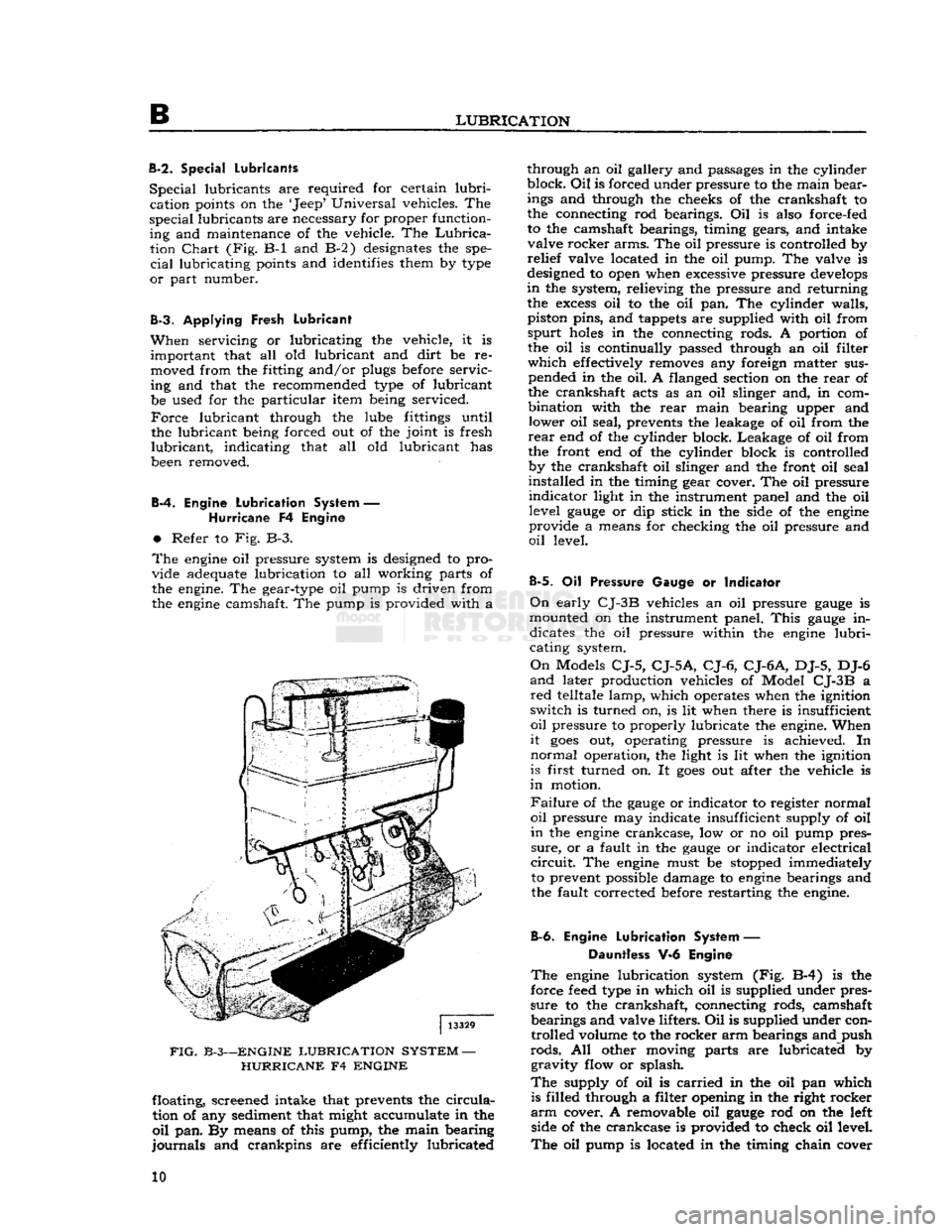
Refer to Fig. B-3.
The
engine
oil pressure system is designed to pro
vide adequate lubrication to all working parts of
the engine. The gear-type oil pump is driven from
the
engine
camshaft. The pump is provided with a
FIG.
B-3—ENGINE
LUBRICATION
SYSTEM
—
HURRICANE
F4
ENGINE
floating, screened intake that prevents the
circula
tion of any sediment that might accumulate in the
oil
pan. By means of this pump, the main bearing
journals
and crankpins are efficiently lubricated through an oil gallery and passages in the cylinder
block.
Oil
is forced under pressure to the main bear
ings and through the cheeks of the crankshaft to
the connecting rod bearings. Oil is also force-fed
to the camshaft bearings, timing gears, and intake valve rocker arms. The oil pressure is controlled by
relief
valve located in the oil pump. The valve is
designed to open when excessive pressure
develops
in
the system, relieving the pressure and returning the
excess
oil to the oil pan. The cylinder walls,
piston pins, and tappets are supplied with oil from
spurt
holes
in the connecting rods. A portion of the oil is continually passed through an oil filter
which
effectively removes any foreign matter sus pended in the oil. A flanged section on the
rear
of
the crankshaft acts as an oil slinger and, in com
bination with the
rear
main bearing upper and lower oil seal, prevents the leakage of oil from the
rear
end of the cylinder block. Leakage of oil from
the front end of the cylinder block is controlled by the crankshaft oil slinger and the front oil seal
installed in the timing gear cover. The oil pressure
indicator
light in the instrument panel and the oil level
gauge
or dip stick in the side of the
engine
provide a means for checking the oil pressure and
oil
level.
B-5.
Oil Pressure Gauge or Indicator
On
early
CJ-3B
vehicles an oil pressure
gauge
is
mounted on the instrument panel.
This
gauge
in dicates the oil pressure within the
engine
lubri
cating system.
On
Models
CJ-5,
CJ-5A,
CJ-6,
CJ-6A,
DJ-5, DJ-6
and
later production vehicles of Model
CJ-3B
a
red
telltale lamp, which operates when the ignition
switch is turned on, is lit when there is insufficient
oil
pressure to properly lubricate the engine. When
it
goes
out, operating pressure is achieved. In
normal
operation, the light is lit when the ignition
is first turned on. It
goes
out after the vehicle is
in
motion.
Failure
of the
gauge
or indicator to register normal
oil
pressure may indicate insufficient supply of oil
in
the
engine
crankcase, low or no oil pump pres
sure,
or a fault in the
gauge
or indicator electrical
circuit.
The
engine
must be stopped immediately to prevent possible damage to
engine
bearings and
the fault corrected before restarting the engine.
B-6.
Engine
Lubrication
System — Dauntless V-6 Engine
The
engine
lubrication system (Fig. B-4) is the
force
feed
type in which oil is supplied under pres
sure
to the crankshaft, connecting rods, camshaft bearings and valve lifters. Oil is supplied under controlled volume to the rocker arm bearings and push
rods.
All other moving parts are lubricated by gravity flow or splash.
The
supply of oil is
carried
in the oil pan which is filled through a filter opening in the right rocker
arm
cover. A removable oil
gauge
rod on the left side of the crankcase is provided to check oil level.
The
oil pump is located in the timing chain cover 10
Page 21 of 376
'Jeep'
UNIVERSAL SERIES SERVICE
MANUAL
FIG.
C-3—SETTING SPARK PLUG
GAP
1—Wire
Gauge 2—Spark Plug
c.
Blow out all carbon and
dirt
from each
spark
plug hole with compressed air. If compressed air is
not available, start the engine and accelerate to 1000 rpm. to blow out the carbon and
dirt.
Stop
the engine.
d.
Remove the plugs carefully with a
spark
plug
wrench.
e. Inspect the plugs for serviceability. Especially
check
for burned and eroded electrodes, blistering
of porcelain at the firing tip, cracked porcelain, or
black
deposits and fouling. These conditions in
dicate that the plugs have not been operating at
the correct temperature. Replace bad or worn plugs
in
sets.
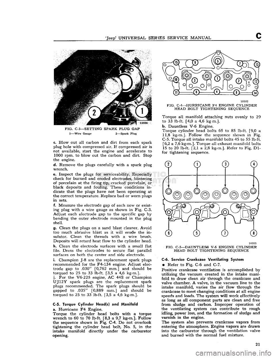
f. Measure the electrode gap of each new or exist
ing plug with a wire
gauge
as shown in Fig. C-3.
Adjust
each electrode gap to the specific gap by
bending the outer electrode mounted in the plug
shell.
g.
Clean
the plugs on a sand blast cleaner. Avoid
too much abrasive blast as it
will
erode the in
sulator.
Clean
the threads with a wire
brush.
Deposits
will
retard
heat flow to the cylinder head.
h.
Clean
the electrode surfaces with a small flat
file. Dress the electrodes to secure flat parallel surfaces on both the center and side electrode.
i.
Champion J-8 are the replacement
spark
plugs
recommended for the F4-134 engine. Adjust elec
trode gap to .030" [0,762 mm.] and should be
torqued to 25 to 33 lb-ft. [3,5 a 4,6 kg-m.].
j.
For the V6-225 engine, AC 44S or Champion
UJ12Y
spark
plugs are the replacement
spark
plugs recommended. The
spark
plugs should be gapped to .035" [0,889 mm.] and should be
torqued to 25 to 33 lb-ft. [3,5 a 4,6 kg-m.].
C-5. Torque Cylinder
Head(s)
and
Manifold
a.
Hurricane
F4 Engine.
Torque
the cylinder head bolts with a torque
wrench
to 60 to 70 lb-ft [8,3 a 9,7 kg-m.]. Follow
the sequence shown in Fig. C-4. Do not overlook
tightening the cylinder head bolt, No. 5, in the
intake
manifold directly under the carburetor
opening. 10102
FIG.
C-4—HURRICANE
F4
ENGINE CYLINDER HEAD BOLT TIGHTENING SEQUENCE
Torque
all manifold attaching nuts evenly to 29
to 33 lb-ft. [4,0 a 4,6 kg-m.].
b.
Dauntless V-6 Engine.
Torque
cylinder head bolts 65 to 85 lb-ft. [9,0 a 11,8 kg-m.]. Follow the sequence shown in Fig.
C-5.
Torque all intake manifold bolts 45 to 55 lb-ft. [6,2 a 7,6 kg-m.]. Torque all exhaust manifold bolts
15 to 20 lb-ft. [2,1 a 2,8 kg-m.]. Refer to Fig. Dl-
for tightening sequence. 14203
FIG.
C-5—DAUNTLESS
V-6
ENGINE CYLINDER HEAD BOLT TIGHTENING SEQUENCE C-6.
Service
Crankcase
Ventilating System
•
Refer to Fig. C-6 and C-7.
Positive crankcase ventilation is accomplished by
utilizing
the vacuum created in the intake mani
fold to draw clean air through the crankcase and
valve chamber. A valve, in the vacuum line to the
intake
manifold, varies the air flow through the
crankcase
to
meet
changing conditions at all engine
speeds
and loads. The system
will
work effectively as long as all component parts are clean and free
from
sludge and carbon. Improper operation of the ventilating system can contribute to rough
idling,
power loss, and the formation of sludge and
varnish
in the engine.
The
system also prevents crankcase vapors from
entering the atmosphere. Engine vapors are drawn
into the carburetor through the ventilation valve
and
burned with the normal fuel mixture. 21
Page 125 of 376
'Jeep'
UNIVERSAL
SERIES
SERVICE
MANUAL
E
is generally caused by excessive
engine
idle speed
in
combination with retarded ignition timing,
engine
heat soak or the use cf low octane fuel.
Should
engine
dieseling
(engine
running after ignition key is turned off) be experienced on V-6
engine
equipped vehicles, installation of Idle Stop
Valve
Kit
Part
No.
991722
will
correct the
difficulty.
E-43.
Fast
Idle Adjustment
No fast idle speed adjustment is required.
Fast
idle is controlled by the curb idle speed adjustment
screw.
If curb idle speed is correctly set and the choke rod is properly adjusted, fast idle speed
will
be correct;
E-44.
Dash Pot Adjustment —
F4
and V-6 Engine
•
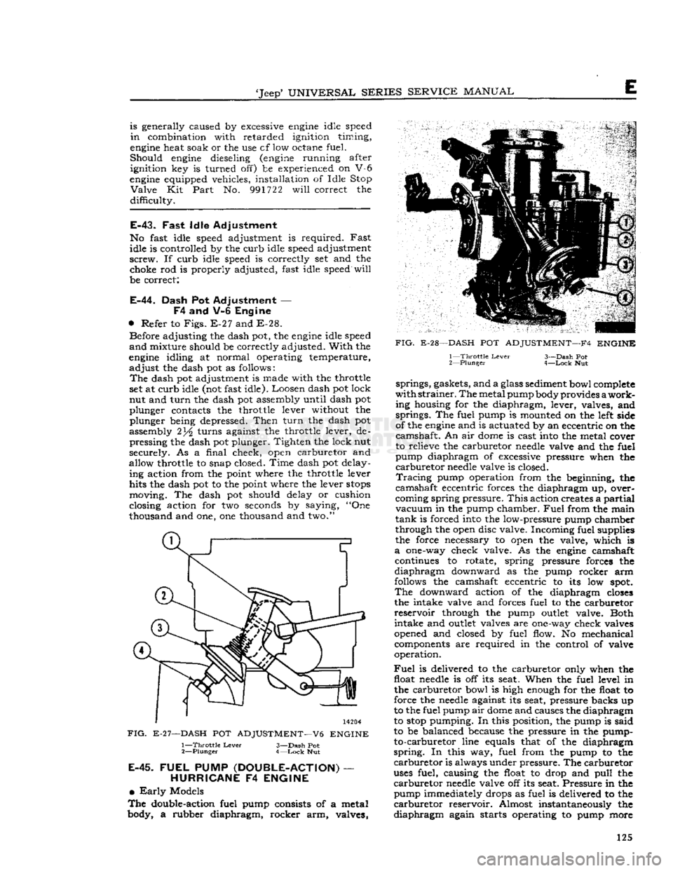
Refer to
Figs.
E-27 and E-28. Before adjusting the dash pot, the
engine
idle speed
and
mixture should be correctly adjusted.
With
the
engine
idling at normal operating temperature,
adjust
the dash pot as follows:
The
dash pot adjustment is made with the throttle
set at curb idle (not fast idle). Loosen dash pot lock
nut and
turn
the dash pot assembly until dash pot
plunger contacts the throttle lever without the plunger being depressed.
Then
turn
the dash pot
assembly 2turns against the throttle lever, de pressing the dash pot plunger. Tighten the lock nut
securely. As a final check, open carburetor and
allow throttle to snap closed. Time dash pot delay ing action from the point where the throttle lever
hits the dash pot to the point where the lever
stops
moving. The dash pot should delay or cushion
closing action for two seconds by saying, "One
thousand and one, one thousand and two."
14204
FIG.
E-27—DASH
POT
ADJUSTMENT—V6
ENGINE
1—
Throttle
Lever
3—Dash Pot
2—
Plunger
4—Lock
Nut
E-45.
FUEL
PUMP
(DOUBLE-ACTION)
—
HURRICANE
F4
ENGINE
•
Early
Models
The
double-action fuel pump consists of a metal
body, a rubber diaphragm, rocker arm, valves,
FIG.
E-28—DASH
POT
ADJUSTMENT—F4
ENGINE
1—
Throttle
Lever
3—Dash Pot
2—
Plunger
4—Lock
Nut springs, gaskets, and a glass sediment bowl complete
with
strainer.
The
metal pump body provides
a
work
ing housing for the diaphragm, lever, valves, and springs. The fuel pump is mounted on the left side
of the
engine
and is actuated by an eccentric on the
camshaft. An air
dome
is cast into the metal cover
to relieve the carburetor
needle
valve and the fuel
pump diaphragm of excessive pressure when the
carburetor
needle
valve is closed.
Tracing
pump operation from the beginning, the
camshaft eccentric forces the diaphragm up, over
coming spring pressure.
This
action creates a
partial
vacuum
in the pump chamber.
Fuel
from the main
tank
is forced into the low-pressure pump chamber
through the open disc valve. Incoming fuel supplies
the force necessary to open the valve, which is
a
one-way check valve. As the
engine
camshaft continues to rotate, spring pressure forces the
diaphragm
downward as the pump rocker arm
follows the camshaft eccentric to its low
spot.
The
downward action of the diaphragm
closes
the intake valve and forces fuel to the carburetor
reservoir
through the pump
outlet
valve. Both intake and
outlet
valves are one-way check valves
opened and closed by fuel flow. No mechanical components are required in the control of valve
operation.
Fuel
is delivered to the carburetor only when the float
needle
is off its seat. When the fuel level in the carburetor bowl is high enough for the float to
force the
needle
against its seat, pressure backs up
to the fuel pump air
dome
and causes the diaphragm
to
stop
pumping. In this position, the pump is said
to be balanced because the pressure in the pump- to-carburetor line equals that of the diaphragm
spring.
In this way, fuel from the pump to the
carburetor
is always under pressure. The carburetor
uses
fuel, causing the float to drop and
pull
the
carburetor
needle
valve off its seat. Pressure in the pump immediately drops as fuel is delivered to the
carburetor
reservoir. Almost instantaneously the
diaphragm
again starts operating to pump more 125
Page 126 of 376
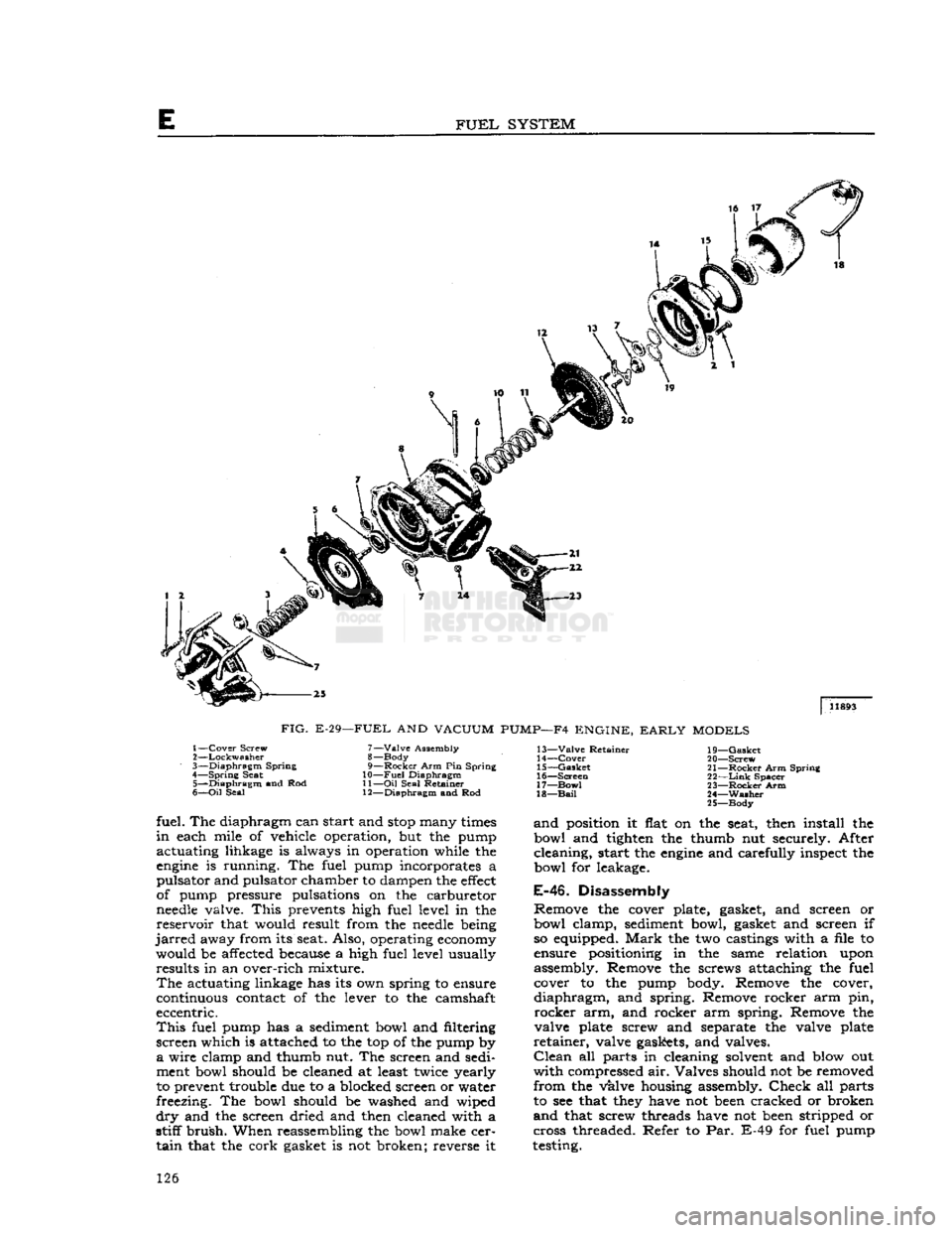
FUEL
SYSTEM
|
11893
FIG.
E-29—FUEL
AND
VACUUM
PUMP—F4
ENGINE,
EARLY
MODELS
1—
Cover
Screw
2—
Lockwasher
3—
Diaphragm
Spring
4—
Spring
Seat 5—
Diaphragm
and Rod
6—
Oil
Seal 7—
Valve
Assembly
8— Body
9—
Rocker
Arm Pin Spring
10—
Fuel
Diaphragm
11—
Oil
Seal Retainer
12—
Diaphragm
and Rod 13—
Valve
Retainer
14—
Cover
15—
Gasket
16—
Screen
17—
Bow!
18—
Bail
19—
Gasket
20—
Screw
21—
Rocker
Arm Spring
22—
Link
Spacer
23—
Rocker
Arm
24—
Washer
25—
Body
fuel. The diaphragm can start and
stop
many
times
in
each mile of vehicle operation, but the pump
actuating lihkage is always in operation while the
engine
is running. The fuel pump incorporates a
pulsator and pulsator chamber to dampen the
effect
of pump pressure pulsations on the carburetor
needle
valve.
This
prevents high fuel level in the
reservoir
that would result from the
needle
being
jarred
away from its seat. Also, operating
economy
would be affected because a high fuel level usually results in an over-rich mixture.
The
actuating linkage has its own spring to ensure
continuous contact of the lever to the camshaft
eccentric.
This
fuel pump has a sediment bowl and filtering
screen which is attached to the top of the pump by
a
wire clamp and thumb nut. The screen and sedi
ment bowl should be cleaned at least twice yearly
to prevent trouble due to a blocked screen or water
freezing. The bowl should be washed and wiped
dry
and the screen dried and then cleaned with a
stiff
brush.
When reassembling the bowl make cer
tain
that the cork gasket is not broken; reverse it
and
position it flat on the seat, then install the
bowl and tighten the thumb nut securely. After
cleaning, start the
engine
and carefully inspect the
bowl for leakage.
E-46.
Disassembly
Remove the cover plate, gasket, and screen or
bowl clamp, sediment bowl, gasket and screen if so equipped.
Mark
the two castings with a file to
ensure positioning in the same relation upon
assembly. Remove the screws attaching the fuel cover to the pump body. Remove the cover,
diaphragm,
and spring. Remove rocker arm pin,
rocker
arm, and rocker arm spring. Remove the
valve plate screw and separate the valve plate
retainer,
valve gaskets, and valves.
Clean
all parts in cleaning solvent and blow out
with
compressed air. Valves should not be removed
from
the valve housing assembly.
Check
all parts
to see that
they
have not
been
cracked or broken
and
that screw threads have not
been
stripped or
cross threaded. Refer to Par. E-49 for fuel pump
testing. 126
Page 130 of 376
E
FUEL
SYSTEM
taching screws and valve housing from the fuel
pump body.
c.
Remove the two screws in the valve housing
and
separate the filter cover and air
dome
dia
phragm.
d.
Remove the cam lever return spring, plug,
cam
lever pin, and cam lever from the pump body.
Tap
the cam lever pin out of body, using a drift
inserted through the small
hole
in the pump body.
e. Remove diaphragm from pump body.
f. Under normal service, the pump may be cleaned without further disassembly.
Note:
The oil seal (at top of spring in diaphragm
assembly) seals the spring side of the fuel
dia
phragm
from the crankcase. Any deposit, in
excess
of a few drops, of oil on the diaphragm indicates leakage past the oil seal. Be sure the seat for the
seal
in the pump body is clean and smooth.
E-63.
Fuel
Pump Cleaning and Inspection
Caution:
Do not immerse valves or diaphragm
in
cleaning solvent; wipe clean.
Clean
all metal parts of the fuel pump in solvent.
Brush
with a stiff-bristled
brush.
Dry with com
pressed
air.
Check
all parts to see that they are not
cracked
or broken and that the screw threads are
not damaged.
E-64.
Fuel
Pump Reassembly
•
Refer to Fig. E-32.
a.
Assemble the valve housing and filter cover, using a new air
dome
diaphragm. The opening
in
the air
dome
diaphragm is located over the
intake
valve. The filter cover is positioned cor
rectly
when the inlet passage in the cover aligns
with
the inlet valve. Tighten the attaching screws
alternately and securely.
b.
Lubricate
diaphragm assembly shaft, around
oil
seal, with
engine
oil. Position diaphragm as sembly on valve housing and thread all the attach ing screws through diaphragm.
(This
helps avoid
damage to the screw
holes
in diaphragm.)
c.
Place diaphragm assembly and valve housing
in
position on pump body (align marks made
before disassembly).
First
start all screws one
or
two threads; then tighten the screws alternately
and
securely.
d.
Lubricate
forked end of cam lever, pin bore
of body, and corresponding
hole
in lever, and the
pin
itself with
engine
oil.
Note:
Forked
end of lever
goes
around diaphragm
shaft. Be sure
loose
bumper washer on diaphragm shaft is on top of lever and
between
lever and fixed
washer
on shaft.
e.
Install
lever and pin. To install pin, use a drift
and
tap pin into the
hole
in the body until it hits
the
stop
on the
bottom
of the hole;
move
the lever while tapping, to align
hole
in lever with the pin;
then install plug.
Install
lever return spring.
f.
Install
a new filter bowl gasket in filter cover.
Place
bail
assembly in ears on cover and swing
to one side.
Install
spring and new filter element in
bowl and install bowl on pump. Position
bail
as
sembly under bowl; tighten retainer screw.
Caution:
Do not overtighten screw.
E-65.
Fuel
Pump Installation
a.
Make certain mating surfaces of fuel pump and
engine
cylinder case are clean. Cement a new gasket to mounting flange of fuel pump.
b.
Position fuel pump on cylinder block, so that
cam
lever of pump rests on fuel pump cam of cam
shaft. Secure pump to block with two cap screws
and
lock washers. Torque
bolts
13 to 17 lb-ft. [1,8
a
2,3 kg-m.].
c.
Connect intake and
outlet
fuel lines to fuel
pump.
E-66.
Fuel
Pump Testing
Whenever
the fuel pump is to be checked for pres
sure
or volume, follow the procedure outline in
Par.
C-23 of this manual.
Fuel
pump pressure is
important
for low pressure
will
seriously affect en
gine
operation and high pressure can cause exces
sive fuel consumption and flooding of the carbure
tor.
Should there be any doubt of normal opera
tion, check the procedure as outlined in Par. C-23.
In
addition to proper fuel pressure, volume of the
pump is also important. When testing for proper
pump pressure, be certain to also
test
for volume
as the pump may build up sufficient pressure, but
fail
to produce sufficient volume.
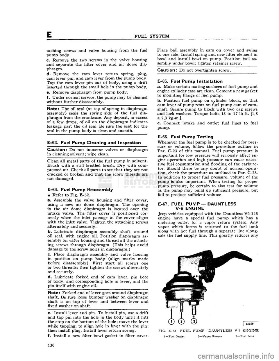
E-67. FUEL
PUMP
—
DAUNTLESS
V-6
ENGINE
Jeep vehicles equipped with the Dauntless V6-225
engine
have a special fuel pump which has a metering
outlet
for a vapor return system. Any
vapor
which forms is returned to the fuel tank
along with hot fuel through a separate line along
side the fuel supply line.
This
greatly reduces any
FIG.
E-33—FUEL PUMP—DAUNTLESS V-6 ENGINE
1
—Fuel
Outlet 2—Vapor
Return
3—Fuel
Inlet
130
Page 156 of 376
F2
EXHAUST EMISSION CONTROL SYSTEMS
the throttle
stop
screw to idle the
engine
at 650
to 700 rpm.
F2-17. Carburetor Idle Setting
The
"Lean
Best
Idle"
Method of Idle Setting is as
follows:
a.
Any scheduled service of ignition system should
precede this adjustment
b.
Connect tachometer to engine.
c.
Warm
up
engine
and stabilize temperatures.
d.
Adjust
engine
idle to speed desired, using throt
tle idle speed adjusting screw.
e.
Turn
idle mixture screws out (counterclockwise)
until
a
loss
of
engine
speed is indicated; then slowly
turn
mixture screws in (clockwise-leaner)
until
maximum speed (rpm) is reached. Continue
turning
in (clockwise) until speed begins to drop;
turn
mixture adjustment back out (counterclock
wise-richer)
until maximum speed is just regained
at
a "lean as possible" mixture adjustment.
F2-18. Distributor
The
ignition distributor used with the
Exhaust
Emission
Control
System is the same as that used
on
engines
without
Exhaust
Emission
Control.
Check
the distributor cam dwell angle and point
condition.
Check
ignition timing and adjust to specifications shown on the last
page
of this section.
F2-19.
Anti-Backfire
Valve
The
anti-backfire valve remains closed except when
the throttle is closed rapidly from an open position.
To
check the valve for proper operation, accelerate
the
engine
in neutral, allowing the throttle to close
rapidly.
The valve is operating satisfactorily when
no exhaust system backfire occurs. A further check
to determine whether the valve is functioning can
be made by removing from the anti-backfire valve
the large
hose
which connects the valve to the
pump.
With
a finger placed over the open end of
the
hose
(not the valve), accelerate the
engine
and allow the throttle to close rapidly. The valve is
operating satisfactorily if a momentary air rushing
noise is audible.
F2-20.
Check
Valve
The
check valves in the lines to the air distribution manifolds prevent the reverse flow of exhaust
gases
to the pump in the event the pump should, for
any
reason,
become
inoperative or should exhaust
pressure
ever exceed pump pressure.
To
check this valve for proper operation, remove the air supply
hose
from the pump at the check
valve.
With
the
engine
running, listen for exhaust
leakage at the check valve which is connected to
the distribution manifold.
F2-21.
Air
Pump
Check
for proper drive belt tension with belt tension
gauge
W-283. The belt strand tension should be 60 pounds measured on the
longest
accessible span
between two pulleys. DO NOT PRY ON THE
DIE
CAST
PUMP
HOUSING. To
check the pump for proper operation, remove
the air
outlet
hose
at the pump.
With
the
engine
running,
air discharge should be felt at one of
the pump
outlet
openings. The pump
outlet
air
pressure,
as determined by the relief valve, is preset
and
is not adjustable.
The
air pump
rear
cover assembly, housing the pressed in inlet and discharge tubes, and the pres
sure
relief valve are the only pump components
recommended for service replacement. These parts
are
to be replaced only when damaged as a result
of handling or in the event the relief valve was
tampered with.
F2-22.
Intake Manifold
Intake
manifold leaks must not be overlooked. Air
leakage at the intake manifold may be compen
sated for by
richer
idle mixture setting, however, this
will
usually cause uneven fuel-air distribution
and
will
always result in
loss
of performance and
exhaust emission control. To check for air leakage
into the intake manifold, apply kerosene or naph
tha,
on the intake manifold to cylinder head joints
and
observe whether any changes in
engine
rpm
occur.
If an air leak is indicated, check the mani
fold to cylinder head bolt torque. The correct torque is 25-35 lbs. ft. [3,46 a 4,84 kg-m.]. If the
leak
is
still
evident,
loosen
the manifold assembly
and
torque-tighten the bolts evenly.
Start
from the center and use proper torque values. Replace the
manifold
gasket if the leak
still
exists.
Clean
both
mating surfaces and check for
burrs
or other ir
regularities.
Always
torque the bolts evenly to the specified
torque value to prevent warpage.
F2-23.
Carburetor
Air
Cleaner
—Oil
Bath
Every
6,000
miles [9,600 km.] disconnect attach
ing
hoses
and unscrew the wing nut from the top
of the air cleaner and lift it off the carburetor.
Lift
the cover and filter element off the oil sump.
Clean
the inside surface of the sump and
refill
to
indicated
oil level with SAE 40 or 50
engine
oil
above 32 F; SAE 20 below 32 F.
Wash
filter element in kerosene and
drain.
Reassemble the air
cleaner
and install on carburetor.
More
frequent cleaning and replacement are advis able when the car is operated in dusty areas or on
unpaved
roads. Accumulated
dirt
restricts air flow,
reducing
fuel economy and performance.
F2-24.
REMOVAL PROCEDURES
The
following paragraphs
give
the procedures for removing the major units of the exhaust emission
control
system and the required equipment needed.
F2-2S.
Air
Pump
Loosen
the air pump mounting bracket bolts. Re move the air pump air hose(s). Separate the air pump from its mounting bracket. At time of install
ation,
torque tighten the air pump mounting bolts
to
30-40
lbs.-ft [4,15 a 5,53 kg-m.].
Adjust
the
belt strand tension to 60 pounds. 156
Page 172 of 376
H
ELECTRICAL
SYSTEM SUBJECT
PAR.
Directional
Signal
Lamps
H-138
Hazard
Warning
Lamps
H-139
Head
Lamp
Replacement H-130
Head
Lamp
Aiming Procedure H-131 Headlight Dimmer Switch H-127
License
Plate
Lamp
H-136
Main
Light
Switch. H-126
Marker
Lights .H-l40
Parking
and
Turn
Signal
Light
H-133
Stop
Light
Switch. H-l28
Tail,
Stop and
Turn
Signal
Lamp
.H-134
H-1. GENERAL
All
'Jeep' Universal vehicles are equipped with 12- volt electrical systems. Use caution around the higher
voltage
of the 12-volt system as accidental
short
circuits are more capable of damaging electri
cal
units. Also, arcs around the 12-volt battery are
more apt to ignite any gas that may be escaping
from
it. In the following paragraphs
will
be found
information about the battery, distributor, coil,
generator, alternator,
voltage
regulator and start ing motor. These units with the connecting wires,
make
up the
engine
electrical system. The wiring
diagram
will
show the different circuits of the en
gine
electrical system and the various units which
make
up
those
circuits.
With
plastic-covered wiring harnesses use only
rubber-insulated
wiring clips.
Caution:
All current production vehicles are 12- volt, negative ground. Whenever servicing a 12-
volt electrical system, use caution, as an accidental
short
circuit is capable of damaging electrical units. Disconnect battery ground cable before changing
electrical
components.
H-2.
Battery
The
battery is a storage reservoir for electrical
energy produced by the alternator or generator.
The
battery should store sufficient energy for
operation of the entire electrical system when the
alternator
or generator is not pr 1,scing output,
such
as when the ignition is first turned on. Of
particular
importance is maintaining the electrolyte
at the correct level, regularly checking with a
hydrometer, and maintaining clean, tight cable connections.
Battery
service information is given in this section.
Caution:
Do not allow flames or sparks to be
brought near the vent
openings
of the battery since
hydrogen gas may be present in the battery and might explode.
Note:
The liquid in the battery (electrolyte) is a
solution of sulphuric acid which, on contact, can
injure
skin or
eyes,
or damage clothes. If it is spilled
on the skin or spattered in the
eyes,
promptly flush
it
away with quantities of clear water only. If the
acid
is spilled on clothes, wet it thoroughly with a
weak
solution of ammonia, or with a solution of sodium bicarbonate or baking soda.
SUBJECT
PAR.
HORN
H-137
ELECTRICAL
COMPONENT
REPLACEMENT
H-150
WINDSHIPLD
WIPER SYSTEM
H-141
thru
149
SERVICE
DIAGNOSIS.
. .H-151
ELECTRICAL
SPECIFICATIONS
H-152
Caution:
When installing the battery, the nega
tive terminal must be grounded. Reverse polarity of the battery can cause severe damage to the charging system.
Battery
Inspection
a.
Check
the specific gravity of the electrolyte in
each cell of the battery. A hydrometer reading of 1.260 indicates that the battery is fully charged.
If
the reading is 1.225 or below, the battery
needs
recharging.
If one or more cells is 25 "points" (.025) or more lower than the other cells, this in
dicates that the cell is shorted, the cell is about to
fail,
or there is a
crack
in the battery partition in
the case. Unless the battery is repaired or replaced, battery trouble
will
soon
be experienced.
b.
Check
the electrolyte level in each cell, add
distilled
water to maintain the solution [9,5 mm.] above the plates. Avoid overfilling. Replace
the filler caps and tighten securely. It is important to keep the electrolyte level above the plates at all
times because plates that are
exposed
for any
length of time
will
be seriously damaged.
c.
Check
the wing nuts on the hold-down frame for tightness. Tighten them only with finger pres
sure,
never with pliers or a wrench. Excessive
pressure
could damage the battery case.
d.
Clean
the battery terminals and cable con nectors. Prepare a strong solution of baking soda
and
water and brush it around the terminals to
remove any corrosion that is present. The cell caps must be tight and their vents sealed to prevent
cleaning solution entering the cells. After cleaning,
connect cables to battery and coat the terminals
with
heavy grease.
e.
Inspect the battery cables and replace if badly
corroded
or frayed.
Check
tightness
of terminal
screws to ensure
good
electrical connections.
Check
the
tightness
of the negative ground cable connection at the frame to ensure a
good
ground
connection.
f.
Load
test
the battery. Connect a voltmeter across the battery. Run the starting motor for 15 seconds. If the
voltage
does
not drop below 10
volts the battery is satisfactory. If the
voltage
falls
below the figure given, yet the specific gravity is
above
1.225,
the condition of the battery is questionable.
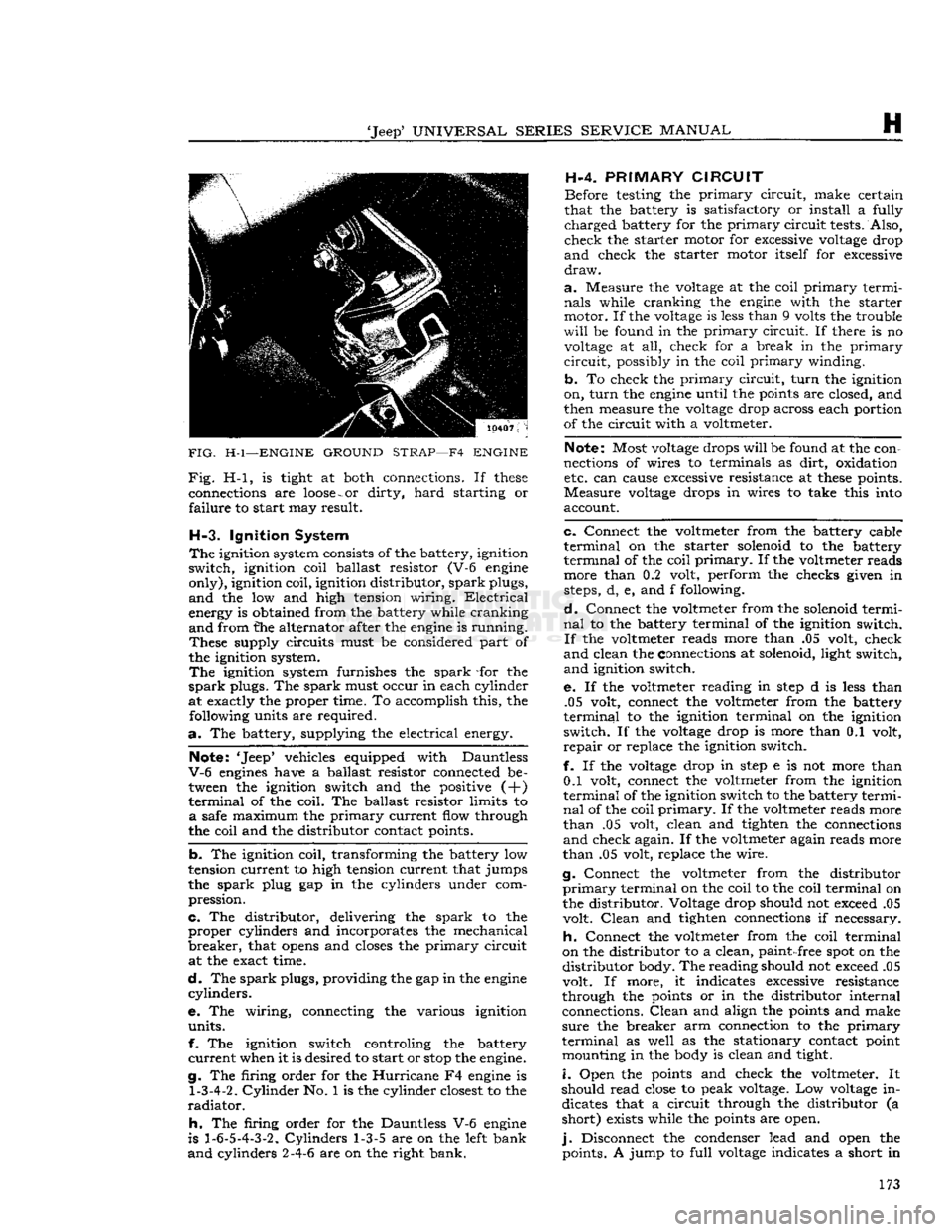
g. Be sure the
engine
ground strap connection, 172
Page 173 of 376
'Jeep'
UNIVERSAL
SERIES
SERVICE
MANUAL
H
FIG.
H-l—ENGINE
GROUND
STRAP—F4
ENGINE
Fig.
H-l, is tight at both connections. If
these
connections are
loose
-
or
dirty,
hard
starting or
failure
to start may result.
H-3.
Ignition System
The
ignition system consists of the battery, ignition
switch,
ignition coil ballast resistor (V-6 engine
only),
ignition coil, ignition distributor,
spark
plugs,
and
the low and high tension wiring.
Electrical
energy is obtained from the battery while cranking
and
from the alternator after the engine is running.
These
supply circuits must be considered part of
the ignition system.
The
ignition system furnishes the
spark
-for the
spark
plugs. The
spark
must occur in each cylinder
at exactly the proper time. To accomplish this, the following units are required.
a.
The battery, supplying the electrical energy.
Note: 'Jeep* vehicles equipped with Dauntless
V-6
engines have a ballast resistor connected be tween the ignition switch and the positive (+)
terminal
of the coil. The ballast resistor limits to
a
safe maximum the
primary
current flow through
the coil and the distributor contact points.
b.
The ignition coil, transforming the battery low
tension current to high tension current that jumps
the
spark
plug gap in the cylinders under com
pression.
c.
The distributor, delivering the
spark
to the
proper
cylinders and incorporates the mechanical
breaker,
that
opens
and closes the
primary
circuit at the exact time.
d.
The
spark
plugs, providing the gap in the engine
cylinders.
e. The wiring, connecting the various ignition
units.
f. The ignition switch controling the battery
current
when it is desired to start or
stop
the engine.
g. The firing order for the
Hurricane
F4 engine is
1-3-4-2.
Cylinder
No. 1 is the cylinder closest to the
radiator.
h.
The firing order for the Dauntless V-6 engine
is
1-6-5-4-3-2.
Cylinders
1-3-5 are on the left bank
and
cylinders 2-4-6 are on the right bank. H-4.
PRIMARY
CIRCUIT
Before testing the
primary
circuit,
make certain
that the battery is satisfactory or install a fully
charged
battery for the
primary
circuit
tests. Also,
check
the starter motor for excessive voltage drop
and
check the starter motor itself for excessive
draw.
a.
Measure the voltage at the coil
primary
termi
nals
while cranking the engine with the starter
motor. If the voltage is less than 9 volts the trouble
will
be found in the
primary
circuit.
If there is no voltage at all, check for a break in the
primary
circuit,
possibly in the coil
primary
winding.
b.
To check the
primary
circuit,
turn
the ignition
on,
turn
the engine until the points are closed, and
then measure the voltage drop across each portion
of the circuit with a voltmeter.
Note: Most voltage drops
will
be found at the con
nections of wires to terminals as
dirt,
oxidation etc. can cause excessive resistance at
these
points.
Measure
voltage drops in wires to take this into
account.
c.
Connect the voltmeter from the battery cable
terminal
on the starter solenoid to the battery
terminal
of the coil
primary.
If the voltmeter reads more than 0.2 volt, perform the checks given in
steps, d, e, and f following.
d.
Connect the voltmeter from the solenoid termi
nal
to the battery terminal of the ignition switch.
If
the voltmeter reads more than .05 volt, check
and
clean the connections at solenoid, light switch,
and
ignition switch.
e. If the voltmeter reading in
step
d is less than .05 volt, connect the voltmeter from the battery
terminal
to the ignition terminal on the ignition
switch.
If the voltage drop is more than 0.1 volt,
repair
or replace the ignition switch.
f. If the voltage drop in
step
e is not more than 0.1 volt, connect the voltmeter from the ignition
terminal
of the ignition switch to the battery termi
nal
of the coil
primary.
If the voltmeter reads more
than
.05 volt, clean and tighten the connections
and
check again. If the voltmeter again reads more
than
.05 volt, replace the wire.
g. Connect the voltmeter from the distributor
primary
terminal on the coil to the coil terminal on
the distributor. Voltage drop should not exceed .05 volt.
Clean
and tighten connections if necessary.
h.
Connect the voltmeter from the coil terminal
on the distributor to a clean,
paint-
free spot on the
distributor
body. The reading should not exceed .05
volt. If more, it indicates excessive resistance
through the points or in the distributor internal connections.
Clean
and align the points and make
sure
the breaker arm connection to the
primary
terminal
as well as the stationary contact point mounting in the body is clean and tight.
i.
Open the points and check the voltmeter. It
should read close to peak voltage. Low voltage in dicates that a circuit through the distributor (a
short)
exists while the points are open.
j.
Disconnect the condenser lead and open the points. A jump to
full
voltage indicates a short in 173
Page 175 of 376
'Jeep'
UNIVERSAL
SERIES
SERVICE
MANUAL
H
11514
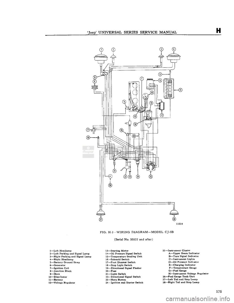
FIG.
H-2—WIRING
DIAGRAM—MODEL
CJ-3B
(Serial No.
35522
and
after)
1—
Left
Headlamp
2—
Left
Parking and Signal Lamp
3— Right Parking and Signal Lamp
4— Right Headlamp 5— Battery Ground Strap
6— Generator 7— Ignition
Coil
8— Junction Block
9—
Horn
10— Distributor
11— Battery
12—
Voltage
Regulator 13— Starting Motor
14—
Oil
Pressure Signal Switch 15— Temperature Sending Unit
16—
Solenoid
Switch 17— Foot Dimmer Switch
18—
Stop
Light Switch 19— Directional Signal Flasher
20— Fuse
21—
Light
Switch 22— Directional Signal Switch
23—
Horn
Button 24— Ignition and Starter Switch 25—Instrument Cluster
A—Upper Beam Indicator
B—Turn
Signal Indicator C—Instrument Lights
D—Oil
Pressure Indicator
E—Charging
Indicator F—Temperature Gauge
G—Fuel
Gauge
H—Instrument
Voltage
Regulator
25—Fuel Gauge Tank Unit
27—
Left
Tail
and
Stop
Lamp
28— Right
Tail
and
Stop
Lamp 175