tow JEEP COMMANDER 2010 1.G Owner's Manual
[x] Cancel search | Manufacturer: JEEP, Model Year: 2010, Model line: COMMANDER, Model: JEEP COMMANDER 2010 1.GPages: 78, PDF Size: 7.31 MB
Page 46 of 78
24 HOUR TOWING ASSISTANCE
• Dial toll-free 1-800-521-2779.
• Provide your name, vehicle identification number and license plate number.
• Provide your location, including telephone number, from which you are calling.
• Briefly describe the nature of the problem and answer a few simple questions.
• You will be given the name of the service provider and an estimated time of arrival. If youfeel you are in an “unsafe situation”, please let us know. With your consent, we will
contact local police or safety authorities.
INSTRUMENT CLUSTER WARNING LIGHTS
- Electronic Stability Program (ESP) Indicator Light
• If this indicator light flashes during acceleration, apply as little throttle as possible. Whiledriving, ease up on the accelerator. Adapt your speed and driving to the prevailing road
conditions. To improve the vehicles traction when starting off in deep snow, sand or
gravel, it may be desirable to switch the ESP system off.
- Tire Pressure Monitoring System (TPMS) Light
• A Tire Pressure Monitoring Light and a “low tire” message will display in your instrumentcluster along with an audible chime if one or more of your vehicle’s four road tires are
significantly under-inflated.
• Check the inflation pressure of each tire and inflate to the recommended pressure for your vehicle. The tire pressures recommended for your vehicle are found on the “Tire and
Loading Information” label located on the driver’s side door opening. The TPMS light
should not be used as a tire pressure gauge when adjusting your tire pressure.
• It is recommended that you check the tire pressure in the morning when tires are cool; inflate each tire to the recommended pressure for your vehicle. The light will turn off
after your vehicle’s tire pressures are properly inflated and the pressure has been
recognized. The vehicle may need to be driven for up to 20 minutes above 15 mph
(25 km/h) before the light will turn off.
• Temperature changes can affect tire pressure, causing the TPMS light to turn on. Tire pressures will also increase as the vehicle is driven – this is normal and you should not
adjust for this increased pressure.
• Driving on under-inflated tires reduces your vehicle’s fuel efficiency and tire tread life. If a spare tire is in use on the vehicle, the TPMS light may turn on.
- Brake Warning Light
• The Brake Warning light illuminates when there is either a system malfunction or theparking brake is applied. If the light is on and the parking brake is not applied, it
indicates a possible brake hydraulic malfunction, brake booster problem or an Anti-Lock
Brake System problem.
• We recommend you drive to the nearest Service Center and have the vehicle serviced immediately.
WHAT TO DO IN EMERGENCIES
44
Page 47 of 78
WARNING!
Driving a vehicle with the red brake light on is dangerous. Part of the brake system
may have failed. It will take longer to stop the vehicle. You could have an accident.
Have the vehicle checked immediately.
- Malfunction Indicator Light (MIL)
• Certain conditions, such as a loose or missing gas cap, poor fuel quality, etc., mayilluminate the MIL after engine start. The vehicle should be serviced if the light stays on
through several typical driving cycles. In most situations, the vehicle will drive normally
and not require towing.
• If the MIL flashes when the engine is running, serious conditions may exist that could lead to immediate loss of power or severe catalytic converter damage. We recommend
you do not operate the vehicle. Have the vehicle serviced as soon as possible if this
occurs.
- Electronic Stability Program (ESP) Indicator Light/Brake Assist
System (BAS) Warning Light
• If the ESP/BAS warning light comes on continuously with the engine running, a malfunction has been detected.
• If this light remains on after several ignition cycles, and the vehicle has been driven several miles (kilometers) at speeds greater than 30 mph (48 km/h), we recommend you
drive to the nearest Service Center as soon as possible to have the problem diagnosed
and corrected.
- Charging System Light
• This light shows the status of the electrical charging system. If the charging system lightremains on, it means that the vehicle is experiencing a problem with the charging
system.
• We recommend you do not continue driving if the charging system light is on. Have the vehicle serviced immediately.
- Oil Pressure Warning Light
• This light indicates low engine oil pressure. If the light turns on while driving, stop thevehicle and shut off the engine as soon as possible. A chime will sound for four minutes
when this light turns on.
• We recommend you do not operate the vehicle or engine damage will occur. Have the vehicle serviced immediately.
- Anti-Lock Brake (ABS) Light
• This light monitors the Anti-Lock Brake System (ABS).
• If the light is not on during starting, stays on, or turns on while driving, we recommendyou drive to the nearest Service Center and have the system serviced as soon as
possible.
45
WHAT TO DO IN EMERGENCIES
Page 48 of 78
- Electronic Throttle Control (ETC) Light
• This light informs you of a problem with the Electronic Throttle Control (ETC) system.
• If a problem is detected, the light will come on while the engine is running. Cycle theignition key when the vehicle has completely stopped and the shift lever is placed in the
PARK position; the light should turn off.
• If the light remains lit with the engine running, your vehicle will usually be drivable; however, see an authorized dealer for service as soon as possible. If the light is flashing
when the engine is running, immediate service is required and you may experience
reduced performance, an elevated/rough idle or engine stall and your vehicle may
require towing.
- Airbag Warning Light
• If the light is not on during starting, stays on, or turns on while driving, we recommendyou drive to the nearest Service Center and have the system serviced as soon as
possible.
Fuel Cap/Loose Gas Cap Message
• If a “gas cap” message (shown as Check Gascap) appears, tighten the gas cap until a“clicking” sound is heard.
• If the message continues to appear for more than three days after tightening the gas cap, see your dealer.
Oil Change Indicator
Message
• If an “oil change” message (shown as Oil Change Required) appears and a single chimesounds, it is time for your next required oil change.
Resetting The Light After Servicing
• Turn the ignition switch to the ON/RUN position (do not start engine).
• Fully depress the accelerator pedal three times within 10 seconds.
• Turn the ignition switch to the OFF/LOCK position.
WHAT TO DO IN EMERGENCIES
46
Page 51 of 78
Spare Tire Stowage
• To remove or stow the spare, use the jack handle to rotate the “spare tire drive” nut whichis located under a plastic cover under the cargo load floor, just inside the liftgate opening.
• Lower the spare tire by turning the drive nut counterclockwise with the jack-handle assembly until the spare tire is on the ground with enough cable slack to allow you to
pull the spare tire out from underneath the vehicle.
• When the spare is clear, tilt the retainer at the end of the cable and pull it through the center of the wheel.
Preparations For Jacking
• Park on a firm, level surface. Avoid ice or slippery areas.
• Set the parking brake and shift the automatic transmission into PARK.
• Turn the ignition to LOCK and turn on the Hazard Warning flasher.
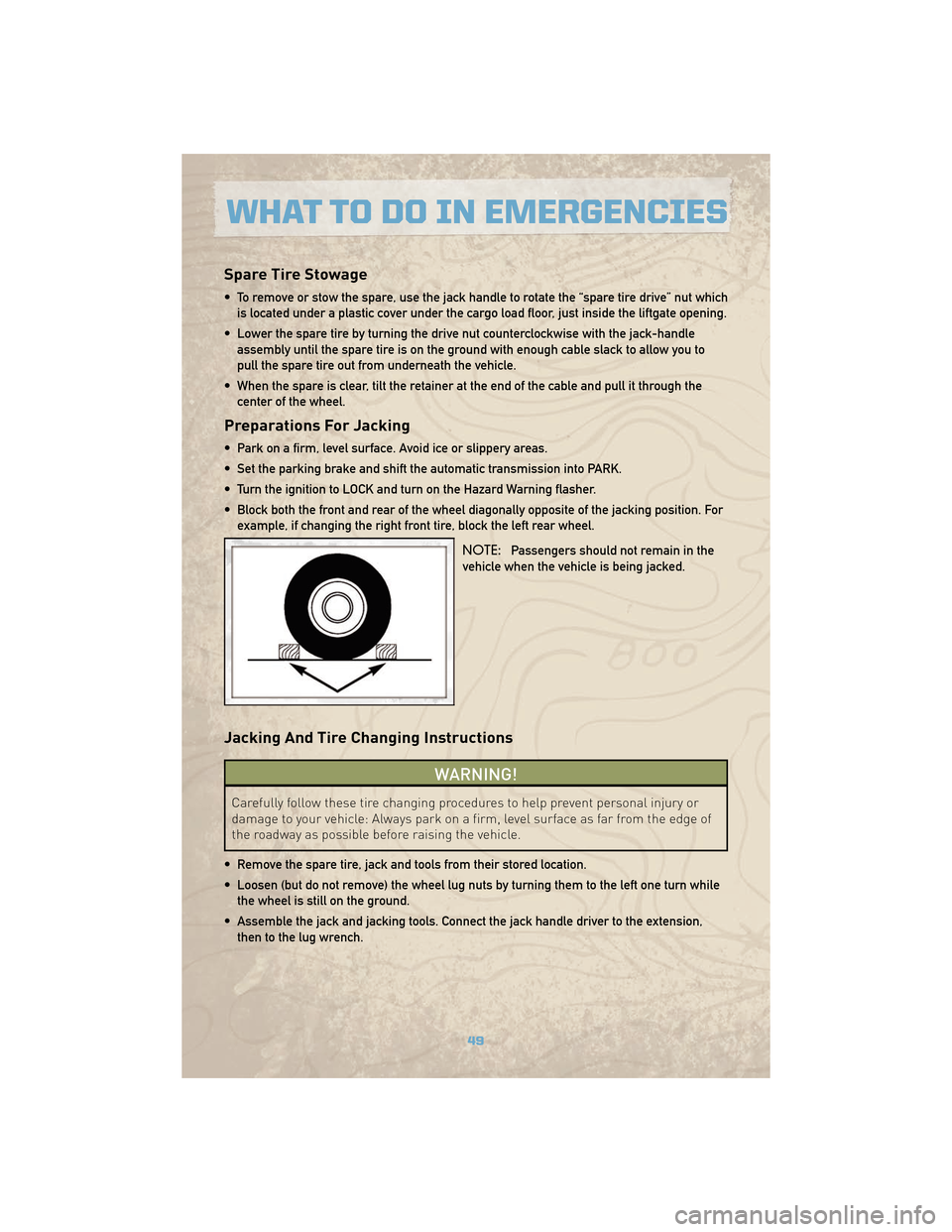
• Block both the front and rear of the wheel diagonally opposite of the jacking position. Forexample, if changing the right front tire, block the left rear wheel.
NOTE:Passengers should not remain in the
vehicle when the vehicle is being jacked.
Jacking And Tire Changing Instructions
WARNING!
Carefully follow these tire changing procedures to help prevent personal injury or
damage to your vehicle: Always park on a firm, level surface as far from the edge of
the roadway as possible before raising the vehicle.
• Remove the spare tire, jack and tools from their stored location.
• Loosen (but do not remove) the wheel lug nuts by turning them to the left one turn while the wheel is still on the ground.
• Assemble the jack and jacking tools. Connect the jack handle driver to the extension, then to the lug wrench.
49
WHAT TO DO IN EMERGENCIES
Page 52 of 78
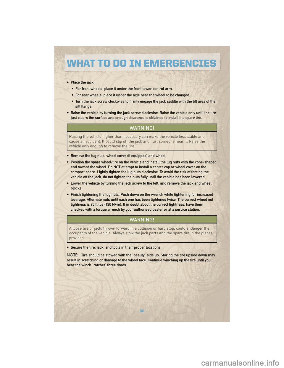
• Place the jack:• For front wheels, place it under the front lower control arm.
• For rear wheels, place it under the axle near the wheel to be changed.
• Turn the jack screw clockwise to firmly engage the jack saddle with the lift area of thesill flange.
• Raise the vehicle by turning the jack screw clockwise. Raise the vehicle only until the tire just clears the surface and enough clearance is obtained to install the spare tire.
WARNING!
Raising the vehicle higher than necessary can make the vehicle less stable and
cause an accident. It could slip off the jack and hurt someone near it. Raise the
vehicle only enough to remove the tire.
• Remove the lug nuts, wheel cover (if equipped) and wheel.
• Position the spare wheel/tire on the vehicle and install the lug nuts with the cone-shaped end toward the wheel. Do NOT attempt to install a center cap or wheel cover on the
compact spare. Lightly tighten the lug nuts clockwise. To avoid the risk of forcing the
vehicle off the jack, do not tighten the nuts fully until the vehicle has been lowered.
• Lower the vehicle by turning the jack screw to the left, and remove the jack and wheel blocks.
• Finish tightening the lug nuts. Push down on the wrench while tightening for increased leverage. Alternate nuts until each one has been tightened twice. The correct wheel nut
tightness is 95 ft lbs (130 N•m). If in doubt about the correct tightness, have them
checked with a torque wrench by your authorized dealer or at a service station.
WARNING!
A loose tire or jack, thrown forward in a collision or hard stop, could endanger the
occupants of the vehicle. Always stow the jack parts and the spare tire in the places
provided.
• Secure the tire, jack, and tools in their proper locations.
NOTE: Tire should be stowed with the “beauty” side up. Storing the tire upside down may
result in scratching or damage to the wheel face. Continue winching up the tire until you
hear the winch “ratchet” three times.
WHAT TO DO IN EMERGENCIES
50
Page 55 of 78
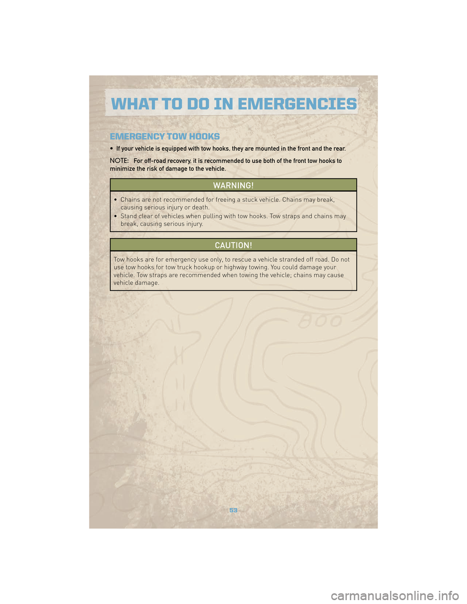
EMERGENCY TOW HOOKS
• If your vehicle is equipped with tow hooks, they are mounted in the front and the rear.
NOTE:For off-road recovery, it is recommended to use both of the front tow hooks to
minimize the risk of damage to the vehicle.
WARNING!
• Chains are not recommended for freeing a stuck vehicle. Chains may break, causing serious injury or death.
• Stand clear of vehicles when pulling with tow hooks. Tow straps and chains may break, causing serious injury.
CAUTION!
Tow hooks are for emergency use only, to rescue a vehicle stranded off road. Do not
use tow hooks for tow truck hookup or highway towing. You could damage your
vehicle. Tow straps are recommended when towing the vehicle; chains may cause
vehicle damage.
53
WHAT TO DO IN EMERGENCIES
Page 56 of 78
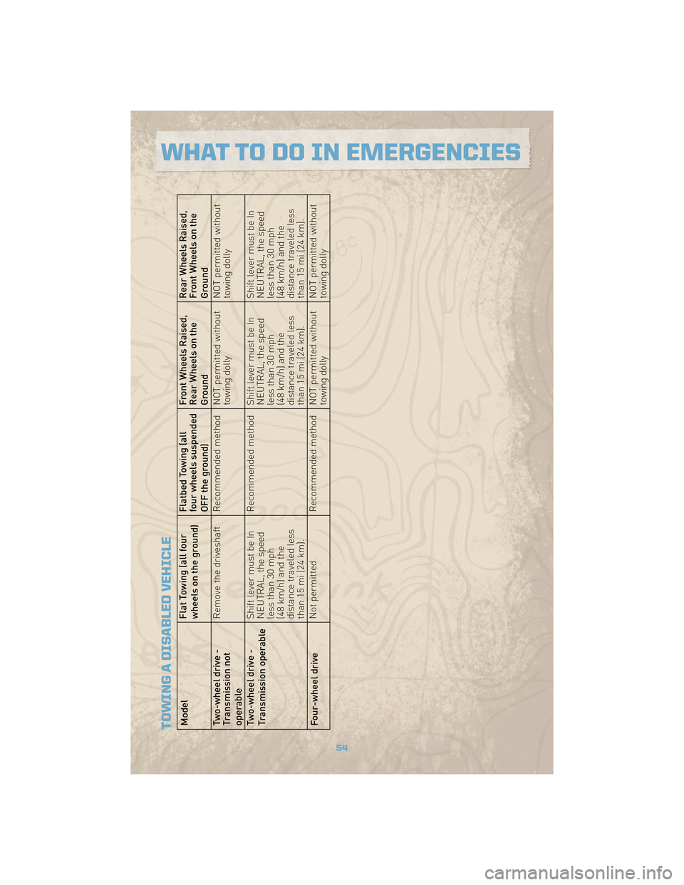
TOWING A DISABLED VEHICLEModelFlat Towing (all four
wheels on the ground)Flatbed Towing (all
four wheels suspended
OFF the ground)Front Wheels Raised,
Rear Wheels on the
GroundRear Wheels Raised,
Front Wheels on the
Ground
Two-wheel drive -
Transmission not
operable Remove the driveshaft Recommended method NOT permitted without
towing dollyNOT permitted without
towing dolly
Two-wheel drive -
Transmission operable Shift lever must be In
NEUTRAL, the speed
less than 30 mph
(48 km/h) and the
distance traveled less
than 15 mi (24 km).Recommended method Shift lever must be In
NEUTRAL, the speed
less than 30 mph
(48 km/h) and the
distance traveled less
than 15 mi (24 km).Shift lever must be In
NEUTRAL, the speed
less than 30 mph
(48 km/h) and the
distance traveled less
than 15 mi (24 km).
Four-wheel drive Not permitted
Recommended method NOT permitted without
towing dollyNOT permitted without
towing dolly
54
WHAT TO DO IN EMERGENCIES
Page 62 of 78
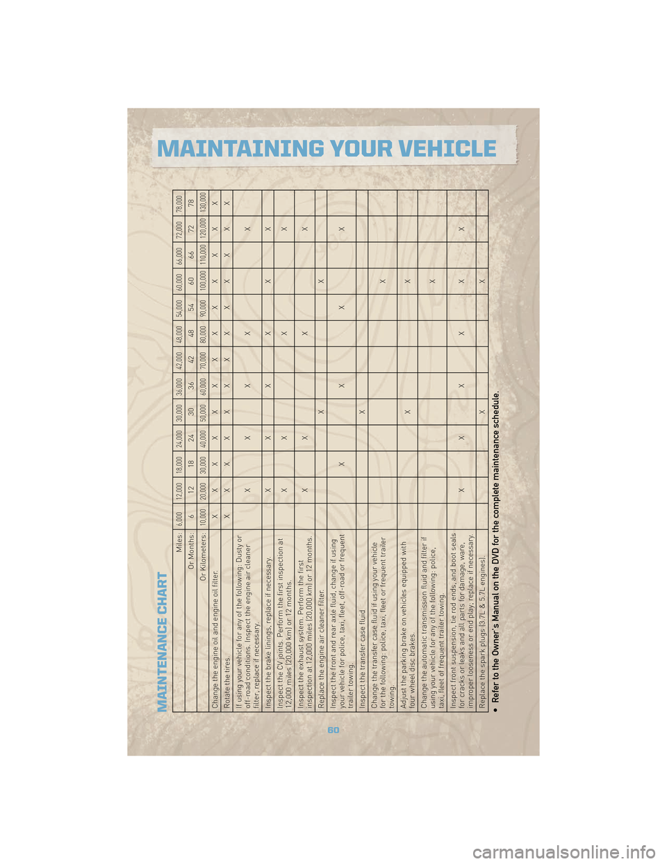
MAINTENANCE CHART
Miles:
6,000 12,000 18,000 24,000 30,000 36,000 42,000 48,000 54,000 60,000 66,000 72,000 78,000
Or Months: 6 12 18 24 30 36 42 48 54 60 66 72 78
Or Kilometers:
10,000 20,000 30,000 40,000 50,000 60,000 70,000 80,000 90,000 100,000 110,000 120,000 130,000
Change the engine oil and engine oil filter. XXXXXXXXXXXXX
Rotatethetires. XXXXXXXXXXXXX
If using your vehicle for any of the following: Dusty or
off-road conditions. Inspect the engine air cleaner
filter, replace if necessary. XXXX
X
Inspect the brake linings, replace if necessary. XXXXXX
Inspect the CV joints. Perform the first inspection at
12,000 miles (20,000 km) or 12 months. X
XXX
Inspect the exhaust system. Perform the first
inspection at 12,000 miles (20,000 km) or 12 months. X
XXX
Replace the engine air cleaner filter. XX
Inspect the front and rear axle fluid, change if using
your vehicle for police, taxi, fleet, off-road or frequent
trailer towing. XXXX
Inspect the transfer case fluid X
Change the transfer case fluid if using your vehicle
for the following: police, taxi, fleet or frequent trailer
towing. X
Adjust the parking brake on vehicles equipped with
four wheel disc brakes. XX
Change the automatic transmission fluid and filter if
using your vehicle for any of the following: police,
taxi, fleet of frequent trailer towing. X
Inspect front suspension, tie rod ends, and boot seals
for cracks or leaks and all parts for damage, ware,
improper looseness or end play; replace if necessary. XXXXXX
Replace the spark plugs (3.7L & 5.7L engines). XX• Refer to the Owner's Manual on the DVD for the complete maintenance schedule.
60
MAINTAINING YOUR VEHICLE
Page 65 of 78
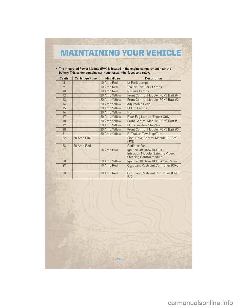
• The Integrated Power Module (IPM) is located in the engine compartment near thebattery. This center contains cartridge fuses, mini-fuses and relays.
Cavity Cartridge Fuse Mini-Fuse Description
8 10 Amp Red Lt Park Lamps
9 10 Amp Red Trailer-Tow Park Lamps
10 10 Amp Red Rt Park Lamps
12 20 Amp Yellow Front Control Module (FCM) Batt #4
13 20 Amp Yellow Front Control Module (FCM) Batt #2
14 20 Amp Yellow Adjustable Pedal
15 20 Amp Yellow Ft Fog Lamps
16 20 Amp Yellow Horn
17 20 Amp Yellow Rear Fog Lamps (Export Only)
18 20 Amp Yellow Front Control Module (FCM) Batt #1
19 20 Amp Yellow Lt Trailer-Tow Stop/Turn
20 20 Amp Yellow Front Control Module (FCM) Batt #3
21 20 Amp Yellow Rt Trailer-Tow Stop/Turn
22 30 Amp Pink Final Drive Control Module (FDCM)
MOD
23 50 Amp Red Radiator Fan
27 15 Amp Blue Ignition Off Draw (IOD) #1 —
Intrusion Module, Satellite Video,
Steering Control Module
28 20 Amp Yellow Ignition Off Draw (IOD) #2 — Radio
29 10 Amp Red Occupant Restraint Controller (ORC)
R/S
30 10 Amp Red Occupant Restraint Controller (ORC)
R/O
63
MAINTAINING YOUR VEHICLE
Page 66 of 78
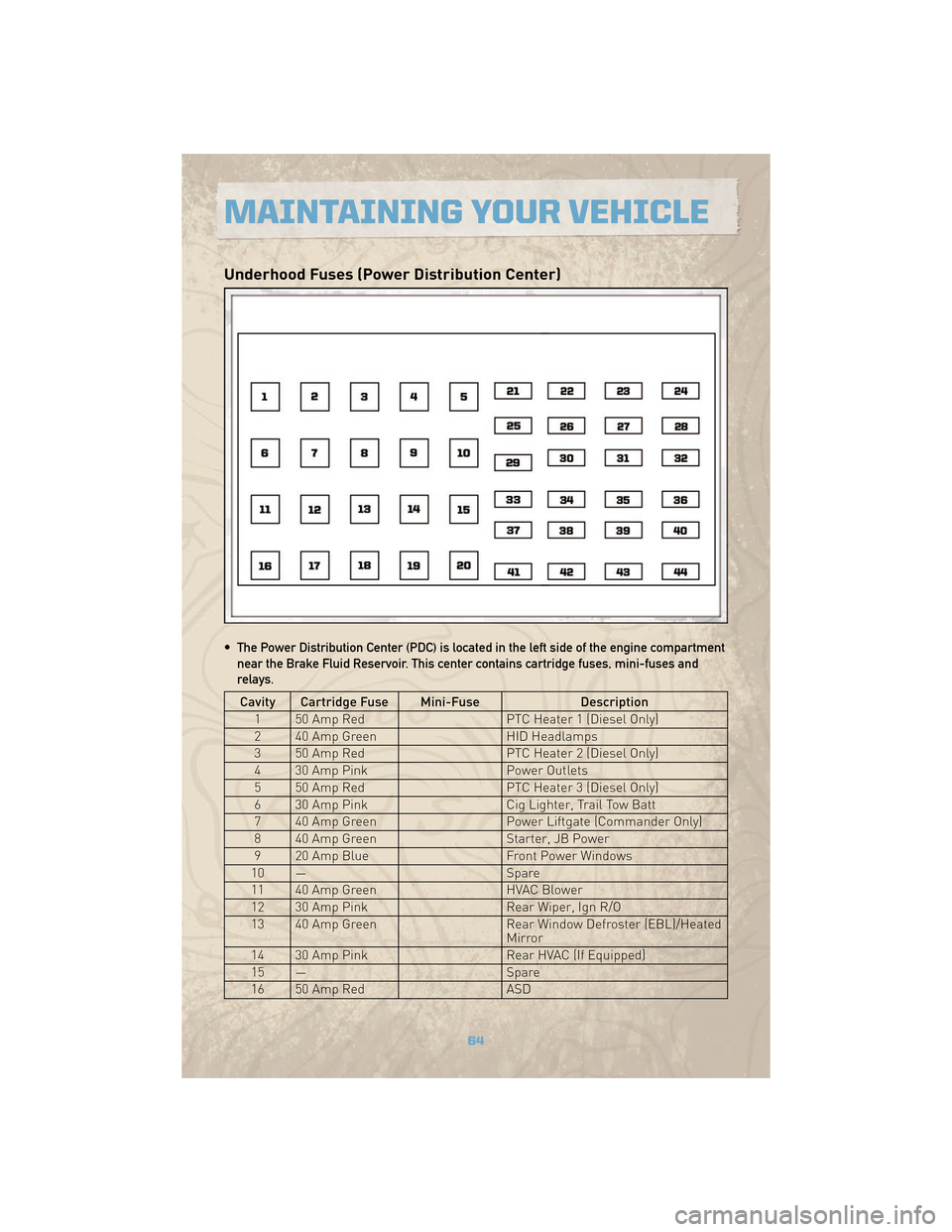
Underhood Fuses (Power Distribution Center)
• The Power Distribution Center (PDC) is located in the left side of the engine compartmentnear the Brake Fluid Reservoir. This center contains cartridge fuses, mini-fuses and
relays.
Cavity Cartridge Fuse Mini-Fuse Description
1 50 Amp Red PTC Heater 1 (Diesel Only)
2 40 Amp Green HID Headlamps
3 50 Amp Red PTC Heater 2 (Diesel Only)
4 30 Amp Pink Power Outlets
5 50 Amp Red PTC Heater 3 (Diesel Only)
6 30 Amp Pink Cig Lighter, Trail Tow Batt
7 40 Amp Green Power Liftgate (Commander Only)
8 40 Amp Green Starter, JB Power
9 20 Amp Blue Front Power Windows
10 — Spare
11 40 Amp Green HVAC Blower
12 30 Amp Pink Rear Wiper, Ign R/O
13 40 Amp Green Rear Window Defroster (EBL)/Heated
Mirror
14 30 Amp Pink Rear HVAC (If Equipped)
15 — Spare
16 50 Amp Red ASD
MAINTAINING YOUR VEHICLE
64