ad blue JEEP COMMANDER 2010 1.G User Guide
[x] Cancel search | Manufacturer: JEEP, Model Year: 2010, Model line: COMMANDER, Model: JEEP COMMANDER 2010 1.GPages: 78, PDF Size: 7.31 MB
Page 37 of 78
WARNING!
To Avoid Serious Injury or Death: Do not use a three-prong adaptor. Do not insert any
objects into the receptacles. Do not touch with wet hands. Close the lid when not in
use. If this outlet is mishandled, it may cause an electric shock and failure.
POWER OUTLET
• The two front power outlets are located on the instrument panel below the ClimateControls. The right side outlet is powered only when the key is in the ON position. The left
side outlet is powered directly from the battery and will receive power whether the
ignition is in the ON or LOCK position. All accessories connected to the left outlet should
be removed or turned off when the vehicle is not in use to protect the battery against
discharge.
• The rear power outlet is located in the left rear cargo area and will receive power whether the ignition is in the ON or LOCK position. All accessories connected to the rear
outlet should be removed or turned off when the vehicle is not in use to protect the
battery against discharge.
NOTE: Do not exceed the maximum power of 160 Watts (13 Amps) at 12 Volts. If the 160
Watt (13 Amp) power rating is exceeded the fuse protecting the system will need to be
replaced.
uconnect™ phone
• The uconnect™ phone is a voice-activated, hands-free, in-vehicle communications system.
• The uconnect™ phone allows you to dial a phone number with your cellular phone using simple voice commands.
• Please refer to uconnect™ phone in the uconnect™ User's Manual on the DVD for further details.
WARNING!
• Any voice commanded system should be used only in safe driving conditions following local laws and phone use. All attention should be kept on the roadway
ahead. Failure to do so may result in an accident causing serious injury or death.
• Your phone must be turned on and paired to the uconnect™ phone to allow use of this vehicle feature in emergency situations, when the cellular phone has network
coverage and stays paired to the uconnect™ phone.
NOTE: The uconnect™ phone requires a cellular phone equipped with the Bluetooth
®
Hands-Free Profile, Version 0.96 or higher. For uconnect™ customer support, call
1–877–855–8400.
35
ELECTRONICS
Page 38 of 78
Phone Pairing
NOTE:Pairing is a one-time initial setup before using the phone. You will also need to
follow the Bluetooth instructions in your cell phone user guide to complete the phone
pairing setup.
• Press the Phone button
to begin.
• Wait for the “ready” prompt and beep.
• (After the BEEP), say “uconnect setup”.
• (After the BEEP), say “phone pairing”.
• (After the BEEP) say, “pair a phone”.
• Follow the audible prompts.
• You will be asked to create a four-digit PIN which you will later need to enter into your phone (typically..settings, bluetooth, device, list, new).
• You will then be prompted to give the phone pairing a name (each phone paired should have a unique name).
• Next you will be asked to give this new pairing a priority of 1 thru 7 (up to seven phones may be paired).
Making A Phone Call
• Press the Phone button.
• (After the BEEP), say “dial” (or “call” to a name).
• (After the BEEP), say number (or name).
Phonebook (uconnect™ local) Edit
• Press the Phone button.
• (After the BEEP), say “phonebook”.
• (After the BEEP), say “new entry” or “list names” or “delete”.
• Follow the prompts.
Receiving A Call – Accept (And End)
• When an incoming call rings / is announced on uconnect™, press the Phone button.
• To end a call, press the Phone button
.
Mute (Or Unmute) Microphone During Call
• During a call, press the Voice button.
• (After the BEEP), say “mute on” (or “mute off ”).
Transfer Ongoing Call Between Handset And Vehicle
• During a call, press the Voice button.
• (After the BEEP), say “transfer call”.
ELECTRONICS
36
Page 65 of 78
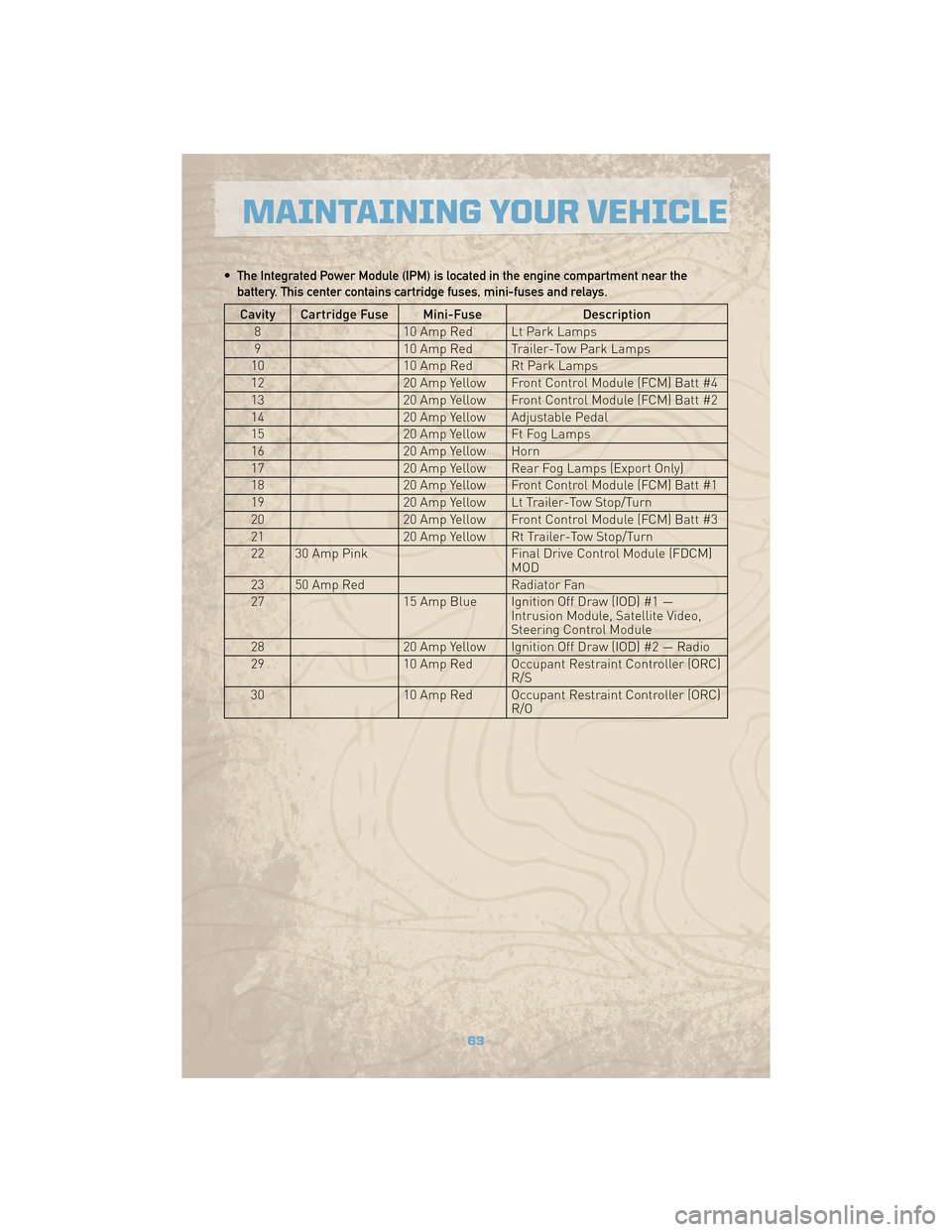
• The Integrated Power Module (IPM) is located in the engine compartment near thebattery. This center contains cartridge fuses, mini-fuses and relays.
Cavity Cartridge Fuse Mini-Fuse Description
8 10 Amp Red Lt Park Lamps
9 10 Amp Red Trailer-Tow Park Lamps
10 10 Amp Red Rt Park Lamps
12 20 Amp Yellow Front Control Module (FCM) Batt #4
13 20 Amp Yellow Front Control Module (FCM) Batt #2
14 20 Amp Yellow Adjustable Pedal
15 20 Amp Yellow Ft Fog Lamps
16 20 Amp Yellow Horn
17 20 Amp Yellow Rear Fog Lamps (Export Only)
18 20 Amp Yellow Front Control Module (FCM) Batt #1
19 20 Amp Yellow Lt Trailer-Tow Stop/Turn
20 20 Amp Yellow Front Control Module (FCM) Batt #3
21 20 Amp Yellow Rt Trailer-Tow Stop/Turn
22 30 Amp Pink Final Drive Control Module (FDCM)
MOD
23 50 Amp Red Radiator Fan
27 15 Amp Blue Ignition Off Draw (IOD) #1 —
Intrusion Module, Satellite Video,
Steering Control Module
28 20 Amp Yellow Ignition Off Draw (IOD) #2 — Radio
29 10 Amp Red Occupant Restraint Controller (ORC)
R/S
30 10 Amp Red Occupant Restraint Controller (ORC)
R/O
63
MAINTAINING YOUR VEHICLE
Page 66 of 78
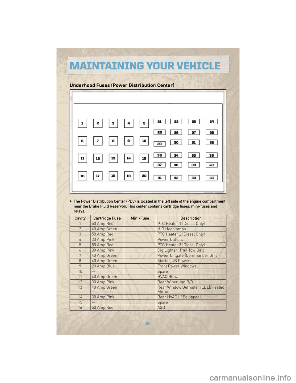
Underhood Fuses (Power Distribution Center)
• The Power Distribution Center (PDC) is located in the left side of the engine compartmentnear the Brake Fluid Reservoir. This center contains cartridge fuses, mini-fuses and
relays.
Cavity Cartridge Fuse Mini-Fuse Description
1 50 Amp Red PTC Heater 1 (Diesel Only)
2 40 Amp Green HID Headlamps
3 50 Amp Red PTC Heater 2 (Diesel Only)
4 30 Amp Pink Power Outlets
5 50 Amp Red PTC Heater 3 (Diesel Only)
6 30 Amp Pink Cig Lighter, Trail Tow Batt
7 40 Amp Green Power Liftgate (Commander Only)
8 40 Amp Green Starter, JB Power
9 20 Amp Blue Front Power Windows
10 — Spare
11 40 Amp Green HVAC Blower
12 30 Amp Pink Rear Wiper, Ign R/O
13 40 Amp Green Rear Window Defroster (EBL)/Heated
Mirror
14 30 Amp Pink Rear HVAC (If Equipped)
15 — Spare
16 50 Amp Red ASD
MAINTAINING YOUR VEHICLE
64
Page 67 of 78
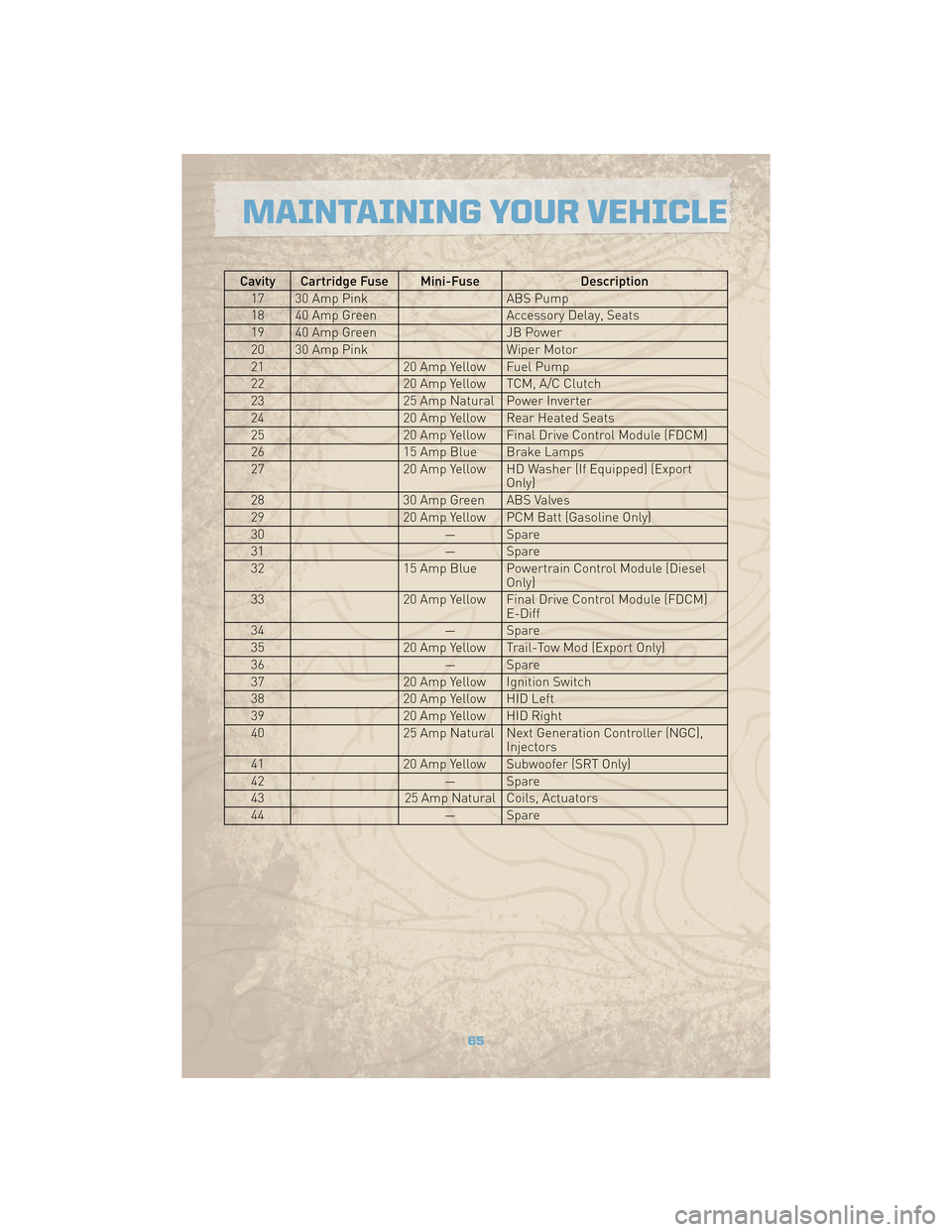
Cavity Cartridge Fuse Mini-FuseDescription
17 30 Amp Pink ABS Pump
18 40 Amp Green Accessory Delay, Seats
19 40 Amp Green JB Power
20 30 Amp Pink Wiper Motor
21 20 Amp Yellow Fuel Pump
22 20 Amp Yellow TCM, A/C Clutch
23 25 Amp Natural Power Inverter
24 20 Amp Yellow Rear Heated Seats
25 20 Amp Yellow Final Drive Control Module (FDCM)
26 15 Amp Blue Brake Lamps
27 20 Amp Yellow HD Washer (If Equipped) (Export
Only)
28 30 Amp Green ABS Valves
29 20 Amp Yellow PCM Batt (Gasoline Only)
30 — Spare
31 — Spare
32 15 Amp Blue Powertrain Control Module (Diesel
Only)
33 20 Amp Yellow Final Drive Control Module (FDCM)
E-Diff
34 — Spare
35 20 Amp Yellow Trail-Tow Mod (Export Only)
36 — Spare
37 20 Amp Yellow Ignition Switch
38 20 Amp Yellow HID Left
39 20 Amp Yellow HID Right
40 25 Amp Natural Next Generation Controller (NGC),
Injectors
41 20 Amp Yellow Subwoofer (SRT Only)
42 — Spare
43 25 Amp Natural Coils, Actuators
44 — Spare
65
MAINTAINING YOUR VEHICLE
Page 68 of 78
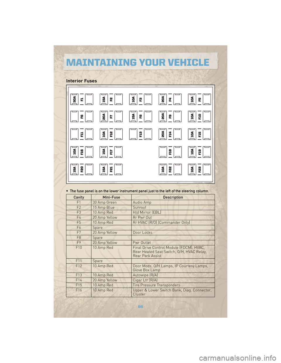
Interior Fuses
• The fuse panel is on the lower instrument panel just to the left of the steering column.
Cavity Mini-FuseDescription
F1 30 Amp Green Audio Amp
F2 15 Amp Blue Sunroof
F3 10 Amp Red Htd Mirror (EBL)
F4 20 Amp Yellow Rr Pwr Out
F5 10 Amp Red Rr HVAC (R/O) (Commander Only)
F6 Spare
F7 20 Amp Yellow Door Locks
F8 Spare
F9 20 Amp Yellow Pwr Outlet
F10 10 Amp Red Final Drive Control Module (FDCM), HVAC,
Rear Heated Seat Switch, O/H, HVAC Relay,
Rear Park Assist
F11 Spare
F12 10 Amp Red Door Mods, O/H Lamps, IP Courtesy Lamps,
Glove Box Lamp
F13 10 Amp Red Autowipe (R/A)
F14 20 Amp Yellow Cigar Ltr (R/A)
F15 10 Amp Red Tire Pressure Transponders
F16 10 Amp Red Upper & Lower Switch Bank, Diag. Connector,
Cluster
MAINTAINING YOUR VEHICLE
66
Page 69 of 78
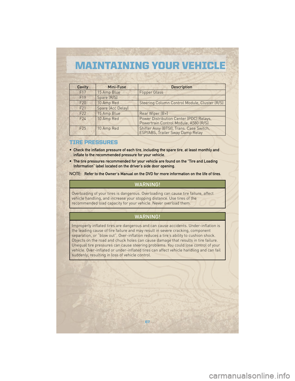
Cavity Mini-FuseDescription
F17 15 Amp Blue Flipper Glass
F19 Spare (R/S)
F20 10 Amp Red Steering Column Control Module, Cluster (R/S)
F21 Spare (Acc Delay)
F22 15 Amp Blue Rear Wiper (B+)
F24 10 Amp Red Power Distribution Center (PDC) Relays,
Powertrain Control Module, A580 (R/S)
F25 10 Amp Red Shifter Assy (BTSI), Trans. Case Switch,
ESP/ABS, Trailer Sway Damp Relay
TIRE PRESSURES
• Check the inflation pressure of each tire, including the spare tire, at least monthly and
inflate to the recommended pressure for your vehicle.
• The tire pressures recommended for your vehicle are found on the “Tire and Loading Information” label located on the driver’s side door opening.
NOTE: Refer to the Owner's Manual on the DVD for more information on the life of tires.
WARNING!
Overloading of your tires is dangerous. Overloading can cause tire failure, affect
vehicle handling, and increase your stopping distance. Use tires of the
recommended load capacity for your vehicle. Never overload them.
WARNING!
Improperly inflated tires are dangerous and can cause accidents. Under-inflation is
the leading cause of tire failure and may result in severe cracking, component
separation, or “blow out”. Over-inflation reduces a tire’s ability to cushion shock.
Objects on the road and chuck holes can cause damage that results in tire failure.
Unequal tire pressures can cause steering problems. You could lose control of your
vehicle. Over-inflated or under-inflated tires can affect vehicle handling and can fail
suddenly, resulting in loss of vehicle control.
67
MAINTAINING YOUR VEHICLE