radio controls JEEP COMMANDER 2010 1.G User Guide
[x] Cancel search | Manufacturer: JEEP, Model Year: 2010, Model line: COMMANDER, Model: JEEP COMMANDER 2010 1.GPages: 78, PDF Size: 7.31 MB
Page 3 of 78

INTRODUCTION/WELCOME
WELCOME FROM
CHRYSLER GROUP LLC.......... 2
CONTROLS AT A GLANCE
DRIVER COCKPIT.............. 4
INSTRUMENT CLUSTER .......... 6
GETTING STARTED
KEYFOB .................. 8
THEFT ALARM............... 9
SEAT BELT ................. 9
FRONT SEATS ...............10
REAR SEATS ................13
TILT/TELESCOPING STEERING
COLUMN ..................15
ADJUSTABLE PEDALS ...........16
PROGRAMMABLE FEATURES .......16
OPERATING YOUR VEHICLE
TURN SIGNAL/LIGHTS LEVER .......17
WIPER/WASHER LEVER ..........18
SPEED CONTROL LEVER .........19
ELECTRONIC RANGE SELECT (ERS) . . . 20
MANUAL CLIMATE CONTROLS ......20
AUTOMATIC TEMPERATURE CONTROLS
(ATC) ....................21
PARKSENSE
®REAR PARK ASSIST ....22
PARKVIEW®REAR BACK-UP CAMERA . . 22
POWER LIFTGATE .............23
LIFTGATE FLIPPER GLASS ........23
POWER SUNROOF .............23
WIND BUFFETING .............24
ELECTRONICS
NON-TOUCH-SCREEN RADIOS ......25
TOUCH-SCREEN RADIOS .........27
REMOTE AUDIO CONTROLS ........31
VIDEO ENTERTAINMENT SYSTEM
(VES)™ ...................31
ELECTRONIC VEHICLE INFORMATION
CENTER (EVIC) ...............33
UNIVERSAL GARAGE DOOR OPENER . . . 33
POWER INVERTER .............34
POWER OUTLET ..............35
uconnect™ phone .............35
VOICE RECOGNITION ............37
OFF-ROAD CAPABILITIES
FOUR-WHEEL DRIVE OPERATION .....38
UTILITY
INTERIOR STORAGE COMPARTMENTS . . 40
TRAILER TOWING WEIGHTS (MAXIMUM
TRAILER WEIGHT RATINGS)........41
RECREATIONAL TOWING (BEHIND
MOTORHOME, ETC.) ............42
BRAKE/TRANSMISSION INTERLOCK
MANUAL OVERRIDE ............43
WHAT TO DO IN EMERGENCIES
24 HOUR TOWING ASSISTANCE ......44
INSTRUMENT CLUSTER WARNING
LIGHTS ...................44
IF YOUR ENGINE OVERHEATS .......47
JACKING AND TIRE CHANGING ......48
JUMP-STARTING ..............51
EMERGENCY TOW HOOKS .........53
TOWING A DISABLED VEHICLE ......54
EVENT DATA RECORDER (EDR) ......55
MAINTAINING YOUR VEHICLE
OPENING THE HOOD............56
ENGINE COMPARTMENT .........57
FLUIDS AND CAPACITIES .........59
MAINTENANCE CHART ..........60
FUSES ...................62
TIRE PRESSURES .............67
WHEEL AND WHEEL TRIM CARE .....68
EXTERIOR BULBS .............68
CONSUMER ASSISTANCE
CHRYSLER GROUP LLC CUSTOMER
CENTER...................69
CHRYSLER CANADA INC. CUSTOMER
CENTER ...................69
ASSISTANCE FOR THE HEARING
IMPAIRED ..................69
PUBLICATIONS ORDERING ........69
REPORTING SAFETY DEFECTS IN
THE 50 UNITED STATES AND
WASHINGTON, D.C. ............70
TIRE WARRANTY ..............70
MOPAR ACCESSORIES
MOPAR®ACCESSORIES..........73
TABLE OF CONTENTS
Page 19 of 78

TURN SIGNAL/LIGHTS LEVER
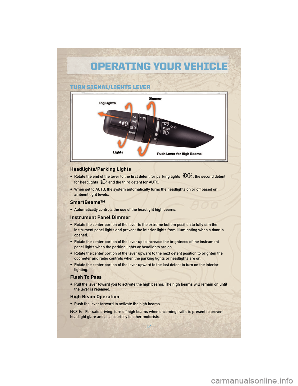
Headlights/Parking Lights
• Rotate the end of the lever to the first detent for parking lights, the second detent
for headlights
and the third detent for AUTO.
• When set to AUTO, the system automatically turns the headlights on or off based on ambient light levels.
SmartBeams™
• Automatically controls the use of the headlight high beams.
Instrument Panel Dimmer
• Rotate the center portion of the lever to the extreme bottom position to fully dim theinstrument panel lights and prevent the interior lights from illuminating when a door is
opened.
• Rotate the center portion of the lever up to increase the brightness of the instrument panel lights when the parking lights or headlights are on.
• Rotate the center portion of the lever upward to the next detent position to brighten the odometer and radio controls when the parking lights or headlights are on.
• Rotate the center portion of the lever upward to the last detent to turn on the interior lighting.
Flash To Pass
• Pull the lever toward you to activate the high beams. The high beams will remain on untilthe lever is released.
High Beam Operation
• Push the lever forward to activate the high beams.
NOTE: For safe driving, turn off high beams when oncoming traffic is present to prevent
headlight glare and as a courtesy to other motorists.
17
OPERATING YOUR VEHICLE
Page 33 of 78

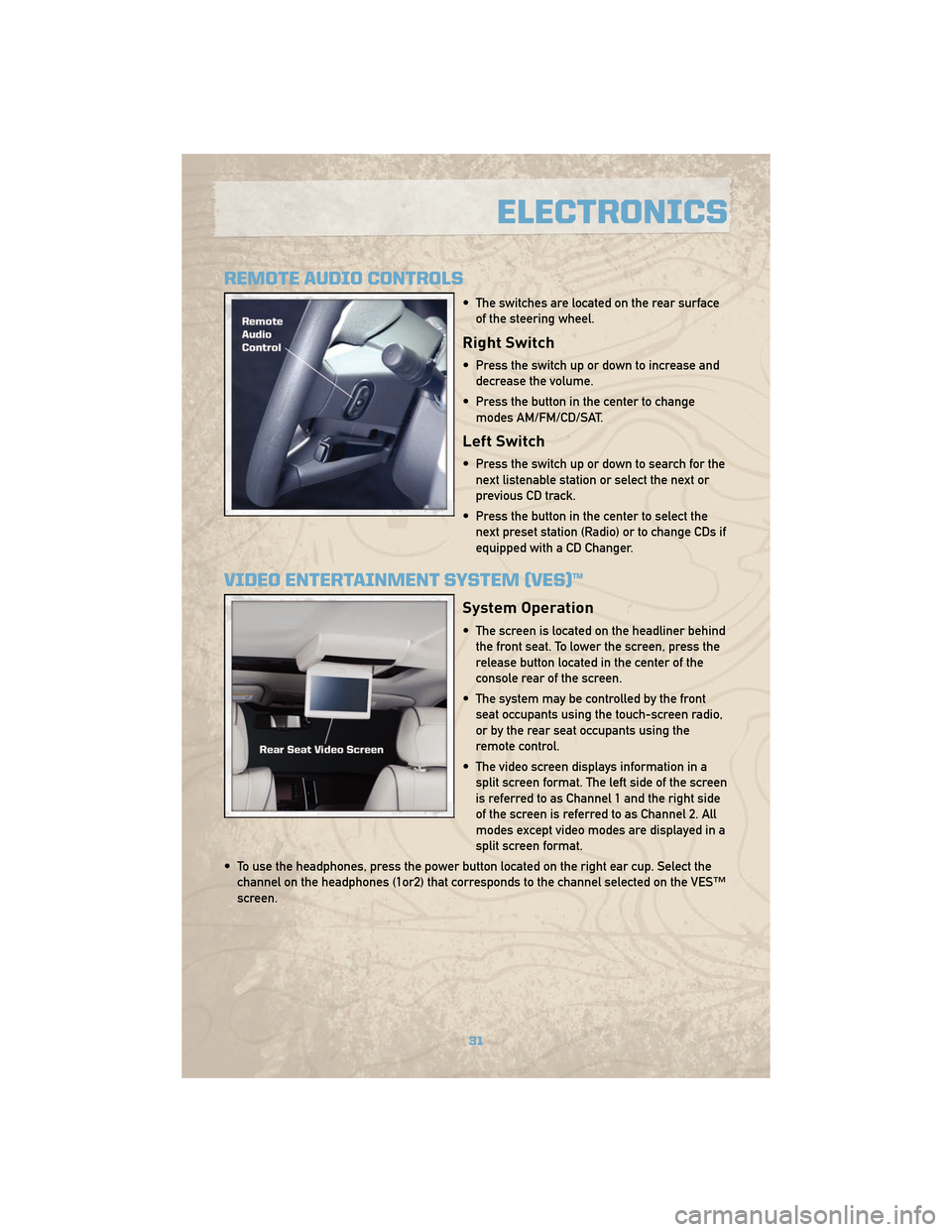
REMOTE AUDIO CONTROLS
• The switches are located on the rear surfaceof the steering wheel.
Right Switch
• Press the switch up or down to increase anddecrease the volume.
• Press the button in the center to change modes AM/FM/CD/SAT.
Left Switch
• Press the switch up or down to search for thenext listenable station or select the next or
previous CD track.
• Press the button in the center to select the next preset station (Radio) or to change CDs if
equipped with a CD Changer.
VIDEO ENTERTAINMENT SYSTEM (VES)™
System Operation
• The screen is located on the headliner behindthe front seat. To lower the screen, press the
release button located in the center of the
console rear of the screen.
• The system may be controlled by the front seat occupants using the touch-screen radio,
or by the rear seat occupants using the
remote control.
• The video screen displays information in a split screen format. The left side of the screen
is referred to as Channel 1 and the right side
of the screen is referred to as Channel 2. All
modes except video modes are displayed in a
split screen format.
• To use the headphones, press the power button located on the right ear cup. Select the channel on the headphones (1or2) that corresponds to the channel selected on the VES™
screen.
31
ELECTRONICS