battery JEEP COMPASS 2014 1.G User Guide
[x] Cancel search | Manufacturer: JEEP, Model Year: 2014, Model line: COMPASS, Model: JEEP COMPASS 2014 1.GPages: 124, PDF Size: 2.64 MB
Page 13 of 124
WARNING!
• When leaving the vehicle, always make sure the ignition is in the OFF position,remove the key fob from the vehicle, and lock your vehicle.
• Never leave children alone in a vehicle, or with access to an unlocked vehicle.
Allowing children to be in a vehicle unattended is dangerous for a number of
reasons. A child or others could be seriously or fatally injured. Children should
be warned not to touch the parking brake, brake pedal or the transmission gear
selector.
• Do not leave the Key Fob in or near the vehicle (or in a location accessible to
children), and do not leave the ignition of a vehicle equipped with Keyless
EnterNGo ™ in the ACC or ON/RUN mode. A child could operate power
windows, other controls, or move the vehicle.
REMOTE START
NOTE:
The vehicle must be equipped with an automatic transmission to be equipped with
Remote Start.
• Push the REMOTE START button
x2on the Key Fob twice within five seconds.
Pushing the REMOTE START button a third time shuts the engine off.
• To drive the vehicle, push the UNLOCK button, insert the key in the ignition and turn to the ON/RUN position.
With remote start, the engine will only run for 15 minutes (timeout) unless the
ignition key is placed in the ON/RUN position.
The vehicle must be started with the key after two consecutive timeouts.
All of the following conditions must be met before the engine will remote start:
• Gear selector in PARK
• Doors closed
• Hood closed
• Hazard switch off
• Brake switch inactive (brake pedal not pushed)
• Ignition key removed from ignition switch
• Battery at an acceptable charge level
• RKE PANIC button not pushed
• System not disabled from previous remote start event
• Vehicle theft alarm not active
GETTING STARTED
11
Page 15 of 124
To Disarm The System:
• Push the Key Fob UNLOCK button or cycle the ignition to the ON/RUN position.
The Vehicle Security Alarm is designed to protect your vehicle; however, you can create
conditions where the Vehicle Security Alarm will give you a false alarm. If one of the
previously described arming sequences has occurred, the Vehicle Security Alarm will arm
regardless of whether you are in the vehicle or not. If you remain in the vehicle and open
a door, the alarm will sound. If this occurs, disarm the Vehicle Security Alarm.
If the Vehicle Security Alarm is armed and the battery becomes disconnected the
Vehicle Security Alarm will remain armed when the battery is reconnected. The
exterior lights will flash, and the horn will sound. If this occurs, disarm the Vehicle
Security Alarm.
SEAT BELT
Be sure everyone in your vehicle is in a seat and using a seat belt properly.
• Position the lap belt across your thighs, below your abdomen. To remove slack inthe lap portion, pull up a bit on the shoulder belt. To loosen the lap belt if it is too
tight, tilt the latch plate and pull on the lap belt. A snug belt reduces the risk of
sliding under the belt in a collision.
• Position the shoulder belt on your chest so that it is comfortable and not resting on your neck. The retractor will withdraw any slack in the belt.
A shoulder belt placed behind you will not protect you from injury during a collision.
You are more likely to hit your head in a collision if you do not wear your shoulder belt.
The lap and shoulder belt are meant to be used together.
A belt that is too loose will not protect you properly. In a sudden stop you could move
too far forward, increasing the possibility of injury. Wear your seat belt snugly.
A frayed or torn belt could rip apart in a collision and leave you with no protection.
Inspect the belt system periodically, checking for cuts, frays, or loose parts. Damaged
parts must be replaced immediately. Do not disassemble or modify the system. Seat
belt assemblies must be replaced after a collision if they have been damaged (bent
retractor, torn webbing, etc.).
The seat belts for both front seating positions are equipped with pretensioning devices that
are designed to remove slack from the seat belt in the event of a collision.
A deployed pretensioner or a deployed air bag must be replaced immediately.
WARNING!
In a collision, you and your passengers can suffer much greater injuries if you are
not properly buckled up. You can strike the interior of your vehicle or other
passengers, or you can be thrown out of the vehicle. Always be sure you and others
in your vehicle are buckled up properly.
GETTING STARTED
13
Page 64 of 124
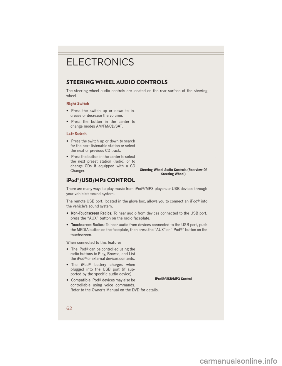
STEERING WHEEL AUDIO CONTROLS
The steering wheel audio controls are located on the rear surface of the steering
wheel.
Right Switch
• Press the switch up or down to in-crease or decrease the volume.
• Press the button in the center to change modes AM/FM/CD/SAT.
Left Switch
• Press the switch up or down to searchfor the next listenable station or select
the next or previous CD track.
• Press the button in the center to select the next preset station (radio) or to
change CDs if equipped with a CD
Changer.
iPod®/USB/MP3 CONTROL
There are many ways to play music from iPod®/MP3 players or USB devices through
your vehicle's sound system.
The remote USB port, located in the glove box, allows you to connect an iPod
®into
the vehicle's sound system.
• Non-Touchscreen Radios: To hear audio from devices connected to the USB port,
press the “AUX” button on the radio faceplate.
• Touchscreen Radios: To hear audio from devices connected to the USB port, push
the MEDIA button on the faceplate, then press the “AUX” or “iPod
®” button on the
touchscreen.
When connected to this feature:
• The iPod
®can be controlled using the
radio buttons to Play, Browse, and List
the iPod
®or external devices contents.
• The iPod
®battery charges when
plugged into the USB port (if sup-
ported by the specific audio device).
• Compatible iPod
®devices may also be
controllable using voice commands.
Refer to the Owner's Manual on the DVD for details.
Steering Wheel Audio Controls (Rearview Of Steering Wheel)
iPod®/USB/MP3 Control
ELECTRONICS
62
Page 73 of 124
Auto Door Lock
To have the doors lock automatically when the vehicle’s speed exceeds 15 mph
(24 km/h):
• Enter your vehicle and close all the doors.
• Cycle the ignition switch between LOCK and ON and then back to LOCK fourtimes, ending up in the LOCK position (do not start the engine).
• Push the power door LOCK switch to lock the doors. A single chime will indicate that programming is complete.
Sound Horn With Lock
To turn the horn chirp on or off when the doors are locked:
• Push the LOCK button and PANIC button at the same time for at least fourseconds, but no longer than 10 seconds.
• Release both buttons at the same time.
Flashing Lights With Lock
The turn signal lights flash when the doors are locked, which can be turned on or off.
To turn this feature on or off:
• Push and hold the UNLOCK button and the LOCK button at the same time for at least four seconds, but no longer than 10 seconds.
• Release both buttons at the same time.
UNIVERSAL GARAGE DOOR OPENER (HomeLink®)
• HomeLink®replaces up to three hand-held transmitters that operate devices such
as garage door openers, motorized gates, lighting or home security systems.
The HomeLink
®unit is powered by your vehicles 12 Volt battery.
• The HomeLink
®buttons that are located in the overhead console or sunvisor
designate the three different HomeLink®channels.
• The HomeLink
®indicator is located above the center button.
ELECTRONICS
71
Page 74 of 124
Before You Begin Programming HomeLink®
Ensure that your vehicle is parked outside of the garage before you begin program-
ming.
For efficient programming and accurate transmission of the radio-frequency signal,
it is recommended that a new battery be placed in the hand-held transmitter of the
device that is being programmed to the HomeLink
®system.
Erase all channels before you begin programming. To erase the channels, place the
ignition switch into the ON/RUN position, then press and hold the two outside
HomeLink
®buttons (I and III) for up to 20 seconds or until the red indicator flashes.
NOTE:
Erasing all channels should only be performed when programming HomeLink
®for
the first time. Do not erase channels when programming additional buttons.
If you have any problems, or require assistance, please call toll-free
1-800-355-3515 or, on the Internet at www.HomeLink.com for information or
assistance.
Programming A Rolling Code
NOTE:
For programming Garage Door Openers that were manufactured after 1995. These
Garage Door Openers can be identified by the “LEARN” or “TRAIN” button located
where the hanging antenna is attached to the Garage Door Opener. It is NOT the
button that is normally used to open and close the door. The name and color of the
button may vary by manufacturer.
1. Place the ignition switch into the ON/RUN position.
2. Place the hand-held transmitter 1 to 3 in (3 to 8 cm) away from the HomeLink
®
button you wish to program while keeping the HomeLink®indicator light in view.
3. Simultaneously press and hold both the HomeLink
®button you want to program
and the hand-held transmitter button.
4. Continue to hold both buttons and observe the indicator light. The HomeLink
®
indicator will flash slowly and then rapidly after HomeLink®has received the
frequency signal from the hand-held transmitter. Release both buttons after the
indicator light changes from slow to rapid.
5. At the garage door opener motor (in the garage), locate the “LEARN” or “TRAINING” button. This can usually be found where the hanging antenna wire
is attached to the garage door opener motor. Firmly press and release the
“LEARN” or “TRAINING” button.
ELECTRONICS
72
Page 94 of 124
JUMP-STARTING PROCEDURES
If your vehicle has a discharged battery it can be jump-started using a set of jumper
cables and a battery in another vehicle or by using a portable battery booster pack.
Jump-starting can be dangerous if done improperly so please follow the procedures
in this section carefully.
NOTE:
When using a portable battery booster pack follow the manufacturer’s operating
instructions and precautions.
Preparations For Jump-Start
The battery in your vehicle is located in the front of the engine compartment below
the air intake duct.
Air Intake Duct/Finger Screws
1 — Air Intake Duct
2 — Finger Screws
WHAT TO DO IN EMERGENCIES
92
Page 95 of 124
•To access the battery remove the air intake duct by turning the two finger screws,
located on the radiator support.
1. Set the parking brake, shift the auto-
matic transmission into PARK and
turn the ignition to LOCK.
2. Turn off the heater, radio, and all unnecessary electrical accessories.
3. If using another vehicle to jump-start the battery, park the vehicle within
the jumper cables reach, set the park-
ing brake and make sure the ignition
is OFF.
Jump-Starting Procedure
NOTE:
Remove Air Intake before proceeding with this Jump-Starting procedure.
1. Connect the positive (+)end of the jumper cable to the positive (+)post of the
vehicle with discharged battery.
2. Connect the opposite end of the positive (+)jumper cable to the positive (+)post
of the booster battery.
3. Connect the negative end (-)of the jumper cable to the negative (-)post of the
booster battery.
4. Connect the opposite end of the negative (-)jumper cable to a good engine ground
(exposed metal part of the discharged vehicle’s engine) away from the battery and
the fuel injection system.
5. Start the engine in the vehicle that has the booster battery, let the engine idle a few minutes, and then start the engine in the vehicle with the discharged battery.
Once the engine is started, remove the jumper cables in the reverse sequence:
1. Disconnect the negative (-)jumper cable from the engine ground of the vehicle
with the discharged battery.
2. Disconnect the negative end (-)of the jumper cable from the negative (-)post of
the booster battery.
3. Disconnect the opposite end of the positive (+)jumper cable from the positive (+)
post of the booster battery.
Battery Terminals
1 — Negative Terminal
2 — Positive Terminal
WHAT TO DO IN EMERGENCIES
93
Page 96 of 124
4. Disconnect the positive(+)end of the jumper cable from the positive (+)post of
the vehicle with discharged battery.
5. Reinstall the air intake duct.
If frequent jump-starting is required to start your vehicle you should have the battery
and charging system inspected at your authorized dealer.
CAUTION!
• Accessories that can be plugged into the vehicle power outlets draw power from the vehicle’s battery, even when not in use (i.e., cellular phones, etc.).
Eventually, if plugged in long enough, the vehicle’s battery will discharge
sufficiently to degrade battery life and/or prevent the engine from starting.
• Do not use a portable battery booster pack or any other booster source with a
system voltage greater than 12 Volts or damage to the battery, starter motor,
alternator or electrical system may occur.
• Failure to follow these procedures could result in damage to the charging
system of the booster vehicle or the discharged vehicle.
WARNING!
• Do not attempt jump-starting if the battery is frozen. It could rupture or explodeand cause personal injury.
• Take care to avoid the radiator cooling fan whenever the hood is raised. It can
start anytime the ignition switch is on. You can be injured by moving fan
blades.
• Remove any metal jewelry such as watch bands or bracelets that might make
an inadvertent electrical contact. You could be seriously injured.
• Batteries contain sulfuric acid that can burn your skin or eyes and generate
hydrogen gas which is flammable and explosive. Keep open flames or sparks
away from the battery.
• Do not allow vehicles to touch each other as this could establish a ground
connection and personal injury could result.
• Failure to follow this procedure could result in personal injury or property
damage due to battery explosion.
• Do not connect the cable to the negative post (-)of the discharged battery. The
resulting electrical spark could cause the battery to explode and could result in
personal injury.
WHAT TO DO IN EMERGENCIES
94
Page 106 of 124
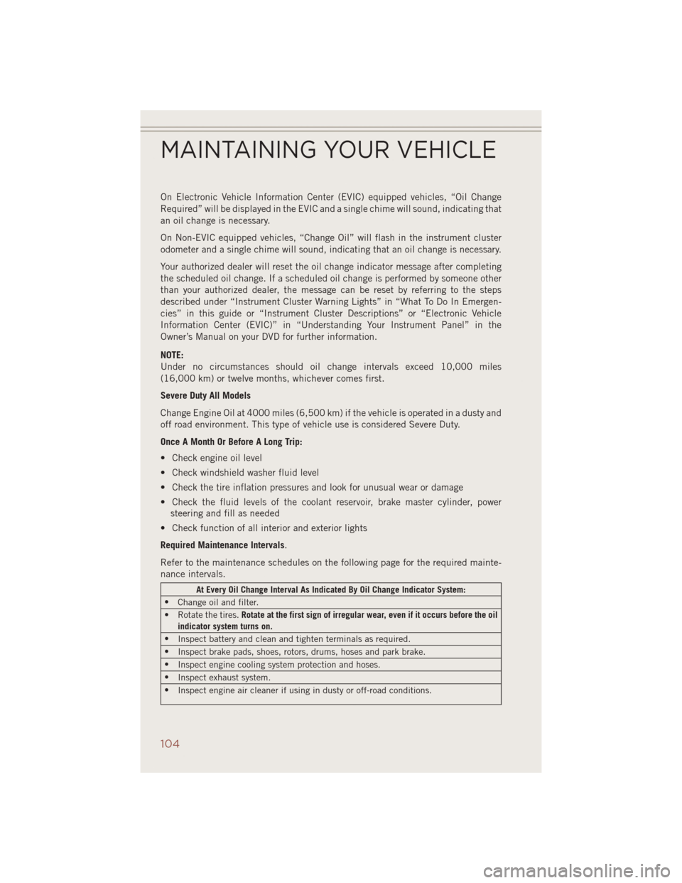
On Electronic Vehicle Information Center (EVIC) equipped vehicles, “Oil Change
Required” will be displayed in the EVIC and a single chime will sound, indicating that
an oil change is necessary.
On Non-EVIC equipped vehicles, “Change Oil” will flash in the instrument cluster
odometer and a single chime will sound, indicating that an oil change is necessary.
Your authorized dealer will reset the oil change indicator message after completing
the scheduled oil change. If a scheduled oil change is performed by someone other
than your authorized dealer, the message can be reset by referring to the steps
described under “Instrument Cluster Warning Lights” in “What To Do In Emergen-
cies” in this guide or “Instrument Cluster Descriptions” or “Electronic Vehicle
Information Center (EVIC)” in “Understanding Your Instrument Panel” in the
Owner’s Manual on your DVD for further information.
NOTE:
Under no circumstances should oil change intervals exceed 10,000 miles
(16,000 km) or twelve months, whichever comes first.
Severe Duty All Models
Change Engine Oil at 4000 miles (6,500 km) if the vehicle is operated in a dusty and
off road environment. This type of vehicle use is considered Severe Duty.
Once A Month Or Before A Long Trip:
• Check engine oil level
• Check windshield washer fluid level
• Check the tire inflation pressures and look for unusual wear or damage
• Check the fluid levels of the coolant reservoir, brake master cylinder, powersteering and fill as needed
• Check function of all interior and exterior lights
Required Maintenance Intervals.
Refer to the maintenance schedules on the following page for the required mainte-
nance intervals.
At Every Oil Change Interval As Indicated By Oil Change Indicator System:
• Change oil and filter.
• Rotate the tires. Rotate at the first sign of irregular wear, even if it occurs before the oil
indicator system turns on.
• Inspect battery and clean and tighten terminals as required.
• Inspect brake pads, shoes, rotors, drums, hoses and park brake.
• Inspect engine cooling system protection and hoses.
• Inspect exhaust system.
• Inspect engine air cleaner if using in dusty or off-road conditions.
MAINTAINING YOUR VEHICLE
104
Page 110 of 124
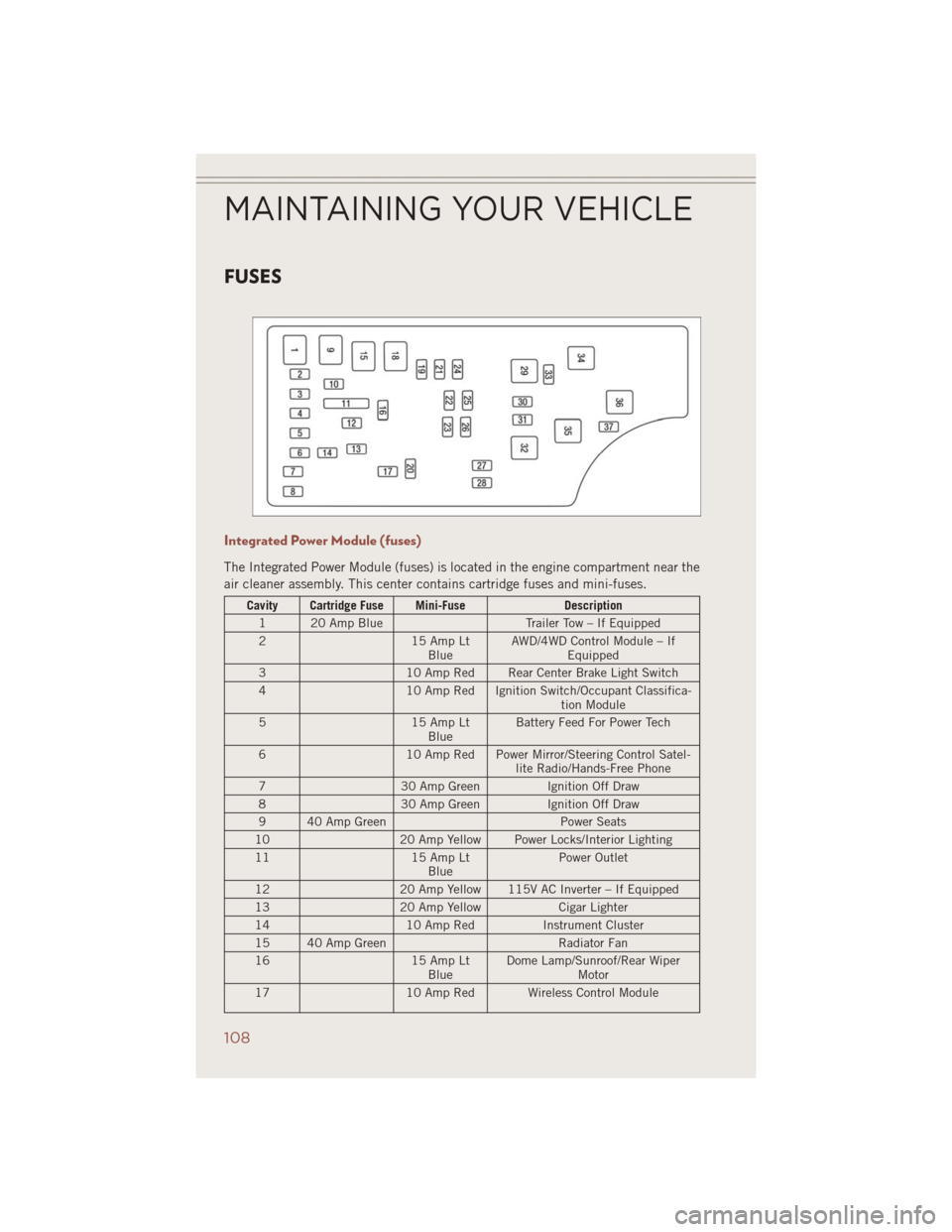
FUSES
Integrated Power Module (fuses)
The Integrated Power Module (fuses) is located in the engine compartment near the
air cleaner assembly. This center contains cartridge fuses and mini-fuses.
Cavity Cartridge Fuse Mini-FuseDescription
1 20 Amp Blue Trailer Tow – If Equipped
2 15 Amp Lt
Blue AWD/4WD Control Module – If
Equipped
3 10 Amp Red Rear Center Brake Light Switch
4 10 Amp Red Ignition Switch/Occupant Classifica-
tion Module
5 15 Amp Lt
Blue Battery Feed For Power Tech
6 10 Amp Red Power Mirror/Steering Control Satel-
lite Radio/Hands-Free Phone
7 30 Amp Green Ignition Off Draw
8 30 Amp Green Ignition Off Draw
9 40 Amp Green Power Seats
10 20 Amp Yellow Power Locks/Interior Lighting
11 15 Amp Lt
Blue Power Outlet
12 20 Amp Yellow 115V AC Inverter – If Equipped
13 20 Amp Yellow Cigar Lighter
14 10 Amp RedInstrument Cluster
15 40 Amp Green Radiator Fan
16 15 Amp Lt
Blue Dome Lamp/Sunroof/Rear Wiper
Motor
17 10 Amp Red Wireless Control Module
MAINTAINING YOUR VEHICLE
108