spare tire JEEP COMPASS 2014 1.G User Guide
[x] Cancel search | Manufacturer: JEEP, Model Year: 2014, Model line: COMPASS, Model: JEEP COMPASS 2014 1.GPages: 124, PDF Size: 2.64 MB
Page 82 of 124
ROADSIDE ASSISTANCE
Dial toll-free 1-800-521-2779 for U.S. Residents or 1-800-363-4869 for Canadian
Residents.
• Provide your name, vehicle identification number, license plate number, and yourlocation, including the telephone number from which you are calling.
• Briefly describe the nature of the problem and answer a few simple questions.
• You will be given the name of the service provider and an estimated time of arrival. If you feel you are in an “unsafe situation”, please let us know. With your consent,
we will contact local police or safety authorities.
INSTRUMENT CLUSTER WARNING LIGHTS
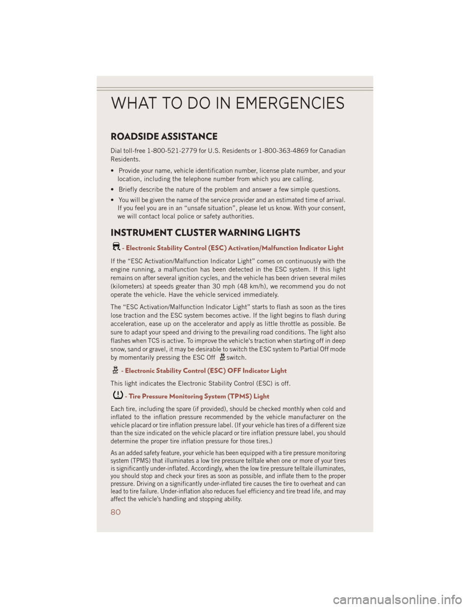
- Electronic Stability Control (ESC) Activation/Malfunction Indicator Light
If the “ESC Activation/Malfunction Indicator Light” comes on continuously with the
engine running, a malfunction has been detected in the ESC system. If this light
remains on after several ignition cycles, and the vehicle has been driven several miles
(kilometers) at speeds greater than 30 mph (48 km/h), we recommend you do not
operate the vehicle. Have the vehicle serviced immediately.
The “ESC Activation/Malfunction Indicator Light” starts to flash as soon as the tires
lose traction and the ESC system becomes active. If the light begins to flash during
acceleration, ease up on the accelerator and apply as little throttle as possible. Be
sure to adapt your speed and driving to the prevailing road conditions. The light also
flashes when TCS is active. To improve the vehicle's traction when starting off in deep
snow, sand or gravel, it may be desirable to switch the ESC system to Partial Off mode
by momentarily pressing the ESC Off
switch.
- Electronic Stability Control (ESC) OFF Indicator Light
This light indicates the Electronic Stability Control (ESC) is off.
- Tire Pressure Monitoring System (TPMS) Light
Each tire, including the spare (if provided), should be checked monthly when cold and
inflated to the inflation pressure recommended by the vehicle manufacturer on the
vehicle placard or tire inflation pressure label. (If your vehicle has tires of a different size
than the size indicated on the vehicle placard or tire inflation pressure label, you should
determine the proper tire inflation pressure for those tires.)
As an added safety feature, your vehicle has been equipped with a tire pressure monitoring
system (TPMS) that illuminates a low tire pressure telltale when one or more of your tires
is significantly under-inflated. Accordingly, when the low tire pressure telltale illuminates,
you should stop and check your tires as soon as possible, and inflate them to the proper
pressure. Driving on a significantly under-inflated tire causes the tire to overheat and can
lead to tire failure. Under-inflation also reduces fuel efficiency and tire tread life, and may
affect the vehicle’s handling and stopping ability.
WHAT TO DO IN EMERGENCIES
80
Page 88 of 124
JACKING AND TIRE CHANGING
Jack Location
The jack and jack-handle are stowed under the load floor in the cargo area.
Spare Tire Stowage
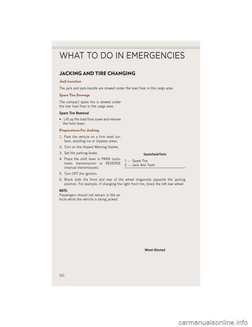
The compact spare tire is stowed under
the rear load floor in the cargo area.
Spare Tire Removal
• Lift up the load floor cover and removethe hold down.
Preparations For Jacking
1. Park the vehicle on a firm level sur-
face, avoiding ice or slippery areas.
2. Turn on the Hazard Warning flasher.
3. Set the parking brake.
4. Place the shift lever in PARK (auto- matic transmission) or REVERSE
(manual transmission).
5. Turn OFF the ignition.
6. Block both the front and rear of the wheel diagonally opposite the jacking position. For example, if changing the right front tire, block the left rear wheel.
NOTE:
Passengers should not remain in the ve-
hicle while the vehicle is being jacked.
Spare/Jack/Tools
1 — Spare Tire
2 — Jack And Tools
Wheel Blocked
WHAT TO DO IN EMERGENCIES
86
Page 89 of 124
Jacking Instructions
NOTE:
Refer to “Tires — General Information”
in “Starting And Operating” in the Own-
er's Manual on the DVD for further infor-
mation about the spare tire, it's use, and
operation.
1.
Remove the scissors jack and lug
wrench from the spare wheel as an
assembly. Turn the jack screw to the
left to loosen the lug wrench and re-
move the wrench from the jack assem-
bly.
2. Loosen, but do not remove, the wheel nuts by turning them to the left one turnwhile the wheel is still on the ground.
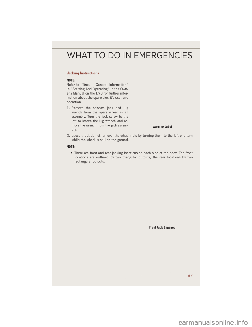
NOTE: • There are front and rear jacking locations on each side of the body. The frontlocations are outlined by two triangular cutouts, the rear locations by two
rectangular cutouts.
Warning Label
Front Jack Engaged
WHAT TO DO IN EMERGENCIES
87
Page 90 of 124
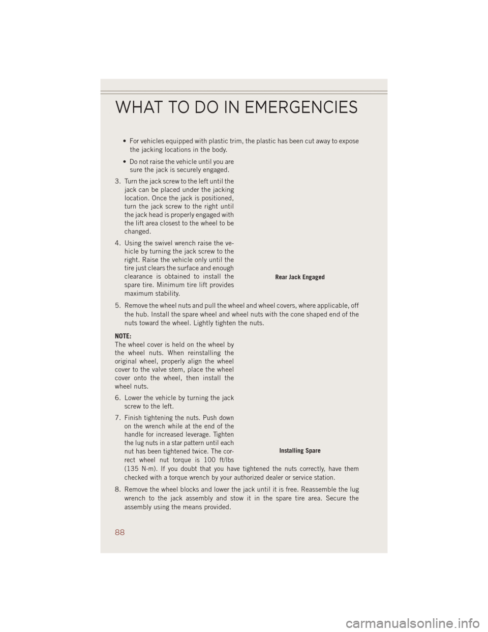
• For vehicles equipped with plastic trim, the plastic has been cut away to exposethe jacking locations in the body.
• Do not raise the vehicle until you are sure the jack is securely engaged.
3. Turn the jack screw to the left until the jack can be placed under the jacking
location. Once the jack is positioned,
turn the jack screw to the right until
the jack head is properly engaged with
the lift area closest to the wheel to be
changed.
4. Using the swivel wrench raise the ve- hicle by turning the jack screw to the
right. Raise the vehicle only until the
tire just clears the surface and enough
clearance is obtained to install the
spare tire. Minimum tire lift provides
maximum stability.
5. Remove the wheel nuts and pull the wheel and wheel covers, where applicable, off the hub. Install the spare wheel and wheel nuts with the cone shaped end of the
nuts toward the wheel. Lightly tighten the nuts.
NOTE:
The wheel cover is held on the wheel by
the wheel nuts. When reinstalling the
original wheel, properly align the wheel
cover to the valve stem, place the wheel
cover onto the wheel, then install the
wheel nuts.
6. Lower the vehicle by turning the jack screw to the left.
7.
Finish tightening the nuts. Push down
on the wrench while at the end of the
handle for increased leverage. Tighten
the lug nuts in a star pattern until each
nut has been tightened twice. The cor-
rect wheel nut torque is 100 ft/lbs
(135 N·m). If you doubt that you have tightened the nuts correctly, have them
checked with a torque wrench by your authorized dealer or service station.
8. Remove the wheel blocks and lower the jack until it is free. Reassemble the lug wrench to the jack assembly and stow it in the spare tire area. Secure the
assembly using the means provided.
Rear Jack Engaged
Installing Spare
WHAT TO DO IN EMERGENCIES
88
Page 91 of 124
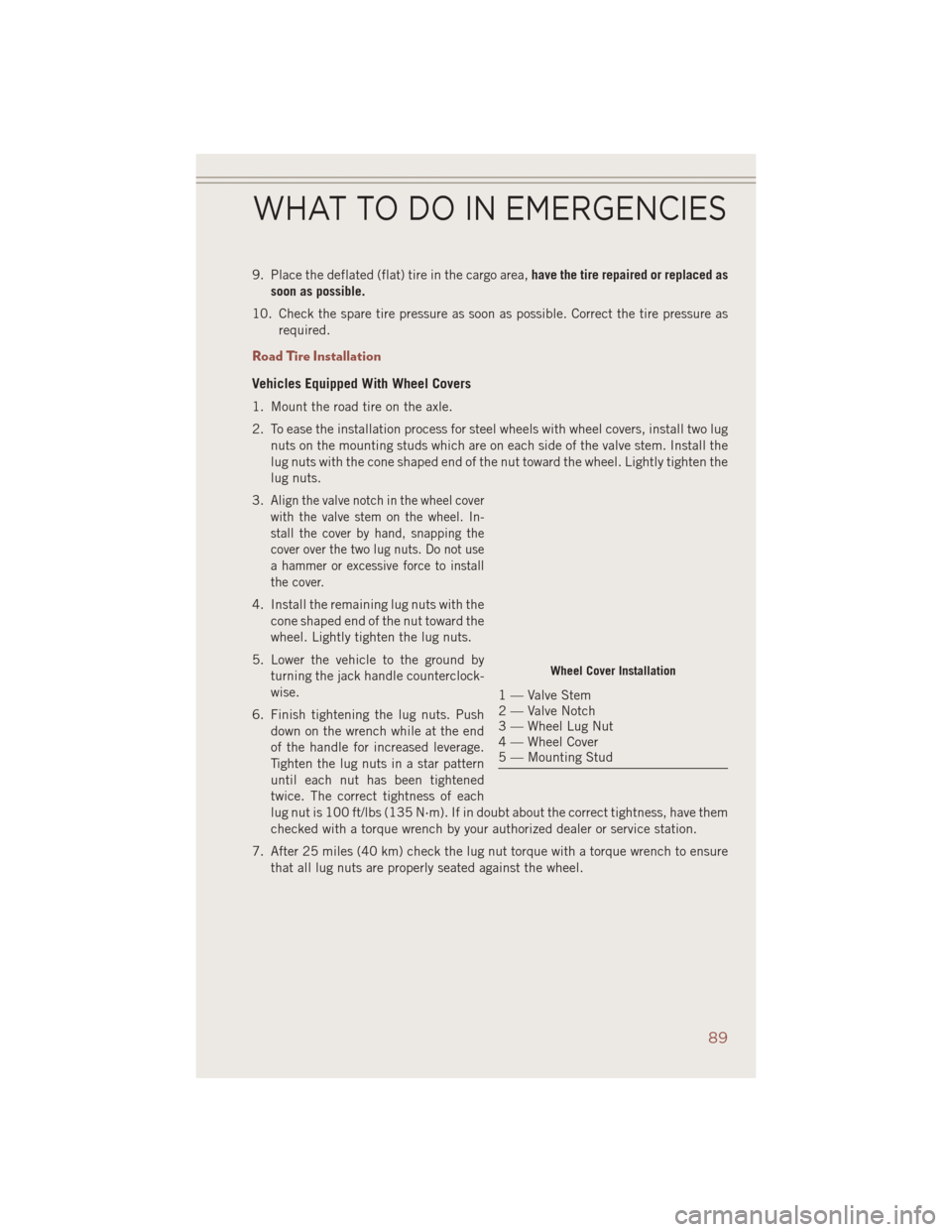
9. Place the deflated (flat) tire in the cargo area,have the tire repaired or replaced as
soon as possible.
10. Check the spare tire pressure as soon as possible. Correct the tire pressure as required.
Road Tire Installation
Vehicles Equipped With Wheel Covers
1. Mount the road tire on the axle.
2. To ease the installation process for steel wheels with wheel covers, install two lugnuts on the mounting studs which are on each side of the valve stem. Install the
lug nuts with the cone shaped end of the nut toward the wheel. Lightly tighten the
lug nuts.
3.
Align the valve notch in the wheel cover
with the valve stem on the wheel. In-
stall the cover by hand, snapping the
cover over the two lug nuts. Do not use
a hammer or excessive force to install
the cover.
4. Install the remaining lug nuts with the cone shaped end of the nut toward the
wheel. Lightly tighten the lug nuts.
5. Lower the vehicle to the ground by turning the jack handle counterclock-
wise.
6. Finish tightening the lug nuts. Push down on the wrench while at the end
of the handle for increased leverage.
Tighten the lug nuts in a star pattern
until each nut has been tightened
twice. The correct tightness of each
lug nut is 100 ft/lbs (135 N·m). If in doubt about the correct tightness, have them
checked with a torque wrench by your authorized dealer or service station.
7. After 25 miles (40 km) check the lug nut torque with a torque wrench to ensure that all lug nuts are properly seated against the wheel.
Wheel Cover Installation
1 — Valve Stem
2 — Valve Notch
3 — Wheel Lug Nut
4 — Wheel Cover
5 — Mounting Stud
WHAT TO DO IN EMERGENCIES
89
Page 92 of 124
Vehicles Without Wheel Covers
1. Mount the road tire on the axle.
2. Install the remaining lug nuts with the cone shaped end of the nut toward thewheel. Lightly tighten the lug nuts.
3. Lower the vehicle to the ground by turning the jack handle counterclockwise.
4. Finish tightening the lug nuts. Push down on the wrench while at the end of the handle for increased leverage. Tighten the lug nuts in a star pattern until each nut
has been tightened twice. The correct tightness of each lug nut is 100 ft/lbs
(135 N·m). If in doubt about the correct tightness, have them checked with a
torque wrench by your authorized dealer or service station.
5. After 25 miles (40 km) check the lug nut torque with a torque wrench to ensure that all lug nuts are properly seated against the wheel.
CAUTION!
• Do not attempt to raise the vehicle by jacking on locations other than thoseindicated in the Jacking Instructions for this vehicle.
• Be sure to mount the spare tire with the valve stem facing outward. The vehicle
could be damaged if the spare tire is mounted incorrectly.
WHAT TO DO IN EMERGENCIES
90
Page 93 of 124
WARNING!
• Being under a jacked-up vehicle is dangerous. The vehicle could slip off thejack and fall on you. You could be crushed. Never put any part of your body
under a vehicle that is on a jack. If you need to get under a raised vehicle, take
it to a service center where it can be raised on a lift.
• Never start or run the engine while the vehicle is on a jack.
• The jack is designed to be used as a tool for changing tires only. The jack
should not be used to lift the vehicle for service purposes. The vehicle should
be jacked on a firm level surface only. Avoid ice or slippery areas.
• Do not attempt to change a tire on the side of the vehicle close to moving
traffic, pull far enough off the road to avoid the danger of being hit when
operating the jack or changing the wheel.
• Carefully follow these tire changing warnings to help prevent personal injury or
damage to your vehicle:
• Always park on a firm, level surface as far from the edge of the roadwayas possible before raising the vehicle.
• Turn on the Hazard Warning flasher.
• Block the wheel diagonally opposite the wheel to be raised.
• Set the parking brake firmly and set an automatic transmission in PARK;
a manual transmission in REVERSE.
• Do not let anyone sit in the vehicle when it is on a jack.
• Do not get under the vehicle when it is on a jack.
• Only use the jack in the positions indicated and for lifting this vehicle during
a tire change.
• If working on or near a roadway, be extremely careful of motor traffic.
• To assure that spare tires, flat or inflated, are securely stowed, spares must be
stowed with the valve stem facing the ground.
• Raising the vehicle higher than necessary can make the vehicle less stable. It
could slip off the jack and hurt someone near it. Raise the vehicle only enough
to remove the tire.
• To avoid possible personal injury, handle the wheel covers with care to avoid
contact with any sharp edges.
• A loose tire or jack thrown forward in a collision or hard stop could injure the
occupants in the vehicle. Have the deflated (flat) tire repaired or replaced
immediately.
• To avoid the risk of forcing the vehicle off the jack, do not tighten the lug nuts
fully until the vehicle is lowered to the ground. Failure to follow this warning
may result in personal injury.
WHAT TO DO IN EMERGENCIES
91
Page 112 of 124
TIRE PRESSURES
Check the inflation pressure of each tire, including the spare tire, at least monthly
and inflate to the recommended pressure for your vehicle.
The tire pressures recommended for your vehicle are found on the “Tire and Loading
Information” label located on the driver’s side door opening.
NOTE:
Refer to the Owner's Manual on the DVD
for more information regarding tire warn-
ings and instructions.
WARNING!
• Overloading of your tires is dangerous. Overloading can cause tire failure,affect vehicle handling, and increase your stopping distance. Use tires of the
recommended load capacity for your vehicle. Never overload them.
• Improperly inflated tires are dangerous and can cause collisions. Under-
inflation increases tire flexing and can result in over-heating and tire failure.
Over-inflation reduces a tire’s ability to cushion shock. Objects on the road and
chuck holes can cause damage that results in tire failure. Unequal tire
pressures can cause steering problems. You could lose control of your vehicle.
Over-inflated or under-inflated tires can affect vehicle handling and can fail
suddenly, resulting in loss of vehicle control. Always drive with each tire
inflated to the recommended cold tire inflation pressure.
Tire And Loading Information Location (Example)
MAINTAINING YOUR VEHICLE
110
Page 120 of 124
Lumbar Support............20
Maintenance Record .........107
MaintenanceSchedule........103
Malfunction Indicator Light (CheckEngine) ...........82
Media Center Radio ........44,47
MOPAR
®Accessories .........114
Navigation ................55
Navigation System (Uconnect
®gps) ..........56
Navigation Voice Prompt Volume . . .56
New Vehicle Break-In Period .....25
Oil Change Indicator ..........84
Oil, Engine Capacity ..............102
Oil Pressure Light ...........83
Outlet Power ................75
Overheating, Engine ..........85
Panic Alarm ...............10
Phone (Uconnect
®) ..........63
Placard, Tire and Loading Information .............110
Power Inverter ...............74
Outlet (Auxiliary Electrical
Outlet) ...............75
Seats ................19
Steering ..............102
Power Sunroof .............33
Preparation for Jacking ........86
Programmable Electronic Features . .70
Radio Operation .....39,42,45,50
Rain Sensitive Wiper System .....27
RearSeat,Folding...........22
RearWiper/Washer...........27
Remote Keyless Entry (RKE) Arm The Alarm ...........12
Disarm The Alarm .........13
Lock The Doors ...........10
Panic Alarm ............10
Remote Keyless Entry (RKE) . . .10
Unlock The Doors .........10 Remote Starting
HowToUseRemoteStart .....11
KeyFob ...............11
Remote Starting System .....11
Remote Starting System ........11
Replacement Bulbs ..........111
Reporting Safety Defects .......113
RollOverWarning ............4
Satellite Radio (Uconnect
®studios) . . .41, 43, 46
Schedule,Maintenance .......103
Seat Belt Automatic Locking Retractor
(ALR) ................13
Child Restraints ........13,15
Energy Management Feature . . .13
Engage The Automatic Locking
Mode ................17
Lap/Shoulder Belts .........13
Seat Belt Pretensioner ......13
SeatBeltReminder ........13
Seats ...................19
Adjustment .............19
Folding Front Passenger .....21
Heated ...............23
Height Adjustment ........20
Manual ...............19
Power ................19
RearFolding ............22
Security Alarm Arm The System ..........12
Disarm The System ........13
Security Alarm ...........12
Shift Lever Override ..........95
Signals, Turn ..............27
SIRIUS Travel Link ...........58
SpareTire................86
SparkPlugs..............102
Speed Control Accel/Decel ............28
Cancel ...............29
Resume ...............29
Set .................28
Starting Remote ...............11
Steering TiltColumn .............24
INDEX
118
Page 121 of 124
Steering Wheel Audio Controls....62
Supplemental Restraint System - Airbag ................14
Tilt Steering Column ..........24
Tires...................86 Air Pressure ...........110
Changing ..............86
Jacking ...............86
SpareTire .............86
Touchscreen Radio Audio Settings ...........49
Cleaning Your Touchscreen
Radio ................55
Towing..................78 Disabled Vehicle ..........96
Towing Vehicle Behind a Motorhome..............79
Trailer Towing Trailer and Tongue Weight ....78
Trailer Weight ..............78 Transmission
Automatic .............30
Fluid ................102
TurnSignals...............27
Uconnect
®VoiceCommand......66
Vehicle Security Alarm Disarming . .13
Voice Command ............66
Voice Prompt Volume Navigation ..............56
Volume Navigation Voice Prompt .....56
Warning, Roll Over ............4
Washer Rear .................28
Washers, Windshield ..........27
WheelandWheelTrimCare.....111
Wind Buffeting .............35
Windshield Washers ..........27
Windshield Wipers ...........27
Wiper,Rear...............28
INDEX
119