light JEEP COMPASS 2015 1.G Owner's Manual
[x] Cancel search | Manufacturer: JEEP, Model Year: 2015, Model line: COMPASS, Model: JEEP COMPASS 2015 1.GPages: 132, PDF Size: 21.94 MB
Page 86 of 132
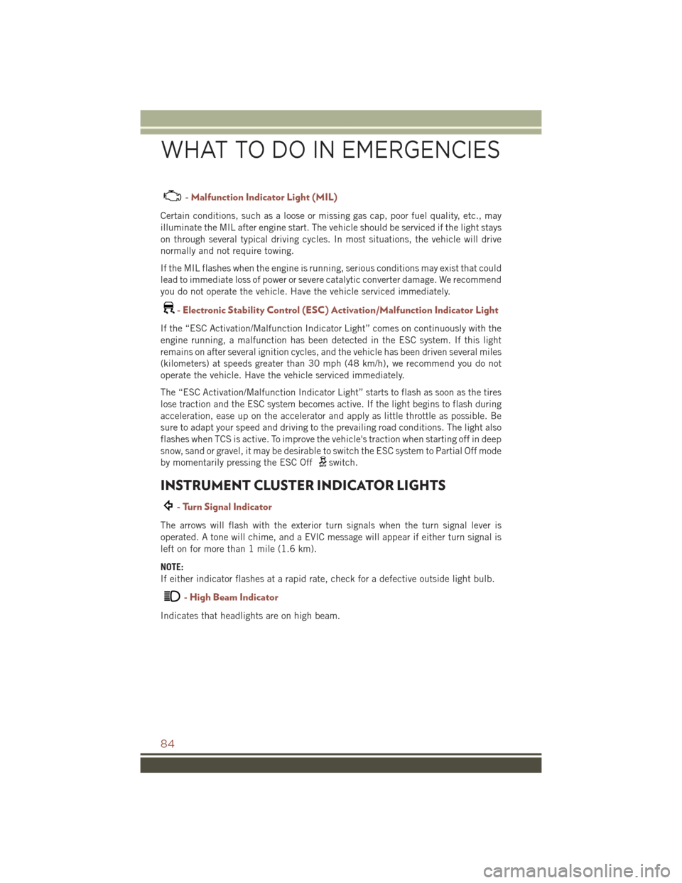
- Malfunction Indicator Light (MIL)
Certain conditions, such as a loose or missing gas cap, poor fuel quality, etc., may
illuminate the MIL after engine start. The vehicle should be serviced if the light stays
on through several typical driving cycles. In most situations, the vehicle will drive
normally and not require towing.
If the MIL flashes when the engine is running, serious conditions may exist that could
lead to immediate loss of power or severe catalytic converter damage. We recommend
you do not operate the vehicle. Have the vehicle serviced immediately.
-ElectronicStabilityControl(ESC)Activation/MalfunctionIndicatorLight
If the “ESC Activation/Malfunction Indicator Light” comes on continuously with the
engine running, a malfunction has been detected in the ESC system. If this light
remains on after several ignition cycles, and the vehicle has been driven several miles
(kilometers) at speeds greater than 30 mph (48 km/h), we recommend you do not
operate the vehicle. Have the vehicle serviced immediately.
The “ESC Activation/Malfunction Indicator Light” starts to flash as soon as the tires
lose traction and the ESC system becomes active. If the light begins to flash during
acceleration, ease up on the accelerator and apply as little throttle as possible. Be
sure to adapt your speed and driving to the prevailing road conditions. The light also
flashes when TCS is active. To improve the vehicle's traction when starting off in deep
snow, sand or gravel, it may be desirable to switch the ESC system to Partial Off mode
by momentarily pressing the ESC Offswitch.
INSTRUMENT CLUSTER INDICATOR LIGHTS
- Turn Signal Indicator
The arrows will flash with the exterior turn signals when the turn signal lever is
operated. A tone will chime, and a EVIC message will appear if either turn signal is
left on for more than 1 mile (1.6 km).
NOTE:
If either indicator flashes at a rapid rate, check for a defective outside light bulb.
- High Beam Indicator
Indicates that headlights are on high beam.
WHAT TO DO IN EMERGENCIES
84
Page 87 of 132
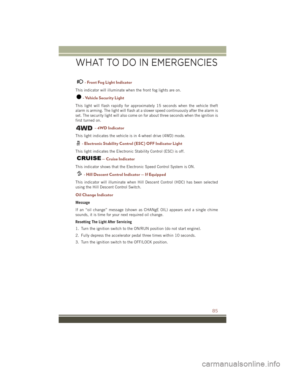
- Front Fog Light Indicator
This indicator will illuminate when the front fog lights are on.
- Vehicle Security Light
This light will flash rapidly for approximately 15 seconds when the vehicle theft
alarm is arming. The light will flash at a slower speed continuously after the alarm is
set. The security light will also come on for about three seconds when the ignition is
first turned on.
– 4WD Indicator
This light indicates the vehicle is in 4-wheel drive (4WD) mode.
- Electronic Stability Control (ESC) OFF Indicator Light
This light indicates the Electronic Stability Control (ESC) is off.
— Cruise Indicator
This indicator shows that the Electronic Speed Control System is ON.
- Hill Descent Control Indicator — If Equipped
This indicator will illuminate when Hill Descent Control (HDC) has been selected
using the Hill Descent Control Switch.
Oil Change Indicator
Message
If an “oil change” message (shown as CHANgE OIL) appears and a single chime
sounds, it is time for your next required oil change.
Resetting The Light After Servicing
1. Turn the ignition switch to the ON/RUN position (do not start engine).
2. Fully depress the accelerator pedal three times within 10 seconds.
3. Turn the ignition switch to the OFF/LOCK position.
WHAT TO DO IN EMERGENCIES
85
Page 89 of 132
AUTOMATIC TRANSMISSION OVERHEATING
During sustained high speed driving or trailer towing up long grades on hot days, the
automatic transmission oil may become too hot.
When the transmission overheat warning lightturns on, you will experience
reduced performance until the automatic transmission cools down. Once the trans-
mission has cooled down and the light turns off, you may continue to drive normally.
If the high speed is maintained, the overheating will continue to occur.
If the overheating continues, it may become necessary to stop the vehicle and run the
engine at idle with the transmission in NEUTRAL until the light turns off.
JACKING AND TIRE CHANGING
Jack Location
The jack and jack-handle are stowed under the load floor in the cargo area.
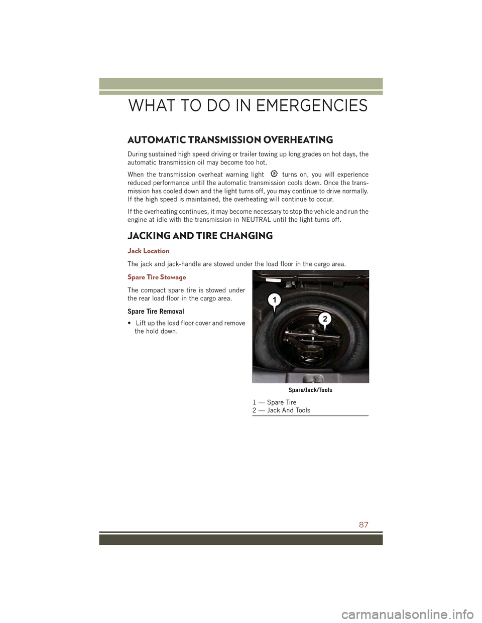
Spare Tire Stowage
The compact spare tire is stowed under
the rear load floor in the cargo area.
Spare Tire Removal
• Lift up the load floor cover and remove
the hold down.
Spare/Jack/Tools
1 — Spare Tire2 — Jack And Tools
WHAT TO DO IN EMERGENCIES
87
Page 92 of 132
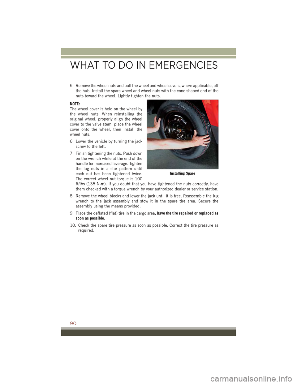
5. Remove the wheel nuts and pull the wheel and wheel covers, where applicable, off
the hub. Install the spare wheel and wheel nuts with the cone shaped end of the
nuts toward the wheel. Lightly tighten the nuts.
NOTE:
The wheel cover is held on the wheel by
the wheel nuts. When reinstalling the
original wheel, properly align the wheel
cover to the valve stem, place the wheel
cover onto the wheel, then install the
wheel nuts.
6. Lower the vehicle by turning the jack
screw to the left.
7. Finish tightening the nuts. Push down
on the wrench while at the end of the
handle for increased leverage. Tighten
the lug nuts in a star pattern until
each nut has been tightened twice.
The correct wheel nut torque is 100
ft/lbs (135 N·m). If you doubt that you have tightened the nuts correctly, have
them checked with a torque wrench by your authorized dealer or service station.
8. Remove the wheel blocks and lower the jack until it is free. Reassemble the lug
wrench to the jack assembly and stow it in the spare tire area. Secure the
assembly using the means provided.
9. Place the deflated (flat) tire in the cargo area,have the tire repaired or replaced as
soon as possible.
10. Check the spare tire pressure as soon as possible. Correct the tire pressure as
required.
Installing Spare
WHAT TO DO IN EMERGENCIES
90
Page 93 of 132
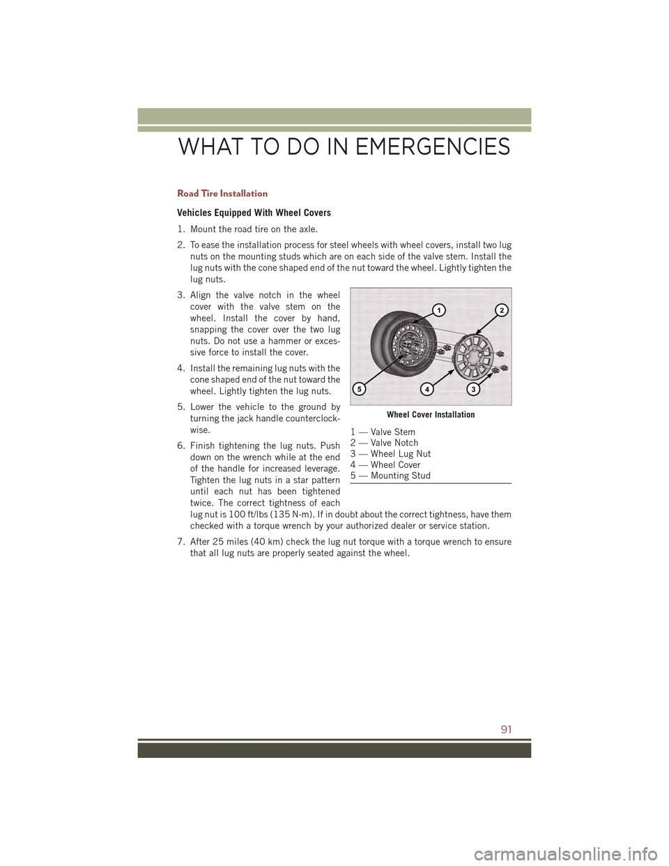
Road Tire Installation
Vehicles Equipped With Wheel Covers
1. Mount the road tire on the axle.
2. To ease the installation process for steel wheels with wheel covers, install two lug
nuts on the mounting studs which are on each side of the valve stem. Install the
lug nuts with the cone shaped end of the nut toward the wheel. Lightly tighten the
lug nuts.
3. Align the valve notch in the wheel
cover with the valve stem on the
wheel. Install the cover by hand,
snapping the cover over the two lug
nuts. Do not use a hammer or exces-
sive force to install the cover.
4. Install the remaining lug nuts with the
cone shaped end of the nut toward the
wheel. Lightly tighten the lug nuts.
5. Lower the vehicle to the ground by
turning the jack handle counterclock-
wise.
6. Finish tightening the lug nuts. Push
down on the wrench while at the end
of the handle for increased leverage.
Tighten the lug nuts in a star pattern
until each nut has been tightened
twice. The correct tightness of each
lug nut is 100 ft/lbs (135 N·m). If in doubt about the correct tightness, have them
checked with a torque wrench by your authorized dealer or service station.
7. After 25 miles (40 km) check the lug nut torque with a torque wrench to ensure
that all lug nuts are properly seated against the wheel.
Wheel Cover Installation
1 — Valve Stem2 — Valve Notch3 — Wheel Lug Nut4 — Wheel Cover5 — Mounting Stud
WHAT TO DO IN EMERGENCIES
91
Page 94 of 132
Vehicles Without Wheel Covers
1. Mount the road tire on the axle.
2. Install the remaining lug nuts with the cone shaped end of the nut toward the
wheel. Lightly tighten the lug nuts.
3. Lower the vehicle to the ground by turning the jack handle counterclockwise.
4. Finish tightening the lug nuts. Push down on the wrench while at the end of the
handle for increased leverage. Tighten the lug nuts in a star pattern until each nut
has been tightened twice. The correct tightness of each lug nut is 100 ft/lbs
(135 N·m). If in doubt about the correct tightness, have them checked with a
torque wrench by your authorized dealer or service station.
5. After 25 miles (40 km) check the lug nut torque with a torque wrench to ensure
that all lug nuts are properly seated against the wheel.
CAUTION!
• Do not attempt to raise the vehicle by jacking on locations other than those
indicated in the Jacking Instructions for this vehicle.
• Be sure to mount the spare tire with the valve stem facing outward. The vehicle
could be damaged if the spare tire is mounted incorrectly.
WHAT TO DO IN EMERGENCIES
92
Page 110 of 132
MAINTENANCE PROCEDURES
For information on the maintenance procedures for your vehicle, please refer to
“Maintenance Procedures” in “Maintaining Your Vehicle” in your Owner’s Manual or
applicable supplement on the DVD for further details.
MAINTENANCE SCHEDULE
Your vehicle is equipped with an automatic oil change indicator system. The oil
change indicator system will remind you that it is time to take your vehicle in for
scheduled maintenance.
Based on engine operation conditions, the oil change indicator message will
illuminate. This means that service is required for your vehicle. Operating conditions
such as frequent short-trips, trailer tow, extremely hot or cold ambient temperatures
will influence when the “Change Oil” or “Oil Change Required” message is dis-
played. Severe Operating Conditions can cause the change oil message to illuminate
as early as 3,500 miles (5,600 km) since last reset. Have your vehicle serviced as
soon as possible, within the next 500 miles (805 km).
On Electronic Vehicle Information Center (EVIC) equipped vehicles, “Oil Change
Required” will be displayed in the EVIC and a single chime will sound, indicating that
an oil change is necessary.
On Non-EVIC equipped vehicles, “Change Oil” will flash in the instrument cluster
odometer and a single chime will sound, indicating that an oil change is necessary.
Your authorized dealer will reset the oil change indicator message after completing
the scheduled oil change. If a scheduled oil change is performed by someone other
than your authorized dealer, the message can be reset by referring to the steps
described under “Instrument Cluster Warning Lights” in “What To Do In Emergen-
cies” in this guide or “Instrument Cluster Descriptions” or “Electronic Vehicle
Information Center (EVIC)” in “Understanding Your Instrument Panel” in the
Owner’s Manual on your DVD for further information.
NOTE:
Under no circumstances should oil change intervals exceed 10,000 miles
(16,000 km) or twelve months, whichever comes first.
MAINTAINING YOUR VEHICLE
108
Page 111 of 132
Severe Duty All Models
Change Engine Oil at 4000 miles (6,500 km) if the vehicle is operated in a dusty and
off road environment. This type of vehicle use is considered Severe Duty.
Once A Month Or Before A Long Trip:
• Check engine oil level
• Check windshield washer fluid level
• Check the tire inflation pressures and look for unusual wear or damage
• Check the fluid levels of the coolant reservoir, brake master cylinder, power
steering and fill as needed
• Check function of all interior and exterior lights
Required Maintenance Intervals.
Refer to the maintenance schedules on the following page for the required mainte-
nance intervals.
At Every Oil Change Interval As Indicated By Oil Change Indicator System:
•Change oil and filter.
• Rotate the tires.Rotate at the first sign of irregular wear, even if it occurs before the oil
indicator system turns on.
•Inspect battery and clean and tighten terminals as required.
•Inspect brake pads, shoes, rotors, drums, hoses and park brake.
•Inspect engine cooling system protection and hoses.
•Inspect exhaust system.
•Inspect engine air cleaner if using in dusty or off-road conditions.
MAINTAINING YOUR VEHICLE
109
Page 115 of 132
FUSES
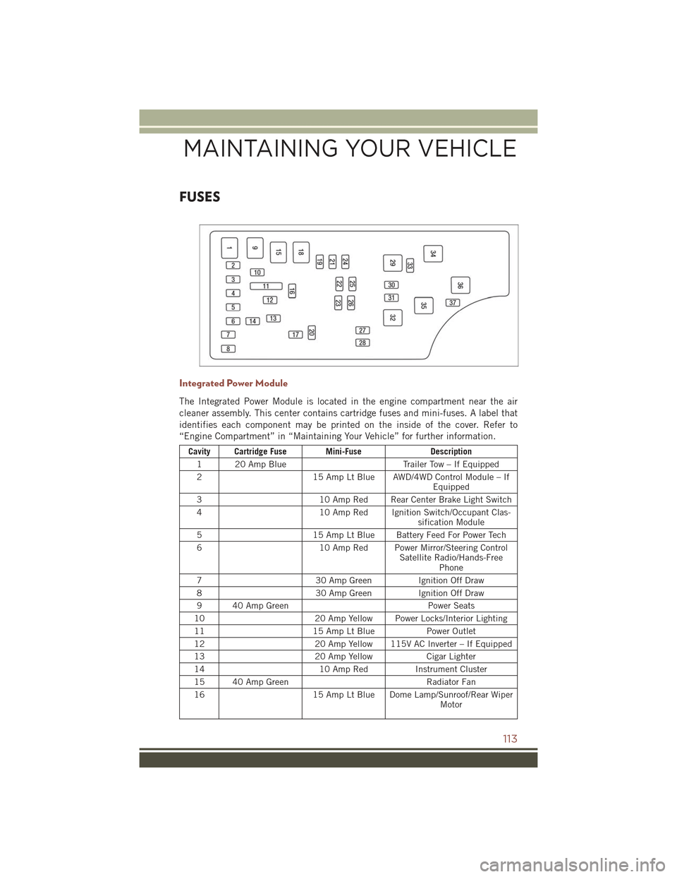
Integrated Power Module
The Integrated Power Module is located in the engine compartment near the air
cleaner assembly. This center contains cartridge fuses and mini-fuses. A label that
identifies each component may be printed on the inside of the cover. Refer to
“Engine Compartment” in “Maintaining Your Vehicle” for further information.
Cavity Cartridge Fuse Mini-FuseDescription
120AmpBlueTr a i l e r To w – I f E q u i p p e d
215 Amp Lt Blue AWD/4WD Control Module – IfEquipped
310 Amp Red Rear Center Brake Light Switch
410 Amp Red Ignition Switch/Occupant Clas-sification Module
515 Amp Lt Blue Battery Feed For Power Tech
610 Amp Red Power Mirror/Steering ControlSatellite Radio/Hands-FreePhone
730 Amp GreenIgnition Off Draw
830 Amp GreenIgnition Off Draw
940AmpGreenPower Seats
1020 Amp Yellow Power Locks/Interior Lighting
1115 Amp Lt BluePower Outlet
1220 Amp Yellow 115V AC Inverter – If Equipped
1320 Amp YellowCigar Lighter
1410 Amp RedInstrument Cluster
15 40 Amp GreenRadiator Fan
1615 Amp Lt Blue Dome Lamp/Sunroof/Rear WiperMotor
MAINTAINING YOUR VEHICLE
113
Page 120 of 132
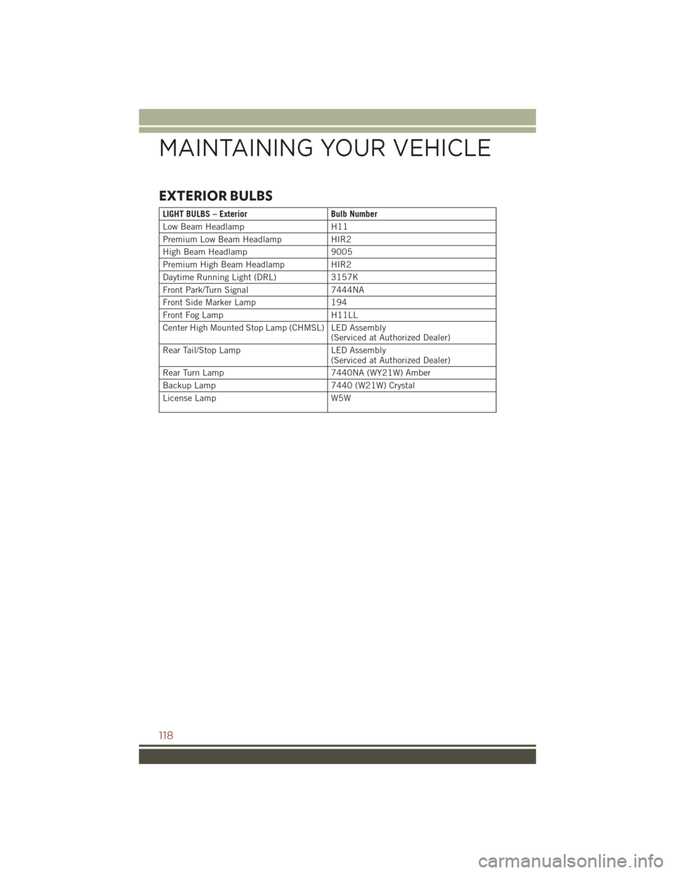
EXTERIOR BULBS
LIGHT BULBS – ExteriorBulb Number
Low Beam HeadlampH11
Premium Low Beam HeadlampHIR2
High Beam Headlamp9005
Premium High Beam HeadlampHIR2
Daytime Running Light (DRL)3157K
Front Park/Turn Signal7444NA
Front Side Marker Lamp194
Front Fog LampH11LL
Center High Mounted Stop Lamp (CHMSL) LED Assembly(Serviced at Authorized Dealer)
Rear Tail/Stop LampLED Assembly(Serviced at Authorized Dealer)
Rear Turn Lamp7440NA (WY21W) Amber
Backup Lamp7440 (W21W) Crystal
License LampW5W
MAINTAINING YOUR VEHICLE
118