brake JEEP COMPASS 2015 1.G User Guide
[x] Cancel search | Manufacturer: JEEP, Model Year: 2015, Model line: COMPASS, Model: JEEP COMPASS 2015 1.GPages: 132, PDF Size: 21.94 MB
Page 5 of 132
VEHICLES SOLD IN CANADA
With respect to any vehicles sold in Canada, the name Chrysler Group LLC shall be
deemed to be deleted and the name Chrysler Canada Inc. used in substitution.
WARNING!
• Pedals that cannot move freely can cause loss of vehicle control and increase
the risk of serious personal injury.
• Always make sure that objects cannot fall into the driver foot well while the
vehicle is moving. Objects can become trapped under the brake pedal and
accelerator pedal causing a loss of vehicle control.
• Failure to properly follow floor mat installation or mounting can cause inter-
ference with the brake pedal and accelerator pedal operation causing loss of
control of the vehicle.
• Never leave children alone in a vehicle, or with access to an unlocked vehicle.
Allowing children to be in a vehicle unattended is dangerous for a number of
reasons. A child or others could be seriously or fatally injured. Children should
be warned not to touch the parking brake, brake pedal or the shift lever/
transmission gear selector.
• Do not leave the key fob in or near the vehicle, or in a location accessible to
children, and do not leave the ignition of a vehicle equipped with Keyless
Enter-N-Go in the ACC or ON/RUN mode. A child could operate power
windows, other controls, or move the vehicle.
• Never use the ‘PARK’ position as a substitute for the parking brake. Always
apply the parking brake fully when parked to guard against vehicle movement
and possible injury or damage.
• Refer to your Owner's Manual on the DVD for further details.
INTRODUCTION/WELCOME
3
Page 6 of 132
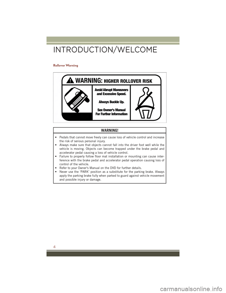
Rollover Warning
WARNING!
• Pedals that cannot move freely can cause loss of vehicle control and increase
the risk of serious personal injury.
• Always make sure that objects cannot fall into the driver foot well while the
vehicle is moving. Objects can become trapped under the brake pedal and
accelerator pedal causing a loss of vehicle control.
• Failure to properly follow floor mat installation or mounting can cause inter-
ference with the brake pedal and accelerator pedal operation causing loss of
control of the vehicle.
• Refer to your Owner's Manual on the DVD for further details.
• Never use the ‘PARK’ position as a substitute for the parking brake. Always
apply the parking brake fully when parked to guard against vehicle movement
and possible injury or damage.
INTRODUCTION/WELCOME
4
Page 13 of 132
WARNING!
• When leaving the vehicle, always make sure the ignition is in the OFF position,
remove the key fob from the vehicle, and lock your vehicle.
• Never leave children alone in a vehicle, or with access to an unlocked vehicle.
Allowing children to be in a vehicle unattended is dangerous for a number of
reasons. A child or others could be seriously or fatally injured. Children should
be warned not to touch the parking brake, brake pedal or the transmission gear
selector.
• Do not leave the Key Fob in or near the vehicle (or in a location accessible to
children). A child could operate power windows, other controls, or move the
vehicle.
REMOTE START
NOTE:
The vehicle must be equipped with an automatic transmission to be equipped with
Remote Start.
• Push the REMOTE START buttonx2on the Key Fob twice within five seconds.
Pushing the REMOTE START button a third time shuts the engine off.
• To drive the vehicle, push the UNLOCK button, insert the key in the ignition and
turn to the ON/RUN position.
With remote start, the engine will only run for 15 minutes (timeout) unless the
ignition key is placed in the ON/RUN position.
The vehicle must be started with the key after two consecutive timeouts.
All of the following conditions must be met before the engine will remote start:
• Gear selector in PARK
• Doors closed
• Hood closed
• Hazard switch off
• Brake switch inactive (brake pedal not pressed)
• Ignition key removed from ignition switch
• Battery at an acceptable charge level
• RKE PANIC button not pressed
• System not disabled from previous remote start event
• Vehicle theft alarm not active
GETTING STARTED
11
Page 32 of 132
Resume
• To resume a previously selected set speed in memory, push the RES + button and
release.
Cancel
• Push the CANCEL button, or apply the brakes to cancel the set speed and
maintain the set speed memory.
• Push the ON/OFF button to turn the system off and erase the set speed memory.
WARNING!
• Leaving the Electronic Speed Control system on when not in use is dangerous.
You could accidentally set the system or cause it to go faster than you want. You
could lose control and have a collision. Always leave the Electronic Speed
Control system off when you are not using it.
• Electronic Speed Control can be dangerous where the system cannot maintain
a constant speed. Your vehicle could go too fast for the conditions, and you
could lose control. A collision could be the result. Do not use Electronic Speed
Control in heavy traffic or on roads that are winding, icy, snow-covered or
slippery.
PARKVIEW® REAR BACK-UP CAMERA
You can see an on-screen image of the rear of your vehicle whenever the shift lever is
put into REVERSE. The ParkView®Rear Back-Up Camera image will be displayed on
the radio display screen, located on the center stack of the instrument panel.
If the radio display screen appears foggy, clean the camera lens located on the
liftgate.
Refer to your Owner's Manual on the DVD for further details.
WARNING!
Drivers must be careful when backing up; even when using the ParkView®Rear
Back-Up Camera. Always check carefully behind your vehicle, and be sure to
check for pedestrians, animals, other vehicles, obstructions, or blind spots before
backing up. You must continue to pay attention while backing up. Failure to do so
can result in serious injury or death.
OPERATING YOUR VEHICLE
30
Page 79 of 132
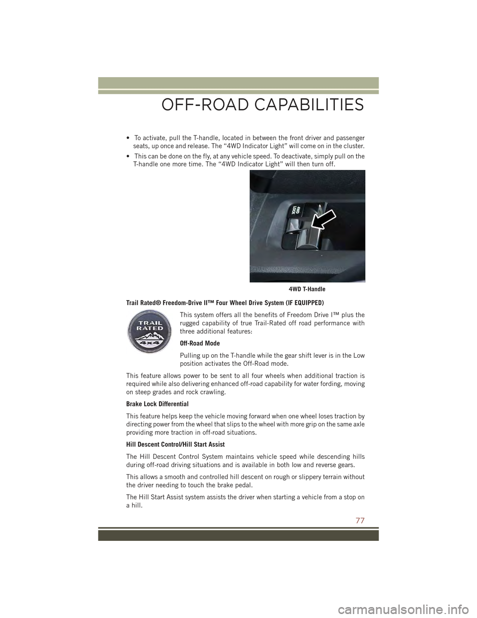
• To activate, pull the T-handle, located in between the front driver and passenger
seats, up once and release. The “4WD Indicator Light” will come on in the cluster.
• This can be done on the fly, at any vehicle speed. To deactivate, simply pull on the
T-handle one more time. The “4WD Indicator Light” will then turn off.
Trail Rated® Freedom-Drive II™ Four Wheel Drive System (IF EQUIPPED)
This system offers all the benefits of Freedom Drive I™ plus the
rugged capability of true Trail-Rated off road performance with
three additional features:
Off-Road Mode
Pulling up on the T-handle while the gear shift lever is in the Low
position activates the Off-Road mode.
This feature allows power to be sent to all four wheels when additional traction is
required while also delivering enhanced off-road capability for water fording, moving
on steep grades and rock crawling.
Brake Lock Differential
This feature helps keep the vehicle moving forward when one wheel loses traction by
directing power from the wheel that slips to the wheel with more grip on the same axle
providing more traction in off-road situations.
Hill Descent Control/Hill Start Assist
The Hill Descent Control System maintains vehicle speed while descending hills
during off-road driving situations and is available in both low and reverse gears.
This allows a smooth and controlled hill descent on rough or slippery terrain without
the driver needing to touch the brake pedal.
The Hill Start Assist system assists the driver when starting a vehicle from a stop on
a hill.
4WD T-Handle
OFF-ROAD CAPABILITIES
77
Page 82 of 132
ROADSIDE ASSISTANCE
Dial toll-free 1-800-521-2779 for U.S. Residents or 1-800-363-4869 for Canadian
Residents.
• Provide your name, vehicle identification number, license plate number, and your
location, including the telephone number from which you are calling.
• Briefly describe the nature of the problem and answer a few simple questions.
• You will be given the name of the service provider and an estimated time of arrival.
If you feel you are in an “unsafe situation”, please let us know. With your consent,
we will contact local police or safety authorities.
INSTRUMENT CLUSTER WARNING LIGHTS
- Low Fuel Warning Light
This warning light indicates when the fuel level reaches approximately 2.0 gal (7.8 L),
this light will turn on and a single chime will sound.
- Oil Pressure Warning Light
This light indicates low engine oil pressure. If the light turns on while driving, stop
the vehicle and shut off the engine as soon as possible. A chime will sound when this
light turns on.
We recommend you do not operate the vehicle or engine damage will occur. Have the
vehicle serviced immediately.
- Anti-Lock Brake (ABS) Light
This light monitors the Anti-Lock Brake System (ABS).
If the light is not on during starting, stays on, or turns on while driving, we
recommend you contact the nearest authorized dealer and have the vehicle serviced
immediately.
-ChargingSystemLight
This light shows the status of the electrical charging system. If the charging system
light remains on, it means that the vehicle is experiencing a problem with the
charging system.
We recommend you do not continue driving if the charging system light is on. Have
the vehicle serviced immediately.
- Air Bag Warning Light
If the light is not on during starting, stays on, or turns on while driving, have the
vehicle serviced by an authorized dealer immediately.
WHAT TO DO IN EMERGENCIES
80
Page 84 of 132
When the system detects a malfunction, the telltale will flash for approximately one
minute and then remain continuously illuminated. This sequence will continue upon
subsequent vehicle start-ups as long as the malfunction exists. When the malfunc-
tion indicator is illuminated, the system may not be able to detect or signal low tire
pressure as intended. TPMS malfunctions may occur for a variety of reasons,
including the installation of replacement or alternate tires or wheels on the vehicle
that prevent the TPMS from functioning properly. Always check the TPMS malfunc-
tion telltale after replacing one or more tires or wheels on your vehicle to ensure that
the replacement or alternate tires and wheels allow the TPMS to continue to function
properly.
NOTE:
Tire pressures change by approximately 1 psi (7 kPa) per 12° F (7° C) of air
temperature change. Keep this in mind when checking tire pressure inside a garage,
especially in the Winter. Example: If garage temperature is 68°F (20°C) and the
outside temperature is 32°F (0°C), then the cold tire inflation pressure should be
increased by 3 psi (21 kPa), which equals 1 psi (7 kPa) for every 12°F (7°C) for this
outside temperature condition.
CAUTION!
The TPMS has been optimized for the original equipment tires and wheels. TPMS
pressures and warning have been established for the tire size equipped on your
vehicle. Undesirable system operation or sensor damage may result when using
replacement equipment that is not of the same size, type, and/or style. Aftermar-
ket wheels can cause sensor damage. Do not use tire sealant from a can, or
balance beads if your vehicle is equipped with a TPMS, as damage to the sensors
may result.
- Brake Warning Light
The Brake Warning light illuminates when there is either a system malfunction or the
parking brake is applied. If the light is on and the parking brake is not applied, it
indicates a possible brake hydraulic malfunction, brake booster problem or an
Anti-Lock Brake System problem.
Please have your vehicle serviced immediately.
WARNING!
Driving a vehicle with the red brake light on is dangerous. Part of the brake system
may have failed. It will take longer to stop the vehicle. You could have a collision.
Have the vehicle checked immediately.
WHAT TO DO IN EMERGENCIES
82
Page 90 of 132
Preparations For Jacking
1. Park the vehicle on a firm level surface, avoiding ice or slippery areas.
2. Turn on the Hazard Warning flasher.
3. Set the parking brake.
4. Place the shift lever in PARK (automatic transmission) or REVERSE (manual
transmission).
5. Turn OFF the ignition.
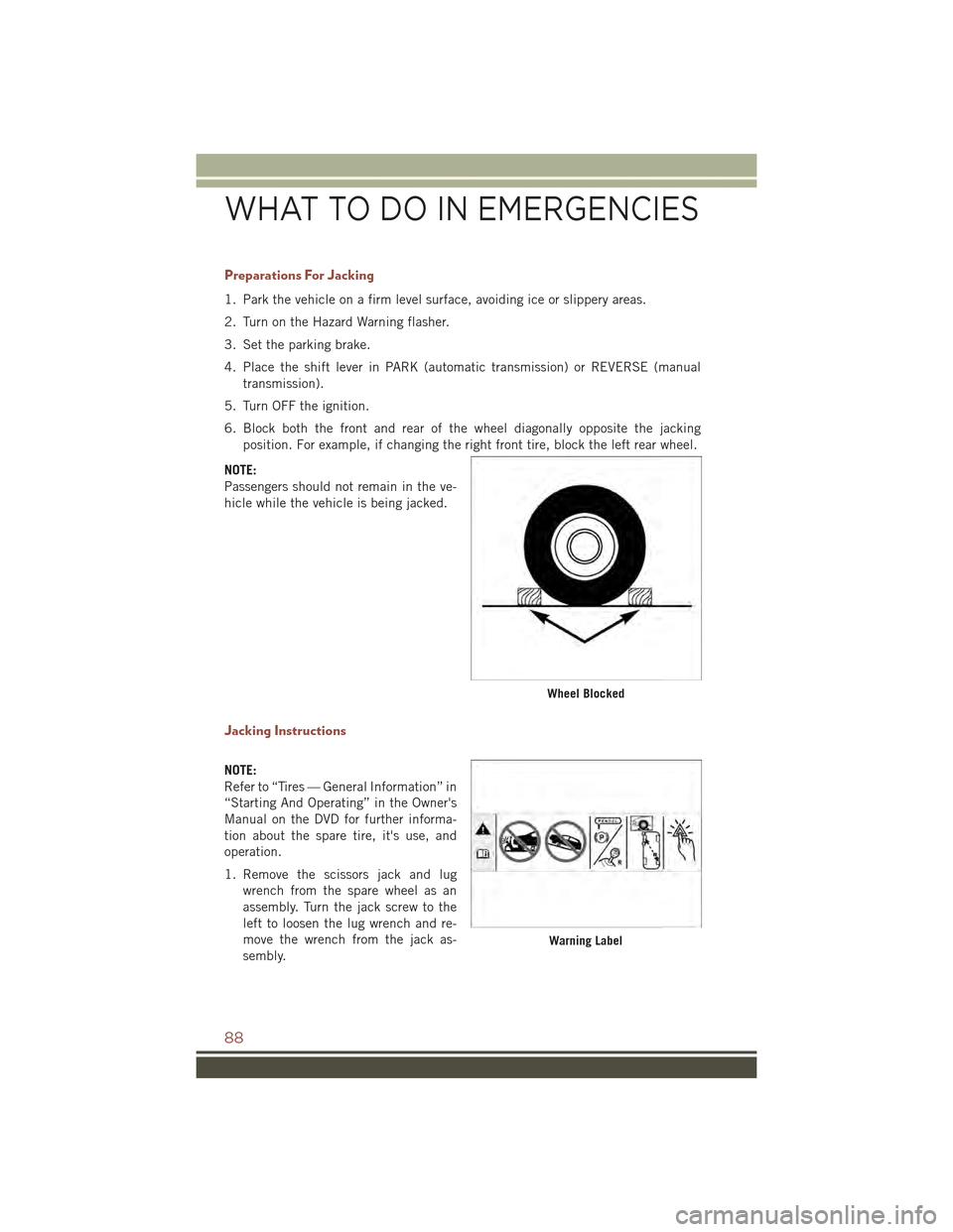
6. Block both the front and rear of the wheel diagonally opposite the jacking
position. For example, if changing the right front tire, block the left rear wheel.
NOTE:
Passengers should not remain in the ve-
hicle while the vehicle is being jacked.
Jacking Instructions
NOTE:
Refer to “Tires — General Information” in
“Starting And Operating” in the Owner's
Manual on the DVD for further informa-
tion about the spare tire, it's use, and
operation.
1. Remove the scissors jack and lug
wrench from the spare wheel as an
assembly. Turn the jack screw to the
left to loosen the lug wrench and re-
move the wrench from the jack as-
sembly.
Wheel Blocked
Warning Label
WHAT TO DO IN EMERGENCIES
88
Page 95 of 132
WARNING!
• Being under a jacked-up vehicle is dangerous. The vehicle could slip off the
jack and fall on you. You could be crushed. Never put any part of your body
under a vehicle that is on a jack. If you need to get under a raised vehicle, take
it to a service center where it can be raised on a lift.
• Never start or run the engine while the vehicle is on a jack.
• The jack is designed to be used as a tool for changing tires only. The jack
should not be used to lift the vehicle for service purposes. The vehicle should
be jacked on a firm level surface only. Avoid ice or slippery areas.
• Do not attempt to change a tire on the side of the vehicle close to moving
traffic, pull far enough off the road to avoid the danger of being hit when
operating the jack or changing the wheel.
• Carefully follow these tire changing warnings to help prevent personal injury or
damage to your vehicle:
• Always park on a firm, level surface as far from the edge of the roadway
as possible before raising the vehicle.
• Turn on the Hazard Warning flasher.
• Block the wheel diagonally opposite the wheel to be raised.
• Set the parking brake firmly and set an automatic transmission in PARK;
a manual transmission in REVERSE.
• Do not let anyone sit in the vehicle when it is on a jack.
• Do not get under the vehicle when it is on a jack.
• Only use the jack in the positions indicated and for lifting this vehicle during
a tire change.
• If working on or near a roadway, be extremely careful of motor traffic.
• To assure that spare tires, flat or inflated, are securely stowed, spares must be
stowed with the valve stem facing the ground.
• Raising the vehicle higher than necessary can make the vehicle less stable. It
could slip off the jack and hurt someone near it. Raise the vehicle only enough
to remove the tire.
• To avoid possible personal injury, handle the wheel covers with care to avoid
contact with any sharp edges.
• A loose tire or jack thrown forward in a collision or hard stop could injure the
occupants in the vehicle. Have the deflated (flat) tire repaired or replaced
immediately.
• To avoid the risk of forcing the vehicle off the jack, do not tighten the lug nuts
fully until the vehicle is lowered to the ground. Failure to follow this warning
may result in personal injury.
WHAT TO DO IN EMERGENCIES
93
Page 97 of 132
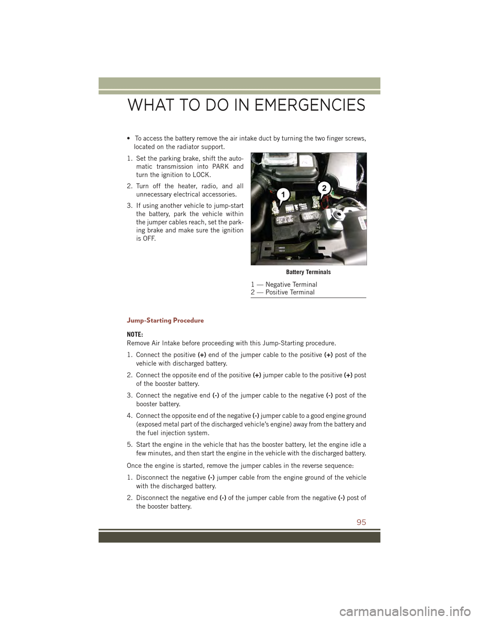
• To access the battery remove the air intake duct by turning the two finger screws,
located on the radiator support.
1. Set the parking brake, shift the auto-
matic transmission into PARK and
turn the ignition to LOCK.
2. Turn off the heater, radio, and all
unnecessary electrical accessories.
3. If using another vehicle to jump-start
the battery, park the vehicle within
the jumper cables reach, set the park-
ing brake and make sure the ignition
is OFF.
Jump-Starting Procedure
NOTE:
Remove Air Intake before proceeding with this Jump-Starting procedure.
1. Connect the positive(+)end of the jumper cable to the positive(+)post of the
vehicle with discharged battery.
2. Connect the opposite end of the positive(+)jumper cable to the positive(+)post
of the booster battery.
3. Connect the negative end(-)of the jumper cable to the negative(-)post of the
booster battery.
4. Connect the opposite end of the negative(-)jumper cable to a good engine ground
(exposed metal part of the discharged vehicle’s engine) away from the battery and
the fuel injection system.
5. Start the engine in the vehicle that has the booster battery, let the engine idle a
few minutes, and then start the engine in the vehicle with the discharged battery.
Once the engine is started, remove the jumper cables in the reverse sequence:
1. Disconnect the negative(-)jumper cable from the engine ground of the vehicle
with the discharged battery.
2. Disconnect the negative end(-)of the jumper cable from the negative(-)post of
the booster battery.
Battery Terminals
1 — Negative Terminal2 — Positive Terminal
WHAT TO DO IN EMERGENCIES
95