light JEEP COMPASS 2015 1.G User Guide
[x] Cancel search | Manufacturer: JEEP, Model Year: 2015, Model line: COMPASS, Model: JEEP COMPASS 2015 1.GPages: 132, PDF Size: 21.94 MB
Page 3 of 132
INTRODUCTION/WELCOME
WELCOME FROM CHRYSLERGROUP LLC.................. 2
CONTROLS AT A GLANCE
DRIVER COCKPIT.............. 6INSTRUMENT CLUSTER.......... 8
GETTING STARTED
KEY FOB . . . . . . . . . . . . . . . . . . . 10REMOTE START............... 11VEHICLE SECURITY ALARM....... 12SEAT BELT SYSTEMS........... 13SUPPLEMENTAL RESTRAINT SYSTEM(SRS) — AIR BAGS............ 14CHILD RESTRAINTS............ 15HEAD RESTRAINTS............. 19FRONT SEATS................ 20REAR SEATS................ 22HEATED SEATS . . . . . . . . . . . . . . . 23TILT STEERING COLUMN......... 24
OPERATING YOUR VEHICLE
ENGINE BREAK-INRECOMMENDATIONS........... 25TURN SIGNAL/LIGHTS LEVER...... 26WIPER/WASHER LEVER.......... 27ELECTRONIC SPEED CONTROL..... 28PARKVIEW®REAR BACK-UP CAMERA.. 30CONTINUOUSLY VARIABLE AUTOMATICTRANSMISSION (CVT)........... 31SIX-SPEED AUTOMATICTRANSMISSION............... 31MANUAL CLIMATE CONTROLS...... 32AUTOMATIC TEMPERATURE CONTROLS(ATC) . . . . . . . . . . . . . . . . . . . . . 33POWER SUNROOF............. 34WIND BUFFETING............. 35
ELECTRONICS
YOUR VEHICLE'S SOUND SYSTEM . . . 36Uconnect®130 . . . . . . . . . . . . . . . 38Uconnect®130 WITH SiriusXM SATELLITERADIO..................... 40Uconnect®230 . . . . . . . . . . . . . . . 43Uconnect®430/430N........... 46SiriusXM SATELLITE RADIO/TRAVELLINK . . . . . . . . . . . . . . . . . . . . . . 57STEERING WHEEL AUDIO CONTROLS.. 61iPod®/USB/MP3 CONTROL........ 61Uconnect®PHONE............. 62Uconnect®VOICE COMMAND....... 65Bluetooth®STREAMING AUDIO..... 67ELECTRONIC VEHICLE INFORMATIONCENTER (EVIC)............... 68PROGRAMMABLE FEATURES....... 69UNIVERSAL GARAGE DOOR OPENER(HomeLink®).................71
POWER INVERTER............. 74POWER OUTLET.............. 75
OFF-ROAD CAPABILITIESFOUR-WHEEL DRIVE OPERATION . . . 76
UTILITYTRAILER TOWING WEIGHTS (MAXIMUMTRAILER WEIGHT RATINGS)....... 78RECREATIONAL TOWING (BEHINDMOTORHOME, ETC.)............ 79
WHAT TO DO IN EMERGENCIESROADSIDE ASSISTANCE.......... 80INSTRUMENT CLUSTER WARNINGLIGHTS.................... 80INSTRUMENT CLUSTER INDICATORLIGHTS.................... 84IF YOUR ENGINE OVERHEATS...... 86AUTOMATIC TRANSMISSIONOVERHEATING............... 87JACKING AND TIRE CHANGING..... 87JUMP-STARTING PROCEDURES..... 94SHIFT LEVER OVERRIDE......... 97TOWING A DISABLED VEHICLE..... 98FREEING A STUCK VEHICLE....... 99EVENT DATA RECORDER (EDR).... 100
MAINTAINING YOUR VEHICLEOPENING THE HOOD.......... 101ENGINE COMPARTMENT........ 102FLUID CAPACITIES............ 106FLUIDS, LUBRICANTS AND GENUINEPA RT S . . . . . . . . . . . . . . . . . . . . 1 0 6MAINTENANCE PROCEDURES..... 108MAINTENANCE SCHEDULE...... 108FUSES.................... 113TIRE PRESSURES............. 115SPARE TIRES — IF EQUIPPED..... 116WHEEL AND WHEEL TRIM CARE . . . 117EXTERIOR BULBS............ 118
CUSTOMER ASSISTANCECHRYSLER GROUP LLC CUSTOMERCENTER.................. 119CHRYSLER CANADA INC. CUSTOMERCENTER.................. 119ASSISTANCE FOR THE HEARINGIMPAIRED . . . . . . . . . . . . . . . . . 119PUBLICATIONS ORDERING....... 119REPORTING SAFETY DEFECTS IN THEUNITED STATES . . . . . . . . . . . . . . 120
MOPAR® ACCESSORIESAUTHENTIC ACCESSORIES BY MOPAR®........................ 121
FAQ ( H o w To? )
FREQUENTLY ASKED QUESTIONS . . . 122
INDEX.................. 123
TABLE OF CONTENTS
Page 8 of 132
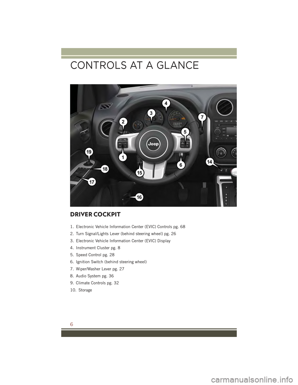
DRIVER COCKPIT
1. Electronic Vehicle Information Center (EVIC) Controls pg. 68
2. Turn Signal/Lights Lever (behind steering wheel) pg. 26
3. Electronic Vehicle Information Center (EVIC) Display
4. Instrument Cluster pg. 8
5. Speed Control pg. 28
6. Ignition Switch (behind steering wheel)
7. Wiper/Washer Lever pg. 27
8. Audio System pg. 36
9. Climate Controls pg. 32
10. Storage
CONTROLS AT A GLANCE
6
Page 11 of 132
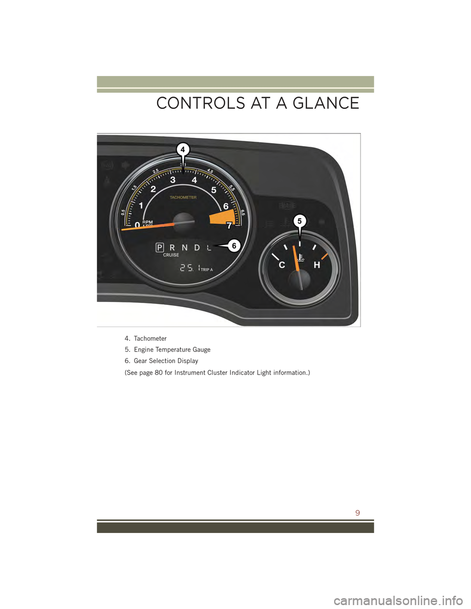
4. Tachometer
5. Engine Temperature Gauge
6. Gear Selection Display
(See page 80 for Instrument Cluster Indicator Light information.)
CONTROLS AT A GLANCE
9
Page 12 of 132
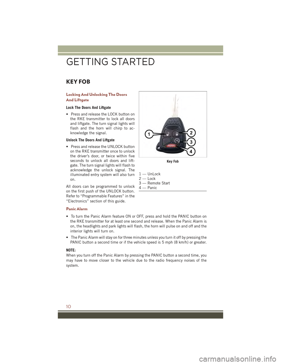
KEY FOB
Locking And Unlocking The Doors
And Liftgate
Lock The Doors And Liftgate
• Press and release the LOCK button on
the RKE transmitter to lock all doors
and liftgate. The turn signal lights will
flash and the horn will chirp to ac-
knowledge the signal.
Unlock The Doors And Liftgate
• Press and release the UNLOCK button
on the RKE transmitter once to unlock
the driver’s door, or twice within five
seconds to unlock all doors and lift-
gate. The turn signal lights will flash to
acknowledge the unlock signal. The
illuminated entry system will also turn
on.
All doors can be programmed to unlock
on the first push of the UNLOCK button.
Refer to “Programmable Features” in the
“Electronics” section of this guide.
Panic Alarm
• To turn the Panic Alarm feature ON or OFF, press and hold the PANIC button on
the RKE transmitter for at least one second and release. When the Panic Alarm is
on, the headlights and park lights will flash, the horn will pulse on and off and the
interior lights will turn on.
• The Panic Alarm will stay on for three minutes unless you turn it off by pressing the
PANIC button a second time or if the vehicle speed is 5 mph (8 km/h) or greater.
NOTE:
When you turn off the Panic Alarm by pressing the PANIC button a second time, you
may have to move closer to the vehicle due to the radio frequency noises of the
system.
Key Fob
1 — UnLock2 — Lock3 — Remote Start4 — Panic
GETTING STARTED
10
Page 14 of 132
WARNING!
• Do not start or run an engine in a closed garage or confined area. Exhaust gas
contains Carbon Monoxide (CO) which is odorless and colorless. Carbon
Monoxide is poisonous and can cause serious injury or death when inhaled.
• Keep Key Fob transmitters away from children. Operation of the Remote Start
System, windows, door locks or other controls could cause serious injury or
death.
VEHICLE SECURITY ALARM
This Vehicle Security Alarm monitors the doors, liftgate, and ignition switch for
unauthorized operation.
When the alarm is activated, the interior switches for door locks are disabled. The
Vehicle Security Alarm provides both audio and visual signals repeatedly for three
minutes. If the disturbance is still present (driver's door, passenger door, other doors,
ignition) after three minutes, the parking lights and tail lights will flash for an
additional 15 minutes.
To A r m :
• Lock the door using either the power door lock switch (one door must be open) or
the LOCK button on the Remote Keyless Entry (RKE) transmitter (doors can be
open or closed), and close all doors.
The Vehicle Security Light in the instrument cluster will flash for 16 seconds. This
shows that the Vehicle Security Alarm is arming. During this period, if a door is
opened, the ignition is cycled to ON/RUN, or the power door locks are unlocked in any
manner, the Vehicle Security Alarm will automatically disarm.
NOTE:
• The Vehicle Security Alarm will not arm if you lock the doors with the manual door
lock plungers.
• Once armed, the Vehicle Security Alarm disables the unlock switch on the driver
door trim panel and passenger door trim panel.
To D i s a r m T h e S y s t e m :
• Push the Key Fob UNLOCK button or cycle the ignition to the ON/RUN position.
The Vehicle Security Alarm is designed to protect your vehicle; however, you can
create conditions where the Vehicle Security Alarm will give you a false alarm. If one
of the previously described arming sequences has occurred, the Vehicle Security
Alarm will arm regardless of whether you are in the vehicle or not. If you remain in the
vehicle and open a door, the alarm will sound. If this occurs, disarm the Vehicle
Security Alarm.
GETTING STARTED
12
Page 15 of 132
If the Vehicle Security Alarm is armed and the battery becomes disconnected the
Vehicle Security Alarm will remain armed when the battery is reconnected. The
exterior lights will flash, and the horn will sound. If this occurs, disarm the Vehicle
Security Alarm.
SEAT BELT SYSTEMS
Lap/Shoulder Belts
• All seating positions in your vehicle are equipped with lap/shoulder belts.
• Be sure everyone in your vehicle is in a seat and using a seat belt properly.
• Position the lap belt so that it is snug and lies low across your hips, below your
abdomen. To remove slack in the lap belt portion, pull up on the shoulder belt. To
loosen the lap belt if it is too tight, tilt the latch plate and pull on the lap belt. A
snug seat belt reduces the risk of sliding under the seat belt in a collision
• Position the shoulder belt across the shoulder and chest with minimal, if any slack
so that it is comfortable and not resting on your neck. The retractor will withdraw
any slack in the shoulder belt.
Seat Belt Pretensioner
• The front seat belt system is equipped with pretensioning devices that are
designed to remove slack from the seat belt in the event of a collision.
• A deployed pretensioner or a deployed air bag must be replaced immediately.
WARNING!
• In a collision, you and your passengers can suffer much greater injuries if you
are not properly buckled up. You can strike the interior of your vehicle or other
passengers, or you can be thrown out of the vehicle. Always be sure you and
others in your vehicle are buckled up properly.
• A shoulder belt placed behind you will not protect you from injury during a
collision. You are more likely to hit your head in a collision if you do not wear
your shoulder belt. The lap and shoulder belt are meant to be used together.
• A seat belt that is too loose will not protect you properly. In a sudden stop, you
could move too far forward, increasing the possibility of injury. Wear your seat
belt snugly.
• A frayed or torn seat belt could rip apart in a collision and leave you with no
protection. Inspect the seat belt system periodically, checking for cuts, frays,
or loose parts. Damaged parts must be replaced immediately. Do not disas-
semble or modify the system. Seat belt assemblies must be replaced after a
collision.
GETTING STARTED
13
Page 16 of 132
SUPPLEMENTAL RESTRAINT SYSTEM (SRS) — AIR
BAGS
Air Bag System Components
Your vehicle may be equipped with the following air bag system components:
• Occupant Restraint Controller (ORC)
• Air Bag Warning Light
• Steering Wheel and Column
• Instrument Panel
• Knee Impact Bolsters
• Advanced Front Air Bags
• Supplemental Side Air Bags
• Front and Side Impact Sensors
• Seat Belt Pretenioners
• Seat Belt Buckle Switch
• Seat Track Position Sensors
Supplemental Side Air Bags
• This vehicle is equipped with Supplemental Seat-Mounted Side Air Bags (SABs)
located in the outboard side of the front seats. The SABs are marked with a SRS
AIRBAG label sewn into the outboard side of the seats.
• This vehicle is equipped with Supplemental Side Air Bag Inflatable Curtains
(SABICs) located above the side windows. The trim covering the SABICs is labeled
SRS AIRBAG. The SABICs may help reduce the risk of partial or complete ejection
of vehicle occupants through side windows in certain side impact events.
• The SABICs and SABs (“Side Air Bags”) are designed to activate in certain side
impacts and certain rollover events. The Occupant Restraint Controller (“ORC”)
determines whether the deployment of the Side Air Bags in a particular side
impact or rollover event is appropriate, based on the severity and type of collision.
Vehicle damage by itself is not a good indicator of whether or not Side Air Bags
should have deployed.
GETTING STARTED
14
Page 28 of 132
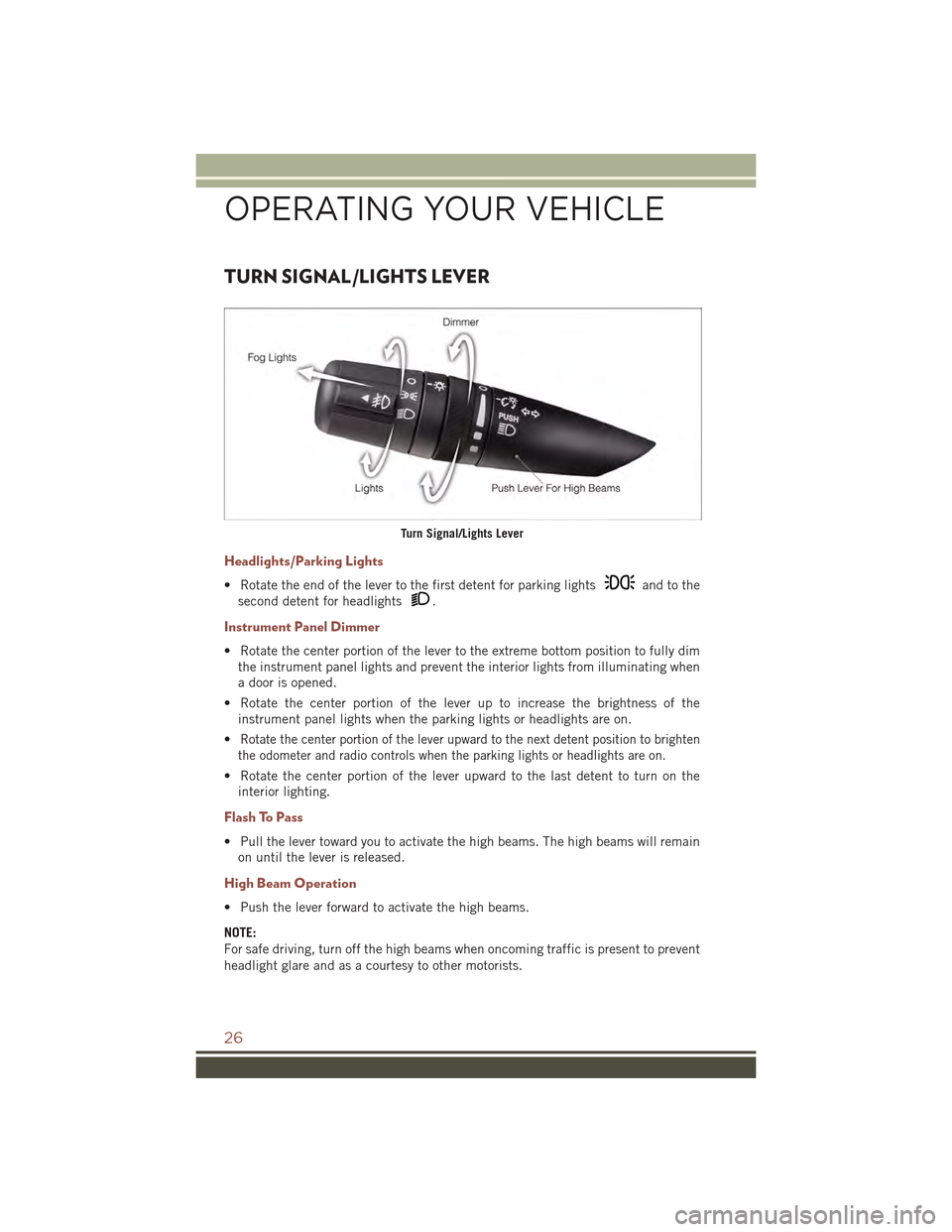
TURN SIGNAL/LIGHTS LEVER
Headlights/Parking Lights
• Rotate the end of the lever to the first detent for parking lightsand to the
second detent for headlights.
Instrument Panel Dimmer
• Rotate the center portion of the lever to the extreme bottom position to fully dim
the instrument panel lights and prevent the interior lights from illuminating when
a door is opened.
• Rotate the center portion of the lever up to increase the brightness of the
instrument panel lights when the parking lights or headlights are on.
•Rotate the center portion of the lever upward to the next detent position to brighten
the odometer and radio controls when the parking lights or headlights are on.
• Rotate the center portion of the lever upward to the last detent to turn on the
interior lighting.
Flash To Pass
• Pull the lever toward you to activate the high beams. The high beams will remain
on until the lever is released.
High Beam Operation
• Push the lever forward to activate the high beams.
NOTE:
For safe driving, turn off the high beams when oncoming traffic is present to prevent
headlight glare and as a courtesy to other motorists.
Turn Signal/Lights Lever
OPERATING YOUR VEHICLE
26
Page 29 of 132
Fog Lights
• Turn on the parking lights or low beam headlights and pull out the end of the lever.
Turn Signals/Lane Change Assist
• Tap the lever up or down once and the turn signal (right or left) will flash three
times and automatically turn off.
WIPER/WASHER LEVER
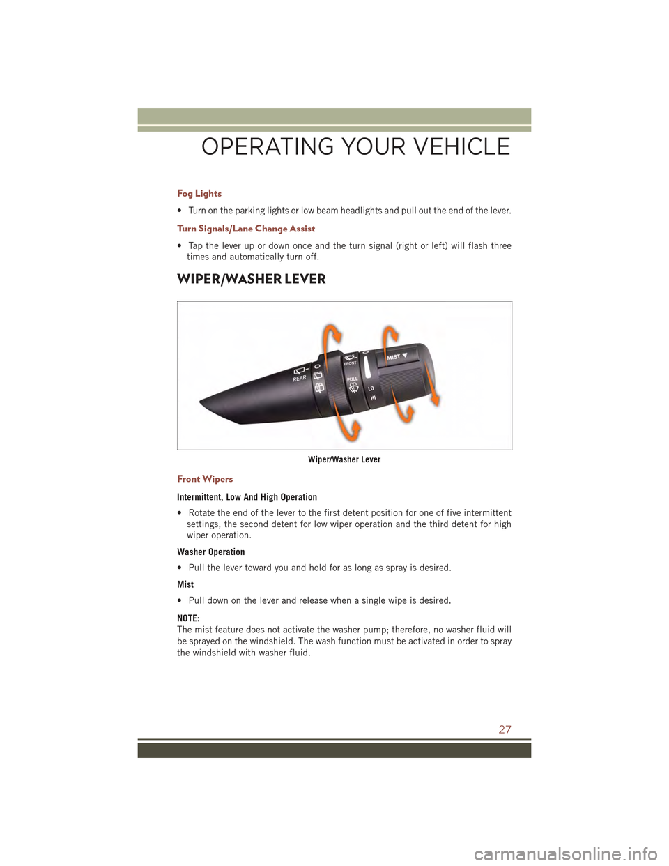
Front Wipers
Intermittent, Low And High Operation
• Rotate the end of the lever to the first detent position for one of five intermittent
settings, the second detent for low wiper operation and the third detent for high
wiper operation.
Washer Operation
• Pull the lever toward you and hold for as long as spray is desired.
Mist
• Pull down on the lever and release when a single wipe is desired.
NOTE:
The mist feature does not activate the washer pump; therefore, no washer fluid will
be sprayed on the windshield. The wash function must be activated in order to spray
the windshield with washer fluid.
Wiper/Washer Lever
OPERATING YOUR VEHICLE
27
Page 35 of 132
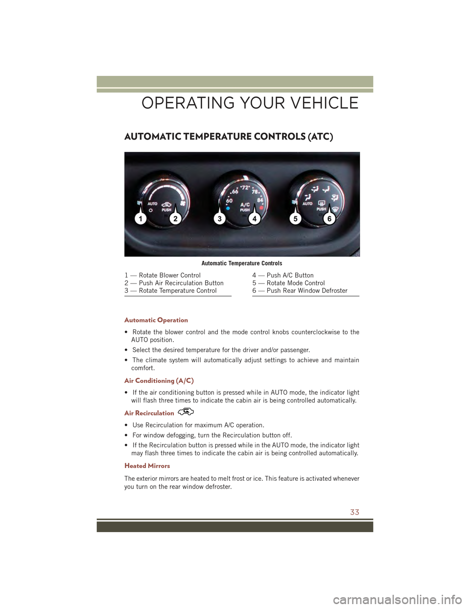
AUTOMATIC TEMPERATURE CONTROLS (ATC)
Automatic Operation
• Rotate the blower control and the mode control knobs counterclockwise to the
AUTO position.
• Select the desired temperature for the driver and/or passenger.
• The climate system will automatically adjust settings to achieve and maintain
comfort.
Air Conditioning (A/C)
• If the air conditioning button is pressed while in AUTO mode, the indicator light
will flash three times to indicate the cabin air is being controlled automatically.
Air Recirculation
• Use Recirculation for maximum A/C operation.
• For window defogging, turn the Recirculation button off.
• If the Recirculation button is pressed while in the AUTO mode, the indicator light
may flash three times to indicate the cabin air is being controlled automatically.
Heated Mirrors
The exterior mirrors are heated to melt frost or ice. This feature is activated whenever
you turn on the rear window defroster.
Automatic Temperature Controls
1 — Rotate Blower Control2 — Push Air Recirculation Button3 — Rotate Temperature Control
4 — Push A/C Button5 — Rotate Mode Control6 — Push Rear Window Defroster
OPERATING YOUR VEHICLE
33