warning light JEEP COMPASS 2016 1.G Owner's Manual
[x] Cancel search | Manufacturer: JEEP, Model Year: 2016, Model line: COMPASS, Model: JEEP COMPASS 2016 1.GPages: 148, PDF Size: 8.42 MB
Page 89 of 148
ROADSIDE ASSISTANCE
Dial toll-free 1-800-521-2779 for U.S. Residents or 1-800-363-4869 for Canadian
Residents.
• Provide your name, vehicle identification number, license plate number, and yourlocation, including the telephone number from which you are calling.
• Briefly describe the nature of the problem and answer a few simple questions.
• You will be given the name of the service provider and an estimated time of arrival. If you feel you are in an “unsafe situation”, please let us know. With your consent,
we will contact local police or safety authorities.
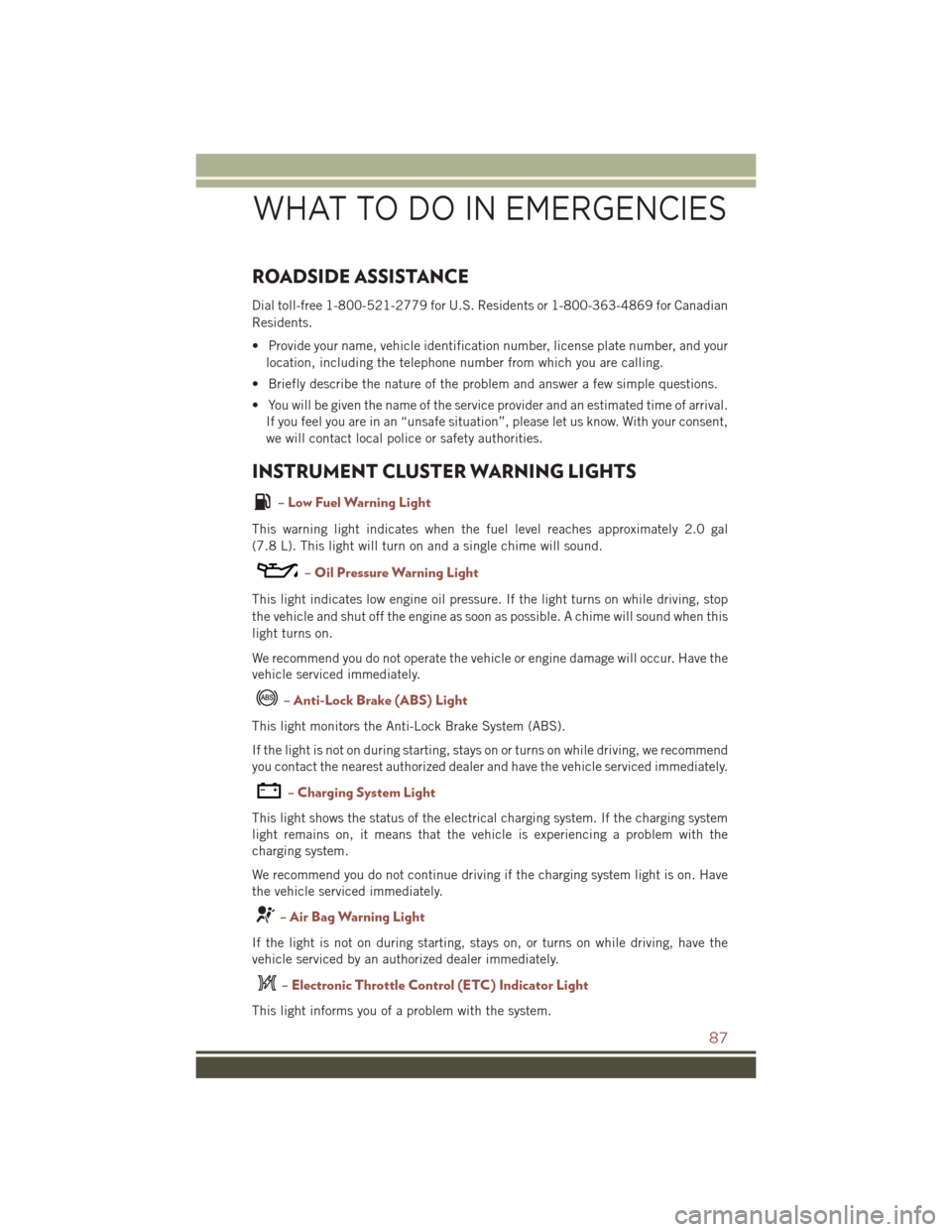
INSTRUMENT CLUSTER WARNING LIGHTS
– Low Fuel Warning Light
This warning light indicates when the fuel level reaches approximately 2.0 gal
(7.8 L). This light will turn on and a single chime will sound.
– Oil Pressure Warning Light
This light indicates low engine oil pressure. If the light turns on while driving, stop
the vehicle and shut off the engine as soon as possible. A chime will sound when this
light turns on.
We recommend you do not operate the vehicle or engine damage will occur. Have the
vehicle serviced immediately.
– Anti-Lock Brake (ABS) Light
This light monitors the Anti-Lock Brake System (ABS).
If the light is not on during starting, stays on or turns on while driving, we recommend
you contact the nearest authorized dealer and have the vehicle serviced immediately.
– Charging System Light
This light shows the status of the electrical charging system. If the charging system
light remains on, it means that the vehicle is experiencing a problem with the
charging system.
We recommend you do not continue driving if the charging system light is on. Have
the vehicle serviced immediately.
– Air Bag Warning Light
If the light is not on during starting, stays on, or turns on while driving, have the
vehicle serviced by an authorized dealer immediately.
– Electronic Throttle Control (ETC) Indicator Light
This light informs you of a problem with the system.
WHAT TO DO IN EMERGENCIES
87
Page 91 of 148
NOTE:
Tire pressures change by approximately 1 psi (7 kPa) per 12° F (7° C) of air
temperature change. Keep this in mind when checking tire pressure inside a garage,
especially in the Winter. Example: If garage temperature is 68°F (20°C), and the
outside temperature is 32°F (0°C), then the cold tire inflation pressure should be
increased by 3 psi (21 kPa), which equals 1 psi (7 kPa) for every 12°F (7°C) for this
outside temperature condition.
CAUTION!
The TPMS has been optimized for the original equipment tires and wheels. TPMS
pressures and warning have been established for the tire size equipped on your
vehicle. Undesirable system operation or sensor damage may result when using
replacement equipment that is not of the same size, type, and/or style. Aftermar-
ket wheels can cause sensor damage. Do not use tire sealant from a can, or
balance beads if your vehicle is equipped with a TPMS, as damage to the sensors
may result.
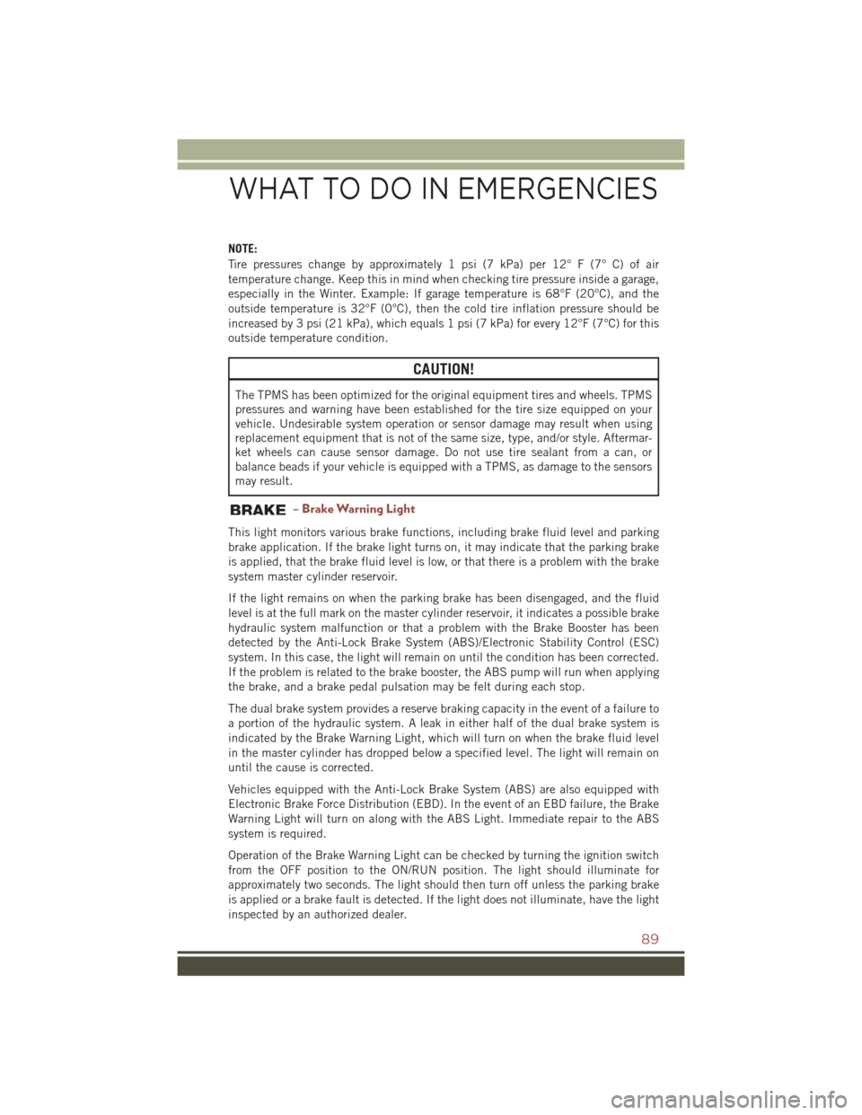
– Brake Warning Light
This light monitors various brake functions, including brake fluid level and parking
brake application. If the brake light turns on, it may indicate that the parking brake
is applied, that the brake fluid level is low, or that there is a problem with the brake
system master cylinder reservoir.
If the light remains on when the parking brake has been disengaged, and the fluid
level is at the full mark on the master cylinder reservoir, it indicates a possible brake
hydraulic system malfunction or that a problem with the Brake Booster has been
detected by the Anti-Lock Brake System (ABS)/Electronic Stability Control (ESC)
system. In this case, the light will remain on until the condition has been corrected.
If the problem is related to the brake booster, the ABS pump will run when applying
the brake, and a brake pedal pulsation may be felt during each stop.
The dual brake system provides a reserve braking capacity in the event of a failure to
a portion of the hydraulic system. A leak in either half of the dual brake system is
indicated by the Brake Warning Light, which will turn on when the brake fluid level
in the master cylinder has dropped below a specified level. The light will remain on
until the cause is corrected.
Vehicles equipped with the Anti-Lock Brake System (ABS) are also equipped with
Electronic Brake Force Distribution (EBD). In the event of an EBD failure, the Brake
Warning Light will turn on along with the ABS Light. Immediate repair to the ABS
system is required.
Operation of the Brake Warning Light can be checked by turning the ignition switch
from the OFF position to the ON/RUN position. The light should illuminate for
approximately two seconds. The light should then turn off unless the parking brake
is applied or a brake fault is detected. If the light does not illuminate, have the light
inspected by an authorized dealer.
WHAT TO DO IN EMERGENCIES
89
Page 92 of 148
The light also will turn on when the parking brake is applied with the ignition switch
in the ON/RUN position.
NOTE:
This light shows only that the parking brake is applied. It does not show the degree
of brake application.
WARNING!
Driving a vehicle with the red brake light on is dangerous. Part of the brake system
may have failed. It will take longer to stop the vehicle. You could have a collision.
Have the vehicle checked immediately.
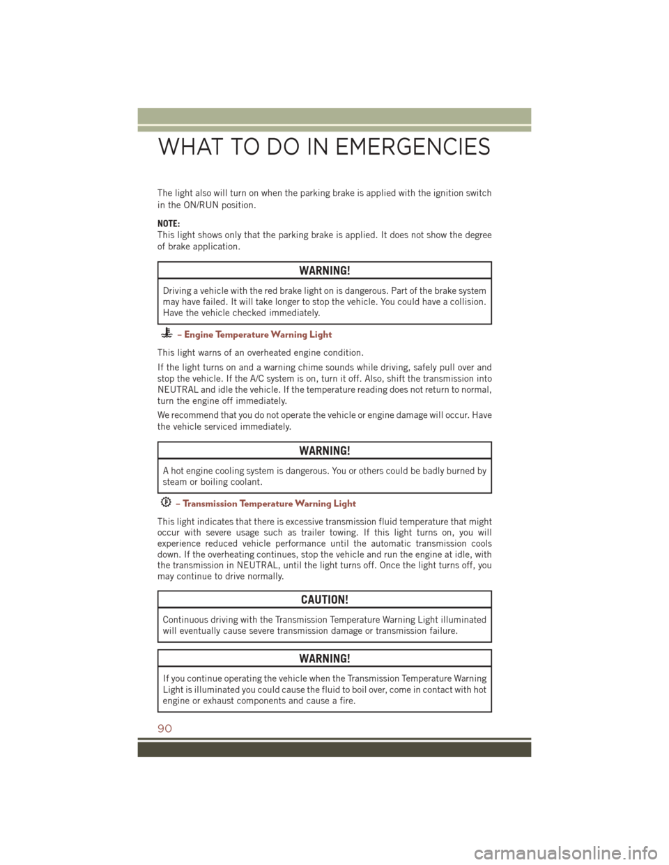
– Engine Temperature Warning Light
This light warns of an overheated engine condition.
If the light turns on and a warning chime sounds while driving, safely pull over and
stop the vehicle. If the A/C system is on, turn it off. Also, shift the transmission into
NEUTRAL and idle the vehicle. If the temperature reading does not return to normal,
turn the engine off immediately.
We recommend that you do not operate the vehicle or engine damage will occur. Have
the vehicle serviced immediately.
WARNING!
A hot engine cooling system is dangerous. You or others could be badly burned by
steam or boiling coolant.
– Transmission Temperature Warning Light
This light indicates that there is excessive transmission fluid temperature that might
occur with severe usage such as trailer towing. If this light turns on, you will
experience reduced vehicle performance until the automatic transmission cools
down. If the overheating continues, stop the vehicle and run the engine at idle, with
the transmission in NEUTRAL, until the light turns off. Once the light turns off, you
may continue to drive normally.
CAUTION!
Continuous driving with the Transmission Temperature Warning Light illuminated
will eventually cause severe transmission damage or transmission failure.
WARNING!
If you continue operating the vehicle when the Transmission Temperature Warning
Light is illuminated you could cause the fluid to boil over, come in contact with hot
engine or exhaust components and cause a fire.
WHAT TO DO IN EMERGENCIES
90
Page 95 of 148
IF YOUR ENGINE OVERHEATS
In any of the following situations, you can reduce the potential for overheating by
taking the appropriate action:
• On the highways — slow down.
• In city traffic — while stopped, shift the transmission to NEUTRAL, but do notincrease engine idle speed.
NOTE:
There are steps that you can take to slow down an impending overheat condition:
• If your air conditioner (A/C) is on, turn it off. The A/C system adds heat to the engine cooling system and turning the A/C off can help remove this heat.
• You can also turn the temperature control to maximum heat, the mode control to floor and the blower control to high. This allows the heater core to act as a
supplement to the radiator and aids in removing heat from the engine cooling
system.
CAUTION!
Driving with a hot cooling system could damage your vehicle. If the temperature
gauge reads HOT (H), pull over and stop the vehicle. Idle the vehicle with the air
conditioner turned off until the pointer drops back into the normal range. If the
pointer remains on HOT (H), and you hear continuous chimes, turn the engine off
immediately, and call for service.
WARNING!
You or others can be badly burned by hot engine coolant (antifreeze) or steam from
your radiator. If you see or hear steam coming from under the hood, do not open
the hood until the radiator has had time to cool. Never try to open a cooling system
pressure cap when the radiator or coolant bottle is hot.
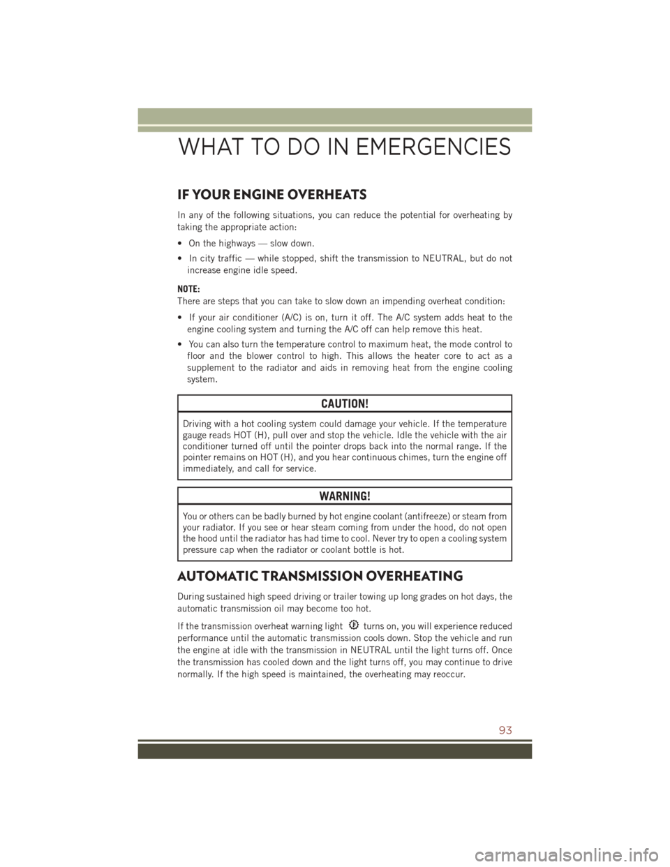
AUTOMATIC TRANSMISSION OVERHEATING
During sustained high speed driving or trailer towing up long grades on hot days, the
automatic transmission oil may become too hot.
If the transmission overheat warning light
turns on, you will experience reduced
performance until the automatic transmission cools down. Stop the vehicle and run
the engine at idle with the transmission in NEUTRAL until the light turns off. Once
the transmission has cooled down and the light turns off, you may continue to drive
normally. If the high speed is maintained, the overheating may reoccur.
WHAT TO DO IN EMERGENCIES
93
Page 101 of 148
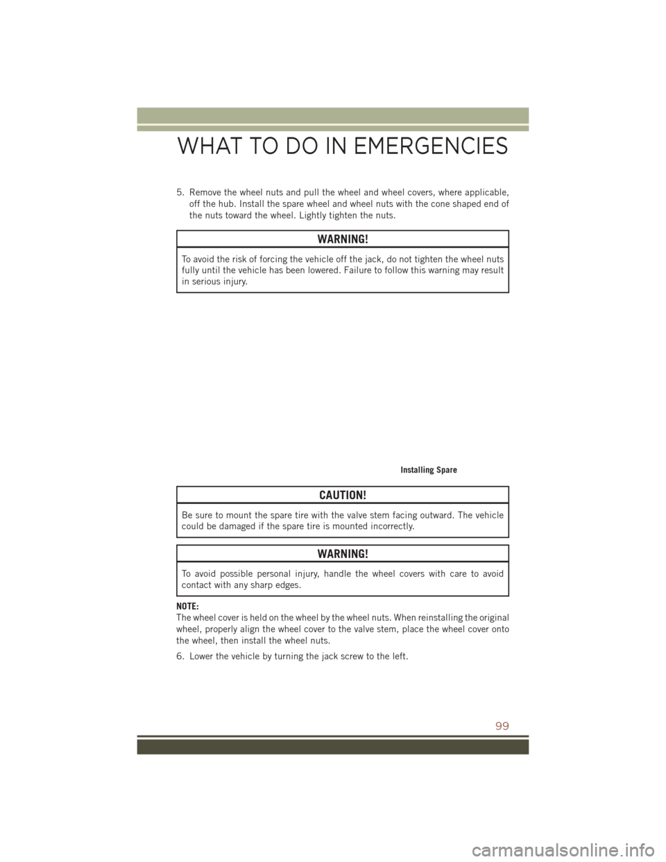
5. Remove the wheel nuts and pull the wheel and wheel covers, where applicable,off the hub. Install the spare wheel and wheel nuts with the cone shaped end of
the nuts toward the wheel. Lightly tighten the nuts.
WARNING!
To avoid the risk of forcing the vehicle off the jack, do not tighten the wheel nuts
fully until the vehicle has been lowered. Failure to follow this warning may result
in serious injury.
CAUTION!
Be sure to mount the spare tire with the valve stem facing outward. The vehicle
could be damaged if the spare tire is mounted incorrectly.
WARNING!
To avoid possible personal injury, handle the wheel covers with care to avoid
contact with any sharp edges.
NOTE:
The wheel cover is held on the wheel by the wheel nuts. When reinstalling the original
wheel, properly align the wheel cover to the valve stem, place the wheel cover onto
the wheel, then install the wheel nuts.
6. Lower the vehicle by turning the jack screw to the left.
Installing Spare
WHAT TO DO IN EMERGENCIES
99
Page 103 of 148
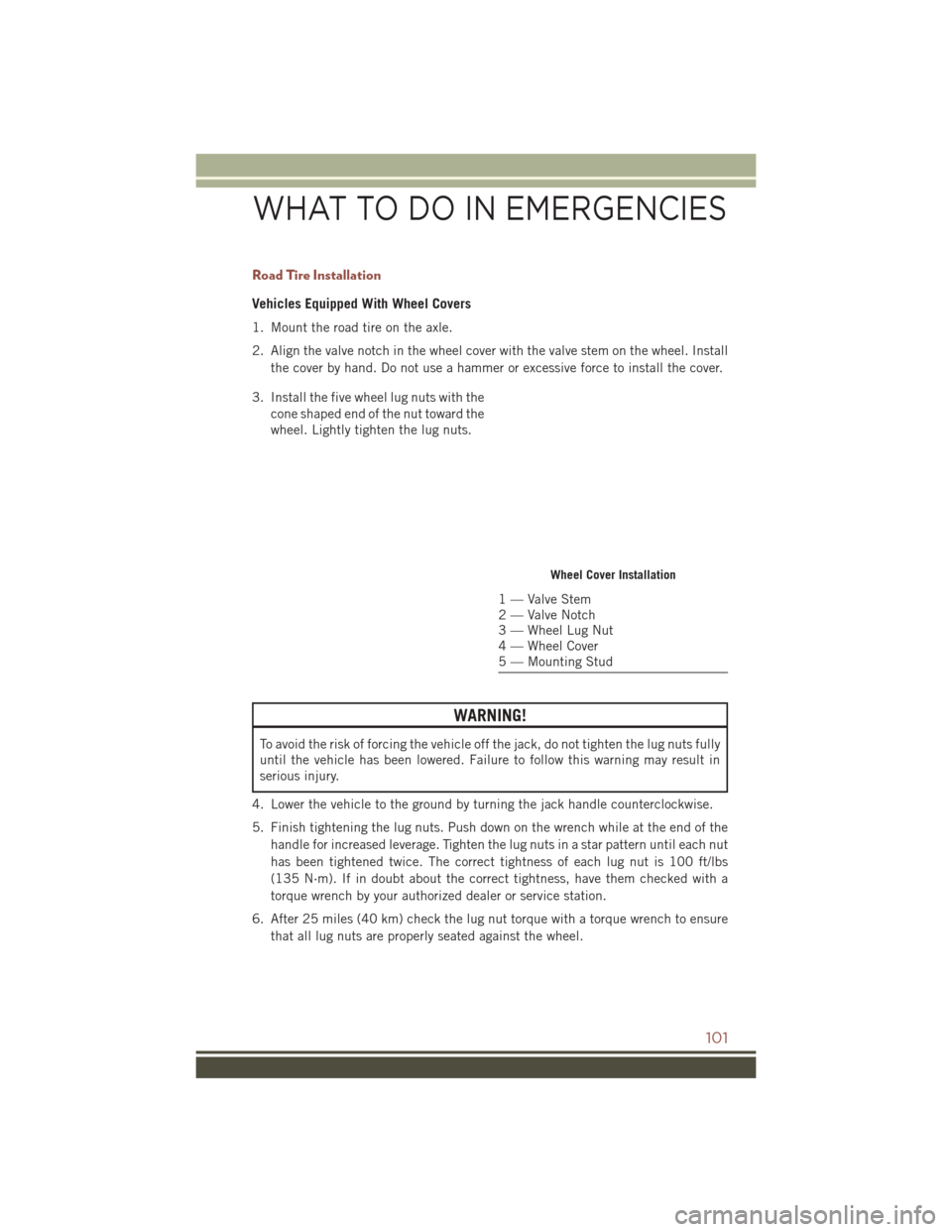
Road Tire Installation
Vehicles Equipped With Wheel Covers
1. Mount the road tire on the axle.
2. Align the valve notch in the wheel cover with the valve stem on the wheel. Installthe cover by hand. Do not use a hammer or excessive force to install the cover.
3. Install the five wheel lug nuts with the cone shaped end of the nut toward the
wheel. Lightly tighten the lug nuts.
WARNING!
To avoid the risk of forcing the vehicle off the jack, do not tighten the lug nuts fully
until the vehicle has been lowered. Failure to follow this warning may result in
serious injury.
4. Lower the vehicle to the ground by turning the jack handle counterclockwise.
5. Finish tightening the lug nuts. Push down on the wrench while at the end of the handle for increased leverage. Tighten the lug nuts in a star pattern until each nut
has been tightened twice. The correct tightness of each lug nut is 100 ft/lbs
(135 N·m). If in doubt about the correct tightness, have them checked with a
torque wrench by your authorized dealer or service station.
6. After 25 miles (40 km) check the lug nut torque with a torque wrench to ensure that all lug nuts are properly seated against the wheel.
Wheel Cover Installation
1 — Valve Stem
2 — Valve Notch
3 — Wheel Lug Nut
4 — Wheel Cover
5 — Mounting Stud
WHAT TO DO IN EMERGENCIES
101
Page 104 of 148
Vehicles Without Wheel Covers
1. Mount the road tire on the axle.
2. Install the remaining lug nuts with the cone shaped end of the nut toward thewheel. Lightly tighten the lug nuts.
WARNING!
To avoid the risk of forcing the vehicle off the jack, do not fully tighten the lug nuts
until the vehicle has been lowered. Failure to follow this warning may result in
serious injury.
3. Lower the vehicle to the ground by turning the jack handle counterclockwise.
4. Finish tightening the lug nuts. Push down on the wrench while at the end of the handle for increased leverage. Tighten the lug nuts in a star pattern until each nut
has been tightened twice. The correct tightness of each lug nut is 100 ft/lbs
(135 N·m). If in doubt about the correct tightness, have them checked with a
torque wrench by your authorized dealer or service station.
5. After 25 miles (40 km) check the lug nut torque with a torque wrench to ensure that all lug nuts are properly seated against the wheel.
JUMP-STARTING PROCEDURES
If your vehicle has a discharged battery it can be jump-started using a set of jumper
cables and a battery in another vehicle or by using a portable battery booster pack.
Jump-starting can be dangerous if done improperly so please follow the procedures
in this section carefully.
NOTE:
When using a portable battery booster pack follow the manufacturer’s operating
instructions and precautions.
CAUTION!
Do not use a portable battery booster pack or any other booster source with a
system voltage greater than 12 Volts or damage to the battery, starter motor,
alternator or electrical system may occur.
WARNING!
Do not attempt jump-starting if the battery is frozen. It could rupture or explode
and cause personal injury.
WHAT TO DO IN EMERGENCIES
102
Page 118 of 148
MAINTENANCE PROCEDURES
For information on the maintenance procedures for your vehicle, please refer to
“Maintenance Procedures” in “Maintaining Your Vehicle” in your Owner’s Manual or
applicable supplement on the DVD for further details.
MAINTENANCE SCHEDULE
Your vehicle is equipped with an automatic oil change indicator system. The oil
change indicator system will remind you that it is time to take your vehicle in for
scheduled maintenance.
Based on engine operation conditions, the oil change indicator message will
illuminate. This means that service is required for your vehicle. Operating conditions
such as frequent short-trips, trailer tow, extremely hot or cold ambient temperatures
will influence when the “Change Oil” or “Oil Change Required” message is dis-
played. Severe Operating Conditions can cause the change oil message to illuminate
as early as 3,500 miles (5,600 km) since last reset. Have your vehicle serviced as
soon as possible, within the next 500 miles (805 km).
On Electronic Vehicle Information Center (EVIC) equipped vehicles, “Oil Change
Required” will be displayed in the EVIC and a single chime will sound, indicating that
an oil change is necessary.
On Non-EVIC equipped vehicles, “Change Oil” will flash in the instrument cluster
odometer and a single chime will sound, indicating that an oil change is necessary.
Your authorized dealer will reset the oil change indicator message after completing
the scheduled oil change. If a scheduled oil change is performed by someone other
than your authorized dealer, the message can be reset by referring to the steps
described under “Instrument Cluster Warning Lights” in “What To Do In Emergen-
cies” in this guide or “Instrument Cluster Descriptions” or “Electronic Vehicle
Information Center (EVIC)” in “Understanding Your Instrument Panel” in the
Owner’s Manual on your DVD for further information.
NOTE:
Under no circumstances should oil change intervals exceed 10,000 miles
(16,000 km), twelve months or 350 hours of engine run time, whichever comes first.
The 350 hours of engine run or idle time is generally only a concern for fleet
customers.
Severe Duty All Models
Change Engine Oil at 4,000 miles (6,500 km) if the vehicle is operated in a dusty
and off road environment or is operated predominately at idle or only very low engine
RPM’s. This type of vehicle use is considered Severe Duty.
MAINTAINING YOUR VEHICLE
116
Page 123 of 148
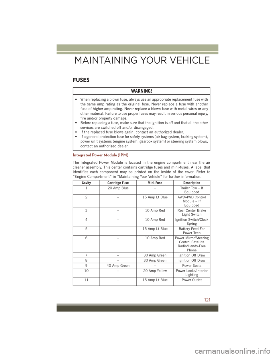
FUSES
WARNING!
• When replacing a blown fuse, always use an appropriate replacement fuse withthe same amp rating as the original fuse. Never replace a fuse with another
fuse of higher amp rating. Never replace a blown fuse with metal wires or any
other material. Failure to use proper fuses may result in serious personal injury,
fire and/or property damage.
• Before replacing a fuse, make sure that the ignition is off and that all the other
services are switched off and/or disengaged.
• If the replaced fuse blows again, contact an authorized dealer.
• If a general protection fuse for safety systems (air bag system, braking system),
power unit systems (engine system, gearbox system) or steering system blows,
contact an authorized dealer.
Integrated Power Module (IPM)
The Integrated Power Module is located in the engine compartment near the air
cleaner assembly. This center contains cartridge fuses and mini-fuses. A label that
identifies each component may be printed on the inside of the cover. Refer to
“Engine Compartment” in “Maintaining Your Vehicle” for further information.
Cavity Cartridge Fuse Mini-FuseDescription
1 20 Amp Blue –Trailer Tow – If
Equipped
2 –15 Amp Lt Blue AWD/4WD Control
Module – IfEquipped
3 –10 Amp Red Rear Center Brake
Light Switch
4 –10 Amp Red Ignition Switch/Clock
Spring
5 –15 Amp Lt Blue Battery Feed For
Power Tech
6 –10 Amp Red Power Mirror/Steering
Control Satellite
Radio/Hands-Free Phone
7 –30 Amp Green Ignition Off Draw
8 –30 Amp Green Ignition Off Draw
9 40 Amp Green –Power Seats
10 –20 Amp Yellow Power Locks/Interior
Lighting
11 –15 Amp Lt Blue Power Outlet
MAINTAINING YOUR VEHICLE
121
Page 132 of 148
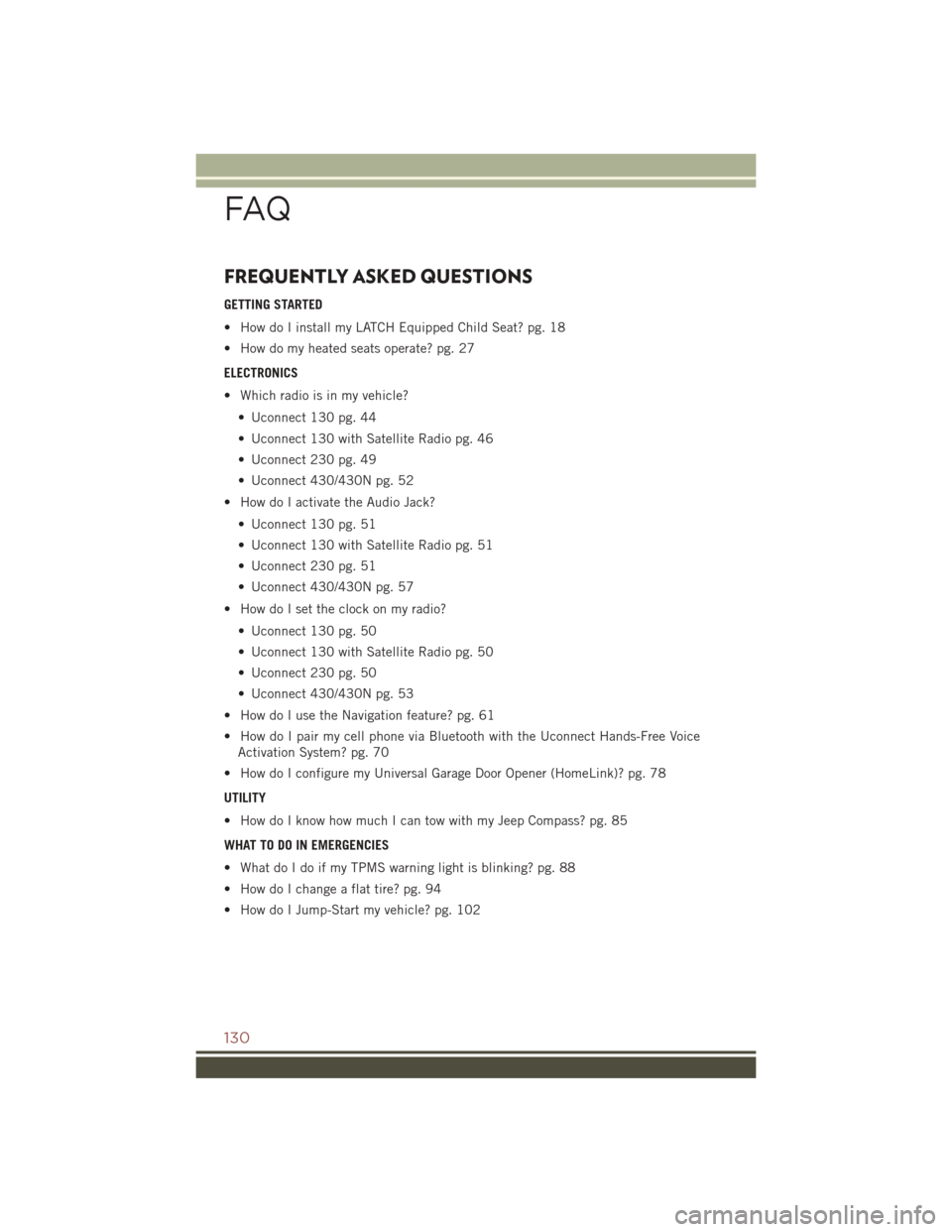
FREQUENTLY ASKED QUESTIONS
GETTING STARTED
• How do I install my LATCH Equipped Child Seat? pg. 18
• How do my heated seats operate? pg. 27
ELECTRONICS
• Which radio is in my vehicle?• Uconnect 130 pg. 44
• Uconnect 130 with Satellite Radio pg. 46
• Uconnect 230 pg. 49
• Uconnect 430/430N pg. 52
• How do I activate the Audio Jack?
• Uconnect 130 pg. 51
• Uconnect 130 with Satellite Radio pg. 51
• Uconnect 230 pg. 51
• Uconnect 430/430N pg. 57
• How do I set the clock on my radio?
• Uconnect 130 pg. 50
• Uconnect 130 with Satellite Radio pg. 50
• Uconnect 230 pg. 50
• Uconnect 430/430N pg. 53
• How do I use the Navigation feature? pg. 61
• How do I pair my cell phone via Bluetooth with the Uconnect Hands-Free Voice Activation System? pg. 70
• How do I configure my Universal Garage Door Opener (HomeLink)? pg. 78
UTILITY
• How do I know how much I can tow with my Jeep Compass? pg. 85
WHAT TO DO IN EMERGENCIES
• What do I do if my TPMS warning light is blinking? pg. 88
• How do I change a flat tire? pg. 94
• How do I Jump-Start my vehicle? pg. 102
FAQ
130