warning light JEEP COMPASS 2016 1.G User Guide
[x] Cancel search | Manufacturer: JEEP, Model Year: 2016, Model line: COMPASS, Model: JEEP COMPASS 2016 1.GPages: 148, PDF Size: 8.42 MB
Page 3 of 148
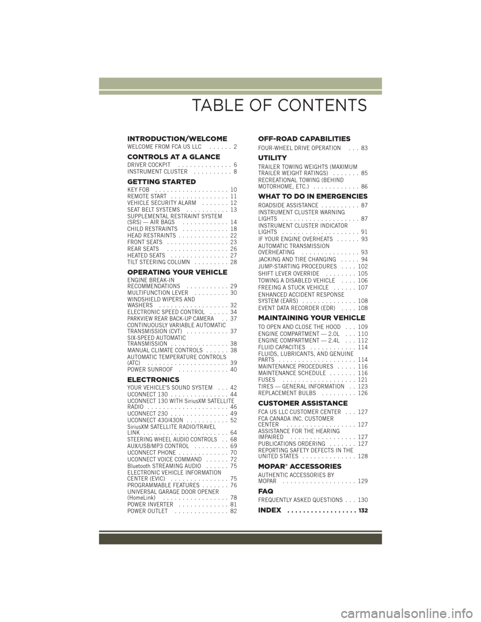
INTRODUCTION/WELCOMEWELCOME FROM FCA US LLC...... 2
CONTROLS AT A GLANCEDRIVER COCKPIT.............. 6
INSTRUMENT CLUSTER .......... 8
GETTING STARTEDKEYFOB ................... 10
REMOTE START............... 11
VEHICLE SECURITY ALARM ....... 12
SEAT BELT SYSTEMS ........... 13
SUPPLEMENTAL RESTRAINT SYSTEM
(SRS) — AIR BAGS ............ 14
CHILD RESTRAINTS ............ 18
HEAD RESTRAINTS ............. 22
FRONT SEATS ................ 23
REAR SEATS ................ 26
HEATEDSEATS ............... 27
TILT STEERING COLUMN ......... 28
OPERATING YOUR VEHICLEENGINE BREAK-IN
RECOMMENDATIONS........... 29
MULTIFUNCTION LEVER ......... 30
WINDSHIELD WIPERS AND
WASHERS .................. 32
ELECTRONIC SPEED CONTROL ..... 34
PARKVIEW REAR BACK-UP CAMERA.. 37
CONTINUOUSLY VARIABLE AUTOMATIC
TRANSMISSION (CVT) ........... 37
SIX-SPEED AUTOMATIC
TRANSMISSION ............... 38
MANUAL CLIMATE CONTROLS ...... 38
AUTOMATIC TEMPERATURE CONTROLS
(ATC) ..................... 39
POWER SUNROOF ............. 40
ELECTRONICSYOUR VEHICLE'S SOUND SYSTEM . . . 42
UCONNECT 130............... 44
UCONNECT 130 WITH SiriusXM SATELLITE
RADIO ..................... 46
UCONNECT 230 ............... 49
UCONNECT 430/430N ........... 52
SiriusXM SATELLITE RADIO/TRAVEL
LINK ...................... 64
STEERING WHEEL AUDIO CONTROLS.. 68
AUX/USB/MP3 CONTROL ......... 69
UCONNECT PHONE ............. 70
UCONNECT VOICE COMMAND ...... 72
Bluetooth STREAMING AUDIO ...... 75
ELECTRONIC VEHICLE INFORMATION
CENTER (EVIC) ............... 75
PROGRAMMABLE FEATURES ....... 76
UNIVERSAL GARAGE DOOR OPENER
(HomeLink) ................. 78
POWER INVERTER ............. 81
POWER OUTLET .............. 82
OFF-ROAD CAPABILITIES
FOUR-WHEEL DRIVE OPERATION . . . 83
UTILITY
TRAILER TOWING WEIGHTS (MAXIMUM
TRAILER WEIGHT RATINGS) ....... 85
RECREATIONAL TOWING (BEHIND
MOTORHOME, ETC.) ............ 86
WHAT TO DO IN EMERGENCIES
ROADSIDE ASSISTANCE .......... 87
INSTRUMENT CLUSTER WARNING
LIGHTS .................... 87
INSTRUMENT CLUSTER INDICATOR
LIGHTS .................... 91
IF YOUR ENGINE OVERHEATS ...... 93
AUTOMATIC TRANSMISSION
OVERHEATING ............... 93
JACKING AND TIRE CHANGING ..... 94
JUMP-STARTING PROCEDURES .... 102
SHIFT LEVER OVERRIDE ........ 105
TOWING A DISABLED VEHICLE .... 106
FREEING A STUCK VEHICLE ...... 107
ENHANCED ACCIDENT RESPONSE
SYSTEM (EARS) .............. 108
EVENT DATA RECORDER (EDR) .... 108
MAINTAINING YOUR VEHICLE
TO OPEN AND CLOSE THE HOOD . . . 109
ENGINE COMPARTMENT — 2.0L . . . 110
ENGINE COMPARTMENT — 2.4L . . . 112
FLUID CAPACITIES............ 114
FLUIDS, LUBRICANTS, AND GENUINE
PARTS .................... 114
MAINTENANCE PROCEDURES ..... 116
MAINTENANCE SCHEDULE ....... 116
FUSES ................... 121
TIRES — GENERAL INFORMATION . . 123
REPLACEMENT BULBS ......... 126
CUSTOMER ASSISTANCE
FCA US LLC CUSTOMER CENTER . . . 127
FCA CANADA INC. CUSTOMER
CENTER.................. 127
ASSISTANCE FOR THE HEARING
IMPAIRED ................. 127
PUBLICATIONS ORDERING ....... 127
REPORTING SAFETY DEFECTS IN THE
UNITEDSTATES .............. 128
MOPAR® ACCESSORIES
AUTHENTIC ACCESSORIES BY
MOPAR ................... 129
FAQ
FREQUENTLY ASKED QUESTIONS . . . 130
INDEX.................. 132
TABLE OF CONTENTS
Page 10 of 148
INSTRUMENT CLUSTER
1. Fuel Gauge
2. Speedometer
(See page 87 for Instrument Cluster Warning Light information.)
CONTROLS AT A GLANCE
8
Page 14 of 148
WARNING!
• Do not start or run an engine in a closed garage or confined area. Exhaust gascontains Carbon Monoxide (CO) which is odorless and colorless. Carbon
Monoxide is poisonous and can cause serious injury or death when inhaled.
•
Keep Key Fob transmitters away from children. Operation of the Remote Start
System, windows, door locks or other controls could cause serious injury or death.
VEHICLE SECURITY ALARM
The Vehicle Security Alarm monitors the vehicle doors for unauthorized entry and the
ignition for unauthorized operation. While the Vehicle Security Alarm is armed,
interior switches for door locks and decklid release are disabled. If something triggers
the alarm, the Vehicle Security Alarm will provide the following audible and visible
signals: the horn will pulse, the park lamps and/or turn signals will flash, and the
Vehicle Security Light in the instrument cluster will flash.
To Arm The System:
Lock the door using either the power door lock switch (one door must be open) or the
LOCK button on the Remote Keyless Entry (RKE) transmitter (doors can be open or
closed), and close all doors.
The Vehicle Security Light in the instrument cluster will flash for 16 seconds. This
shows that the Vehicle Security Alarm is arming. During this period, if a door is
opened, the ignition is cycled to ON/RUN, or the power door locks are unlocked in any
manner, the Vehicle Security Alarm will automatically disarm.
NOTE:
• The Vehicle Security Alarm will not arm if you lock the doors with the manual door lock plungers.
• Once armed, the Vehicle Security Alarm disables the unlock switch on the driver door trim panel and passenger door trim panel.
To Disarm The System:
Push the Key Fob UNLOCK button or cycle the ignition to the ON/RUN position.
The Vehicle Security Alarm is designed to protect your vehicle. However, you can
create conditions where the Vehicle Security Alarm will give you a false alarm. If one
of the previously described arming sequences has occurred, the Vehicle Security
Alarm will arm regardless of whether you are in the vehicle or not. If you remain in the
vehicle and open a door, the alarm will sound. If this occurs, disarm the Vehicle
Security Alarm.
If the Vehicle Security Alarm is armed and the battery becomes disconnected, the
Vehicle Security Alarm will remain armed when the battery is reconnected. The
exterior lights will flash, and the horn will sound. If this occurs, disarm the Vehicle
Security Alarm.
GETTING STARTED
12
Page 16 of 148
SUPPLEMENTAL RESTRAINT SYSTEM (SRS) — AIR
BAGS
Air Bag System Components
Your vehicle may be equipped with the following air bag system components:
• Occupant Restraint Controller (ORC)
• Air Bag Warning Light
• Steering Wheel and Column
• Instrument Panel
• Knee Impact Bolsters
• Advanced Front Air Bags
• Supplemental Side Air Bags
• Front and Side Impact Sensors
• Seat Belt Pretensioners
• Seat Belt Buckle Switch
• Seat Track Position Sensors
Advanced Front Air Bags
• This vehicle has Advanced Front Air Bags for both the driver and front passengeras a supplement to the seat belt restraint systems. The Advanced Front Air Bags
will not deploy in every type of collision.
• Advanced Front Air Bags are designed to provide additional protection by supplementing the seat belts. Advanced Front Air Bags are not expected to reduce
the risk of injury in rear, side, or rollover collisions.
• The Advanced Front Air Bags will not deploy in all frontal collisions, including some that may produce substantial vehicle damage — for example, some pole
collisions, truck underrides, and angle offset collisions.
• On the other hand, depending on the type and location of impact, Advanced Front Air Bags may deploy in crashes with little vehicle front-end damage but that
produce a severe initial deceleration.
• Because air bag sensors measure vehicle deceleration over time, vehicle speed and damage by themselves are not good indicators of whether or not an air bag
should have deployed.
• Seat belts are necessary for your protection in all collisions, and also are needed to help keep you in position, away from an inflating air bag.
• After any collision, the vehicle should be taken to an authorized dealer immedi- ately.
• Do not drive your vehicle after the air bags have deployed. If you are involved in another collision, the air bags will not be in place to protect you.
GETTING STARTED
14
Page 18 of 148
WARNING!
• Side Air Bags need room to inflate. Do not lean against the door or window. Situpright in the center of the seat.
• Being too close to the Side Air Bags during deployment could cause you to be
severely injured or killed.
• Relying on the Side Air Bags alone could lead to more severe injuries in a
collision. The Side Air Bags work with your seat belt to restrain you properly. In
some collisions, Side Air Bags won’t deploy at all. Always wear your seat belt
even though you have Side Air Bags.
• This vehicle is equipped with left and right Supplemental Side Air Bag
Inflatable Curtains (SABICs). Do not stack luggage or other cargo up high
enough to block the deployment of the SABICs. The trim covering above the
side windows where the SABIC and its deployment path are located should
remain free from any obstructions.
• This vehicle is equipped with SABICs. In order for the SABICs to work as
intended, do not install any accessory items in your vehicle which could alter
the roof. Do not add an aftermarket sunroof to your vehicle. Do not add roof
racks that require permanent attachments (bolts or screws) for installation on
the vehicle roof. Do not drill into the roof of the vehicle for any reason.
• Do not use accessory seat covers or place objects between you and the Side Air
Bags; the performance could be adversely affected and/or objects could be
pushed into you, causing serious injury.
Enhanced Accident Response System
In the event of an impact, if the communication network remains intact, and the
power remains intact, depending on the nature of the event, the ORC will determine
whether to have the Enhanced Accident Response System perform the following
functions:
• Cut off fuel to the engine.
• Flash hazard lights as long as the battery has power or until the hazard light button
is pushed. The hazard lights can be deactivated by pushing the hazard light
button.
• Turn on the interior lights, which remain on as long as the battery has power.
• Unlock the power door locks.
Enhanced Accident Response System Reset Procedure
In order to reset the Enhanced Accident Response System functions after an event,
the ignition switch must be changed from ignition START or ON/RUN to ignition OFF.
Carefully check the vehicle for fuel leaks in the engine compartment and on the
ground near the engine compartment and fuel tank before resetting the system and
starting the engine.
GETTING STARTED
16
Page 19 of 148
Air Bag Warning Light
• The air bags must be ready to inflate for your protection in a collision. TheOccupant Restraint Controller (ORC) monitors the internal circuits and intercon-
necting wiring associated with air bag system electrical components.
• The ORC monitors the readiness of the electronic parts of the air bag system whenever the ignition switch is in the START or ON/RUN position. If the ignition
switch is in the OFF position or in the ACC position, the air bag system is not on
and the air bags will not inflate.
• The ORC turns on the Air Bag Warning Light in the instrument panel for approximately four to eight seconds for a self-check when the ignition switch is
first turned to the ON/RUN position. After the self-check, the Air Bag Warning
Light will turn off. If the ORC detects a malfunction in any part of the system, it
turns on the Air Bag Warning Light, either momentarily or continuously. A single
chime will sound to alert you if the light comes on again after initial startup.
• If the Air Bag Warning Light in the instrument panel is not on during the four to eight seconds when the ignition switch is first turned to the ON/RUN position,
stays on, or turns on while driving, have the vehicle serviced by an authorized
service center immediately.
NOTE:
If the speedometer, tachometer, or any engine related gauges are not working, the
Occupant Restraint Controller (ORC) may also be disabled. In this condition the air
bags may not be ready to inflate for your protection. Have an authorized dealer
service the air bag system immediately.
Event Data Recorder (EDR)
This vehicle is equipped with an event data recorder (EDR). The main purpose of an
EDR is to record, in certain crash or near crash-like situations, such as an air bag
deployment or hitting a road obstacle, data that will assist in understanding how a
vehicle’s systems performed. The EDR is designed to record data related to vehicle
dynamics and safety systems for a short period of time, typically 30 seconds or less.
The EDR in this vehicle is designed to record such data as:
• How various systems in your vehicle were operating;
• Whether or not the driver and passenger safety belts were buckled/fastened;
• How far (if at all) the driver was depressing the accelerator and/or brake pedal; and,
• How fast the vehicle was traveling.
GETTING STARTED
17
Page 29 of 148
Reclining Rear Seat
For additional comfort, pull the strap forward just enough to release the seatback
latch. Then push the seatback to a reclined position, approximately 35 degrees
maximum, and release the strap.
WARNING!
Do not ride with the seatback reclined so that the shoulder belt is no longer resting
against your chest. In a collision you could slide under the seat belt and be
seriously or even fatally injured. Use the recliner only when the vehicle is parked.
HEATED SEATS
Heated Seats
On some models, the front driver and passenger seats may be equipped with heaters
in both the seat cushions and seatbacks. The controls for the front heated seats are
located on the center instrument panel area.
You can choose from HI, LO or OFF heat settings. Amber indicator lights in each
switch indicate the level of heat in use. Two indicator lights will illuminate for HI, one
for LO and none for OFF.
Push the switch once to select HI-level
heating. Push the switch a second time to
select LO-level heating. Push the switch
a third time to shut the heating elements
OFF.
When the HI-level setting is selected, the
heater will provide a boosted heat level
during the initial stages of operation.
Then, the heat output will drop to the
normal HI-level. If the HI-level setting is
selected, the system will automatically
switch to LO-level after approximately 30
minutes of continuous operation. At that
time, the display will change from HI to
LO, indicating the change. When the LO-
level heating is selected, the system au-
tomatically turns the heater and the indicator light OFF after approximately 30
minutes of continuous operation.
NOTE:
Once a heat setting is selected, heat will be felt within two to five minutes.
Heated Seat Switches
GETTING STARTED
27
Page 35 of 148
NOTE:
The wiper delay times depend on vehicle speed. If the vehicle is moving less than
10 mph (16 km/h), delay times will be doubled.
Windshield Washers
To use the washer, pull the control lever toward you and hold while spray is desired.
If the lever is pulled while in the delay range, the wiper will operate in low-speed
while the lever is pulled and for two wipe cycles after the lever is released, and then
resume the intermittent interval previously selected.
If the lever is pulled while in the off position, the wipers will operate for two wipe
cycles, then turn off.
WARNING!
Sudden loss of visibility through the windshield could lead to a collision. You
might not see other vehicles or other obstacles. To avoid sudden icing of the
windshield during freezing weather, warm the windshield with the defroster before
and during windshield washer use.
Headlights On With Wipers (Available With Automatic Headlights Only)
When this feature is active, the headlights will turn on approximately 10 seconds
after the wipers are turned on if the headlight switch is placed in the AUTO position.
In addition, the headlights will turn off when the wipers are turned off if they were
turned on by this feature.
NOTE:
The Headlights On with Wipers feature can be turned on or off using the Electronic
Vehicle Information Center (EVIC). Refer to “Electronic Vehicle Information Center
(EVIC)” in “Understanding Your Instrument Panel” on the DVD for further informa-
tion.
Mist Feature
Push down on the control lever to activate a single wipe to clear the windshield of
road mist or spray from a passing vehicle. As long as the lever is held down, the wipers
will continue to operate.
NOTE:
The mist feature does not activate the washer pump; therefore, no washer fluid will
be sprayed on the windshield. The wash function must be used in order to spray the
windshield with washer fluid.
OPERATING YOUR VEHICLE
33
Page 37 of 148
To Activate
Push the ON/OFF button. The Cruise Indicator Light in the instrument cluster will
illuminate. To turn the system off, push the ON/OFF button a second time. The Cruise
Indicator Light will turn off. The system should be turned off when not in use.
WARNING!
Leaving the Electronic Speed Control system on when not in use is dangerous. You
could accidentally set the system or cause it to go faster than you want. You could lose
control and have an accident. Always leave the system OFF when you are not using it.
To Set A Desired Speed
Turn the Electronic Speed Control ON. When the vehicle has reached the desired
speed, push the SET (-) button and release. Release the accelerator and the vehicle
will operate at the selected speed.
NOTE:
The vehicle should be traveling at a steady speed and on level ground before pushing
the SET (-) button.
To Deactivate
A soft tap on the brake pedal, pushing the CANCEL button, or normal brake pressure
while slowing the vehicle will deactivate the Electronic Speed Control without erasing
the set speed from memory.
Pushing the ON/OFF button or turning the ignition switch OFF erases the set speed
from memory.
To Resume Speed
To resume a previously set speed, push the RES (+) button and release. Resume can
be used at any speed above 20 mph (32 km/h).
To Vary The Speed Setting
To Increase Speed
When the Electronic Speed Control is set, you can increase speed by pushing the
RES (+) button.
The drivers preferred units can be selected through the instrument panel settings if
equipped. Refer to “Understanding Your Instrument Panel” in the Owner’s Manual
on the DVD for more information. The speed increment shown is dependant on the
chosen speed unit of U.S. (mph) or Metric (km/h):
U.S. Speed (mph)
• Pushing the RES (+) button once will result in a 1 mph increase in set speed. Eachsubsequent tap of the button results in an increase of 1 mph.
OPERATING YOUR VEHICLE
35
Page 82 of 148
Programming A Non-Rolling Code
NOTE:
For programming Garage Door Openers manufactured before 1995.
1. Turn the ignition switch to the ON/RUN position.
2. Place the hand-held transmitter 1 to 3 inches (3 to 8 cm) away from theHomeLink button you wish to program while keeping the HomeLink indicator light
in view.
3. Push and hold the HomeLink button you want to program while you push and hold the hand-held transmitter button.
4. Continue to hold both buttons and observe the indicator light. The HomeLink indicator will flash slowly and then rapidly after HomeLink has received the
frequency signal from the hand-held transmitter. Release both buttons after the
indicator light changes from slow to rapid.
5. Push and hold the programmed HomeLink button and observe the indicator light. If the indicator light stays on constantly, programming is complete and the garage
door (or device) should activate when the HomeLink button is pushed.
6. To program the two remaining HomeLink buttons, repeat each step for each remaining button. DO NOT erase the channels.
Using HomeLink
To operate, push and release the programmed HomeLink button. Activation will now
occur for the programmed device (e.g., garage door opener, gate operator, security
system, entry door lock, home/office lighting, etc.). The hand-held transmitter of the
device may also be used at any time.
WARNING!
• Your motorized door or gate will open and close while you are programming theuniversal transceiver. Do not program the transceiver if people or pets are in the
path of the door or gate.
• Do not run your vehicle in a closed garage or confined area while programming
the transceiver. Exhaust gas from your vehicle contains Carbon Monoxide (CO)
which is odorless and colorless. Carbon Monoxide is poisonous when inhaled
and can cause you and others to be severely injured or killed.
ELECTRONICS
80