lock JEEP COMPASS 2016 1.G Owner's Guide
[x] Cancel search | Manufacturer: JEEP, Model Year: 2016, Model line: COMPASS, Model: JEEP COMPASS 2016 1.GPages: 148, PDF Size: 8.42 MB
Page 102 of 148
7. Finish tightening the nuts. Push down on the wrench while at the end of thehandle for increased leverage. Tighten the lug nuts in a star pattern until each nut
has been tightened twice. The correct wheel nut torque is 100 ft/lbs (135 N·m).
If you doubt that you have tightened the nuts correctly, have them checked with
a torque wrench by your authorized dealer or service station
8. Remove the wheel blocks and lower the jack until it is free. Release the parking brake. Reassemble the lug wrench to the jack assembly and stow it in the spare
tire area. Secure the assembly using the means provided.
WARNING!
A loose tire or jack thrown forward in a collision or hard stop could endanger the
occupants of the vehicle. Always stow the jack parts and the spare tire in the
places provided.
9. Place the deflated (flat) tire in the cargo area, have the tire repaired or replaced as
soon as possible.
WARNING!
A loose tire thrown forward in a collision or hard stop could injure the occupants
in the vehicle. Have the deflated (flat) tire repaired or replaced immediately.
10. Check the spare tire pressure as soon as possible. Correct the tire pressure as required.
11. After 25 miles (40 km) check the lug nut torque with a torque wrench to ensure that all lug nuts are properly seated against the wheel.
WHAT TO DO IN EMERGENCIES
100
Page 103 of 148
Road Tire Installation
Vehicles Equipped With Wheel Covers
1. Mount the road tire on the axle.
2. Align the valve notch in the wheel cover with the valve stem on the wheel. Installthe cover by hand. Do not use a hammer or excessive force to install the cover.
3. Install the five wheel lug nuts with the cone shaped end of the nut toward the
wheel. Lightly tighten the lug nuts.
WARNING!
To avoid the risk of forcing the vehicle off the jack, do not tighten the lug nuts fully
until the vehicle has been lowered. Failure to follow this warning may result in
serious injury.
4. Lower the vehicle to the ground by turning the jack handle counterclockwise.
5. Finish tightening the lug nuts. Push down on the wrench while at the end of the handle for increased leverage. Tighten the lug nuts in a star pattern until each nut
has been tightened twice. The correct tightness of each lug nut is 100 ft/lbs
(135 N·m). If in doubt about the correct tightness, have them checked with a
torque wrench by your authorized dealer or service station.
6. After 25 miles (40 km) check the lug nut torque with a torque wrench to ensure that all lug nuts are properly seated against the wheel.
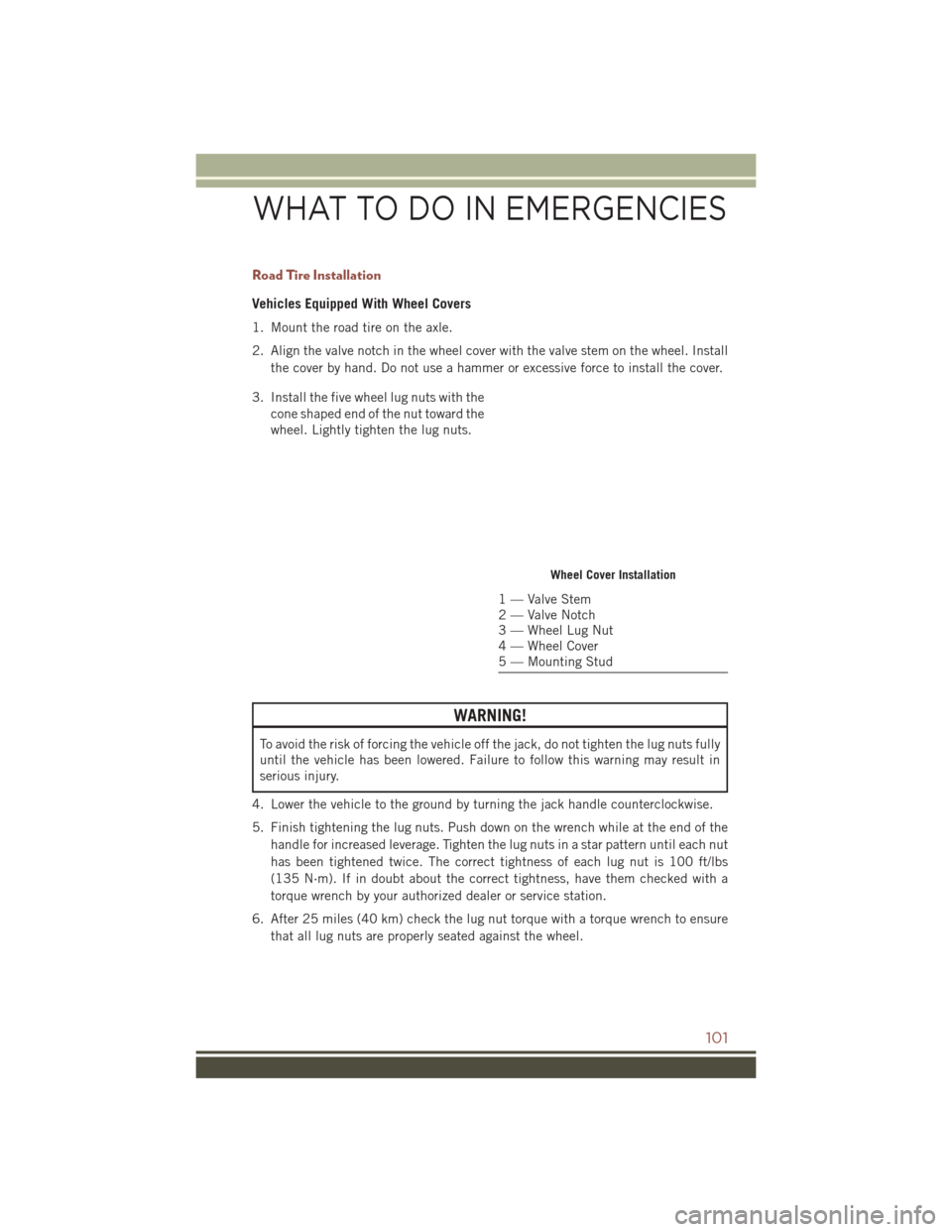
Wheel Cover Installation
1 — Valve Stem
2 — Valve Notch
3 — Wheel Lug Nut
4 — Wheel Cover
5 — Mounting Stud
WHAT TO DO IN EMERGENCIES
101
Page 104 of 148
Vehicles Without Wheel Covers
1. Mount the road tire on the axle.
2. Install the remaining lug nuts with the cone shaped end of the nut toward thewheel. Lightly tighten the lug nuts.
WARNING!
To avoid the risk of forcing the vehicle off the jack, do not fully tighten the lug nuts
until the vehicle has been lowered. Failure to follow this warning may result in
serious injury.
3. Lower the vehicle to the ground by turning the jack handle counterclockwise.
4. Finish tightening the lug nuts. Push down on the wrench while at the end of the handle for increased leverage. Tighten the lug nuts in a star pattern until each nut
has been tightened twice. The correct tightness of each lug nut is 100 ft/lbs
(135 N·m). If in doubt about the correct tightness, have them checked with a
torque wrench by your authorized dealer or service station.
5. After 25 miles (40 km) check the lug nut torque with a torque wrench to ensure that all lug nuts are properly seated against the wheel.
JUMP-STARTING PROCEDURES
If your vehicle has a discharged battery it can be jump-started using a set of jumper
cables and a battery in another vehicle or by using a portable battery booster pack.
Jump-starting can be dangerous if done improperly so please follow the procedures
in this section carefully.
NOTE:
When using a portable battery booster pack follow the manufacturer’s operating
instructions and precautions.
CAUTION!
Do not use a portable battery booster pack or any other booster source with a
system voltage greater than 12 Volts or damage to the battery, starter motor,
alternator or electrical system may occur.
WARNING!
Do not attempt jump-starting if the battery is frozen. It could rupture or explode
and cause personal injury.
WHAT TO DO IN EMERGENCIES
102
Page 106 of 148
WARNING!
• Take care to avoid the radiator cooling fan whenever the hood is raised. It canstart anytime the ignition switch is ON. You can be injured by moving fan
blades.
• Remove any metal jewelry such as rings, watch bands and bracelets that could
make an inadvertent electrical contact. You could be seriously injured.
• Batteries contain sulfuric acid that can burn your skin or eyes and generate
hydrogen gas which is flammable and explosive. Keep open flames or sparks
away from the battery.
1. Set the parking brake, shift the automatic transmission into PARK (manual transmission to NEUTRAL) and turn the ignition to LOCK.
2. Turn off the heater, radio, and all unnecessary electrical accessories.
3. If using another vehicle to jump-start the battery, park the vehicle within the jumper cables reach, set the parking brake and make sure the ignition is OFF.
WARNING!
Do not allow vehicles to touch each other as this could establish a ground
connection and personal injury could result.
Jump-Starting Procedure
WARNING!
Failure to follow this jump-starting procedure could result in personal injury or
property damage due to battery explosion.
CAUTION!
Failure to follow these procedures could result in damage to the charging system
of the booster vehicle or the discharged vehicle.
NOTE:
Remove Air Intake before proceeding with this Jump-Starting procedure.
Connecting The Jumper Cables
1. Connect the positive (+)end of the jumper cable to the positive (+)post of the
discharged vehicle.
2. Connect the opposite end of the positive (+)jumper cable to the positive (+)post
of the booster battery.
3. Connect the negative end (-)of the jumper cable to the negative (-)post of the
booster battery.
WHAT TO DO IN EMERGENCIES
104
Page 111 of 148
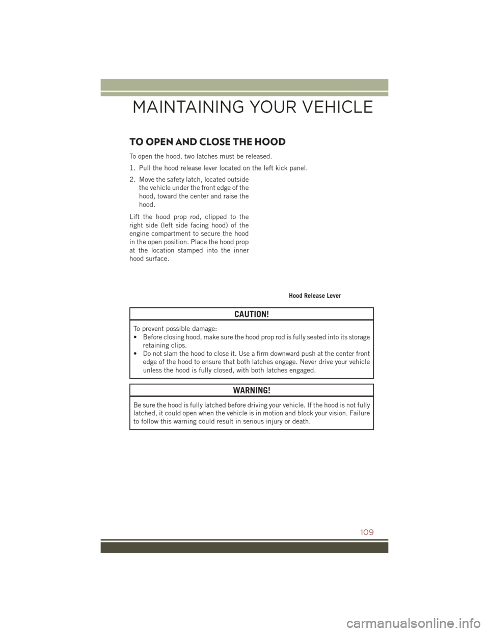
TO OPEN AND CLOSE THE HOOD
To open the hood, two latches must be released.
1. Pull the hood release lever located on the left kick panel.
2. Move the safety latch, located outsidethe vehicle under the front edge of the
hood, toward the center and raise the
hood.
Lift the hood prop rod, clipped to the
right side (left side facing hood) of the
engine compartment to secure the hood
in the open position. Place the hood prop
at the location stamped into the inner
hood surface.
CAUTION!
To prevent possible damage:
• Before closing hood, make sure the hood prop rod is fully seated into its storage retaining clips.
• Do not slam the hood to close it. Use a firm downward push at the center front
edge of the hood to ensure that both latches engage. Never drive your vehicle
unless the hood is fully closed, with both latches engaged.
WARNING!
Be sure the hood is fully latched before driving your vehicle. If the hood is not fully
latched, it could open when the vehicle is in motion and block your vision. Failure
to follow this warning could result in serious injury or death.
Hood Release Lever
MAINTAINING YOUR VEHICLE
109
Page 123 of 148
FUSES
WARNING!
• When replacing a blown fuse, always use an appropriate replacement fuse withthe same amp rating as the original fuse. Never replace a fuse with another
fuse of higher amp rating. Never replace a blown fuse with metal wires or any
other material. Failure to use proper fuses may result in serious personal injury,
fire and/or property damage.
• Before replacing a fuse, make sure that the ignition is off and that all the other
services are switched off and/or disengaged.
• If the replaced fuse blows again, contact an authorized dealer.
• If a general protection fuse for safety systems (air bag system, braking system),
power unit systems (engine system, gearbox system) or steering system blows,
contact an authorized dealer.
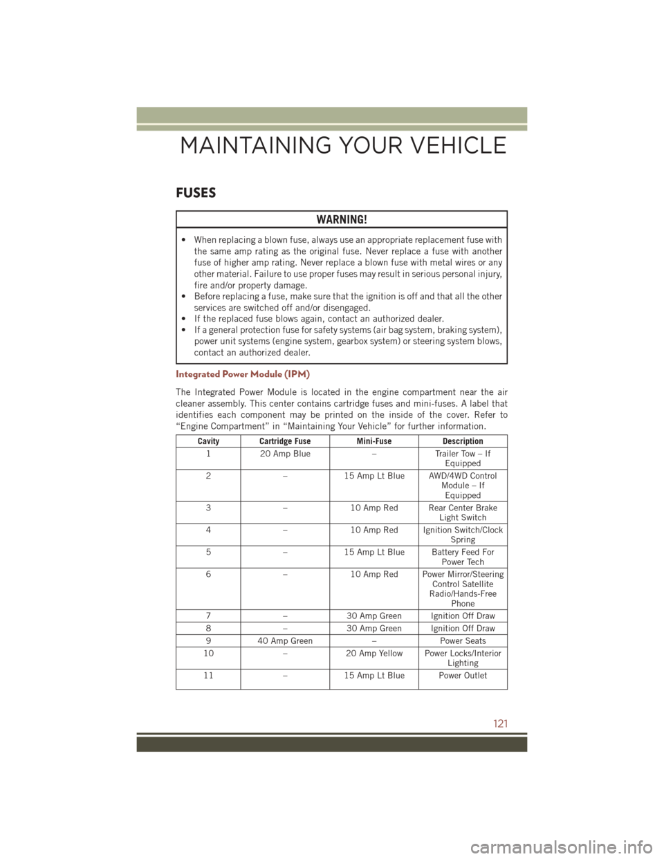
Integrated Power Module (IPM)
The Integrated Power Module is located in the engine compartment near the air
cleaner assembly. This center contains cartridge fuses and mini-fuses. A label that
identifies each component may be printed on the inside of the cover. Refer to
“Engine Compartment” in “Maintaining Your Vehicle” for further information.
Cavity Cartridge Fuse Mini-FuseDescription
1 20 Amp Blue –Trailer Tow – If
Equipped
2 –15 Amp Lt Blue AWD/4WD Control
Module – IfEquipped
3 –10 Amp Red Rear Center Brake
Light Switch
4 –10 Amp Red Ignition Switch/Clock
Spring
5 –15 Amp Lt Blue Battery Feed For
Power Tech
6 –10 Amp Red Power Mirror/Steering
Control Satellite
Radio/Hands-Free Phone
7 –30 Amp Green Ignition Off Draw
8 –30 Amp Green Ignition Off Draw
9 40 Amp Green –Power Seats
10 –20 Amp Yellow Power Locks/Interior
Lighting
11 –15 Amp Lt Blue Power Outlet
MAINTAINING YOUR VEHICLE
121
Page 124 of 148
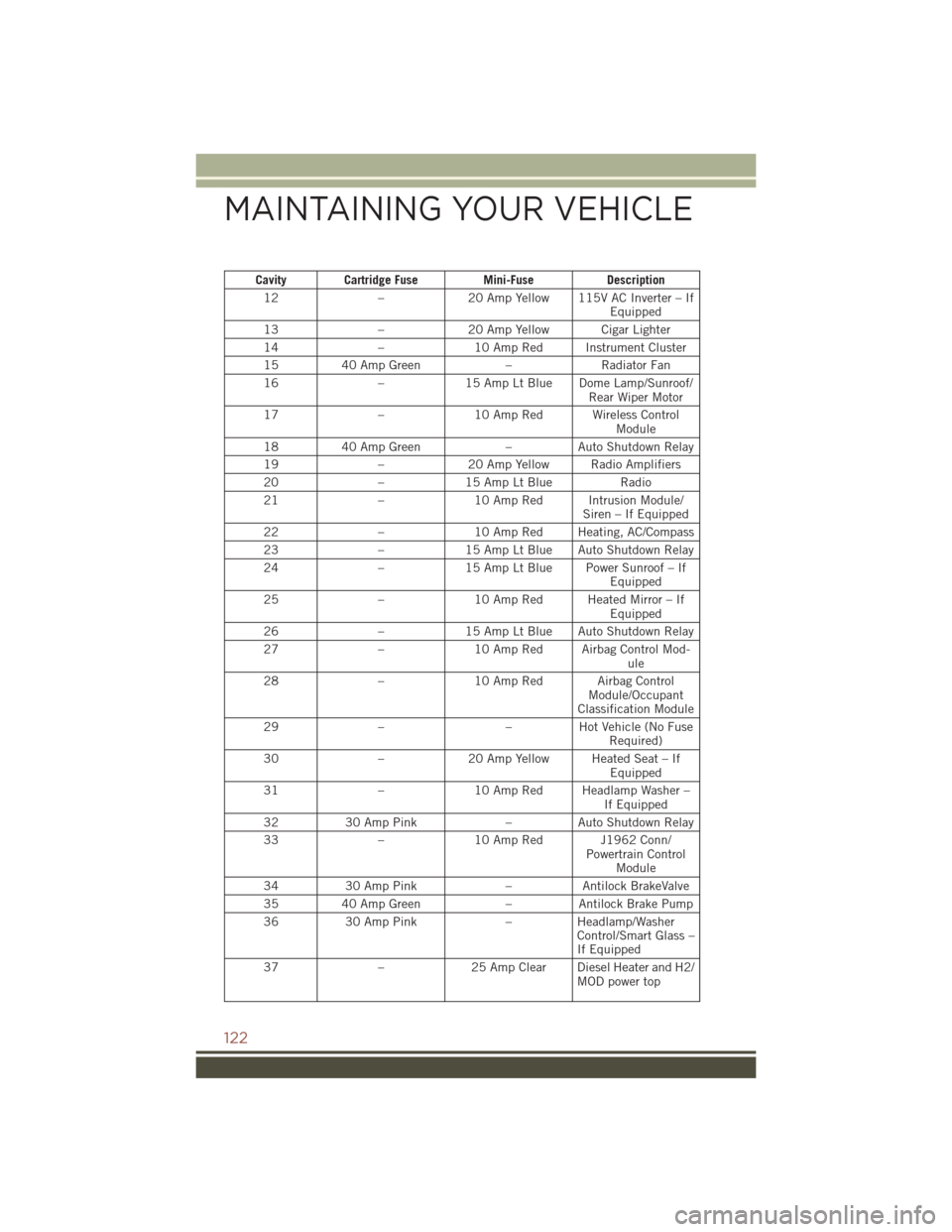
Cavity Cartridge FuseMini-FuseDescription
12 –20 Amp Yellow 115V AC Inverter – If
Equipped
13 –20 Amp Yellow Cigar Lighter
14 –10 Amp Red Instrument Cluster
15 40 Amp Green –Radiator Fan
16 –15 Amp Lt Blue Dome Lamp/Sunroof/
Rear Wiper Motor
17 –10 Amp Red Wireless Control
Module
18 40 Amp Green –Auto Shutdown Relay
19 –20 Amp Yellow Radio Amplifiers
20 –15 Amp Lt Blue Radio
21 –10 Amp Red Intrusion Module/
Siren – If Equipped
22 –10 Amp Red Heating, AC/Compass
23 –15 Amp Lt Blue Auto Shutdown Relay
24 –15 Amp Lt Blue Power Sunroof – If
Equipped
25 –10 Amp Red Heated Mirror – If
Equipped
26 –15 Amp Lt Blue Auto Shutdown Relay
27 –10 Amp Red Airbag Control Mod-
ule
28 –10 Amp Red Airbag Control
Module/Occupant
Classification Module
29 – –Hot Vehicle (No Fuse
Required)
30 –20 Amp Yellow Heated Seat – If
Equipped
31 –10 Amp Red Headlamp Washer –
If Equipped
32 30 Amp Pink –Auto Shutdown Relay
33 –10 Amp Red J1962 Conn/
Powertrain ControlModule
34 30 Amp Pink –Antilock BrakeValve
35 40 Amp Green –Antilock Brake Pump
36 30 Amp Pink –Headlamp/Washer
Control/Smart Glass –
If Equipped
37 –25 Amp Clear Diesel Heater and H2/
MOD power top
MAINTAINING YOUR VEHICLE
122
Page 131 of 148
AUTHENTIC ACCESSORIES BY MOPAR
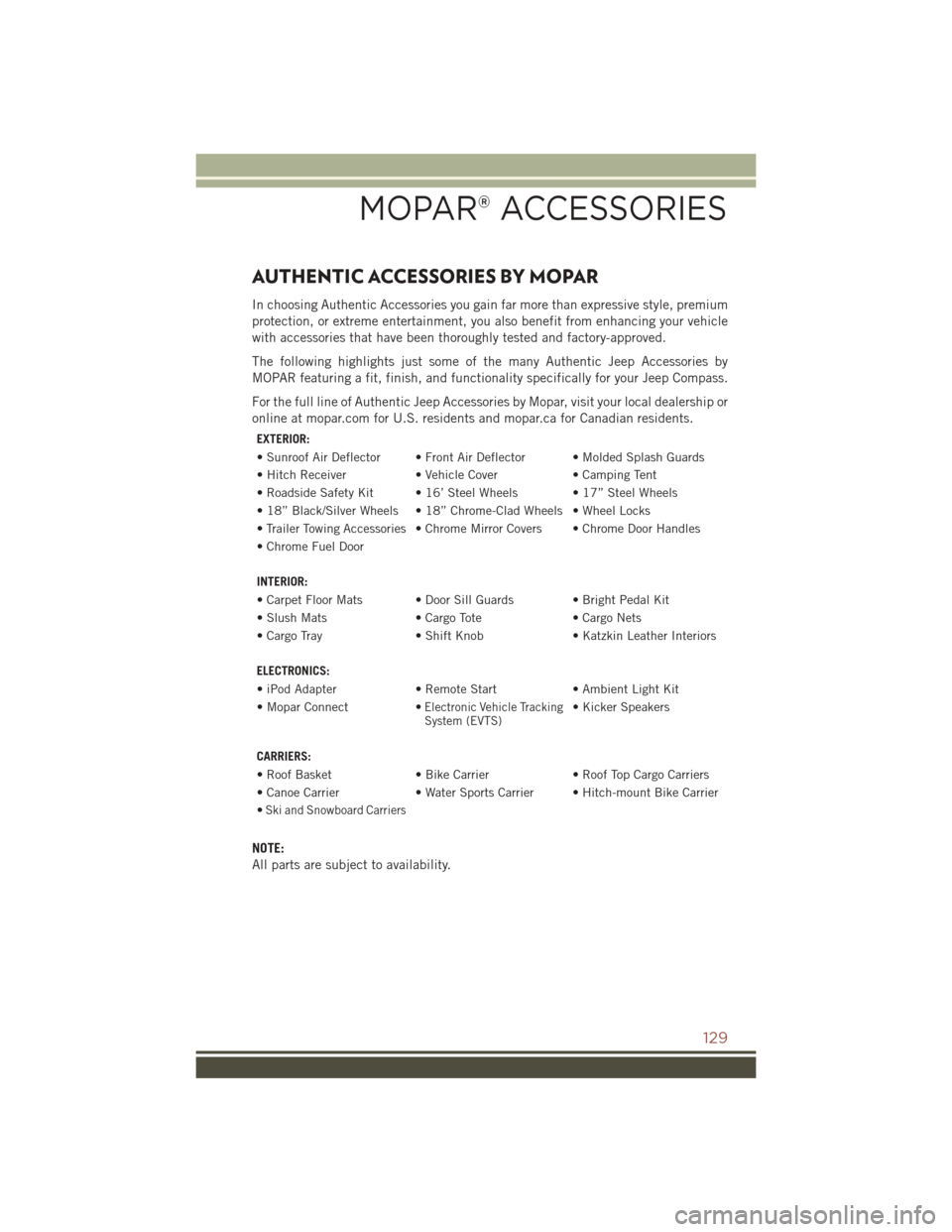
In choosing Authentic Accessories you gain far more than expressive style, premium
protection, or extreme entertainment, you also benefit from enhancing your vehicle
with accessories that have been thoroughly tested and factory-approved.
The following highlights just some of the many Authentic Jeep Accessories by
MOPAR featuring a fit, finish, and functionality specifically for your Jeep Compass.
For the full line of Authentic Jeep Accessories by Mopar, visit your local dealership or
online at mopar.com for U.S. residents and mopar.ca for Canadian residents.
EXTERIOR:
• Sunroof Air Deflector • Front Air Deflector • Molded Splash Guards
• Hitch Receiver • Vehicle Cover • Camping Tent
• Roadside Safety Kit • 16’ Steel Wheels • 17” Steel Wheels
• 18” Black/Silver Wheels • 18” Chrome-Clad Wheels • Wheel Locks
• Trailer Towing Accessories • Chrome Mirror Covers • Chrome Door Handles
• Chrome Fuel Door
INTERIOR:
• Carpet Floor Mats • Door Sill Guards • Bright Pedal Kit
• Slush Mats • Cargo Tote • Cargo Nets
• Cargo Tray • Shift Knob • Katzkin Leather Interiors
ELECTRONICS:
• iPod Adapter • Remote Start • Ambient Light Kit
• Mopar Connect •
Electronic Vehicle TrackingSystem (EVTS)• Kicker Speakers
CARRIERS:
• Roof Basket • Bike Carrier• Roof Top Cargo Carriers
• Canoe Carrier • Water Sports Carrier • Hitch-mount Bike Carrier
•
Ski and Snowboard Carriers
NOTE:
All parts are subject to availability.
MOPAR® ACCESSORIES
129
Page 132 of 148
FREQUENTLY ASKED QUESTIONS
GETTING STARTED
• How do I install my LATCH Equipped Child Seat? pg. 18
• How do my heated seats operate? pg. 27
ELECTRONICS
• Which radio is in my vehicle?• Uconnect 130 pg. 44
• Uconnect 130 with Satellite Radio pg. 46
• Uconnect 230 pg. 49
• Uconnect 430/430N pg. 52
• How do I activate the Audio Jack?
• Uconnect 130 pg. 51
• Uconnect 130 with Satellite Radio pg. 51
• Uconnect 230 pg. 51
• Uconnect 430/430N pg. 57
• How do I set the clock on my radio?
• Uconnect 130 pg. 50
• Uconnect 130 with Satellite Radio pg. 50
• Uconnect 230 pg. 50
• Uconnect 430/430N pg. 53
• How do I use the Navigation feature? pg. 61
• How do I pair my cell phone via Bluetooth with the Uconnect Hands-Free Voice Activation System? pg. 70
• How do I configure my Universal Garage Door Opener (HomeLink)? pg. 78
UTILITY
• How do I know how much I can tow with my Jeep Compass? pg. 85
WHAT TO DO IN EMERGENCIES
• What do I do if my TPMS warning light is blinking? pg. 88
• How do I change a flat tire? pg. 94
• How do I Jump-Start my vehicle? pg. 102
FAQ
130
Page 133 of 148
MAINTAINING YOUR VEHICLE
• Where is my Fuse Block located? pg. 121
• What type of oil do I use? pg. 114
• How often should I change my engine’s oil? pg. 116
• What should my tire pressure be set at? pg. 123
FAQ
131