engine JEEP COMPASS 2017 2.G Owner's Manual
[x] Cancel search | Manufacturer: JEEP, Model Year: 2017, Model line: COMPASS, Model: JEEP COMPASS 2017 2.GPages: 429, PDF Size: 3.46 MB
Page 100 of 429

1. Speedometer•The Speedometer shows the vehicle speed in miles per
hour (MPH) and kilometers per hour (km/h).
Odometer Display / Trip Odometer Display
This display indicates the total distance the vehicle has
been driven.
NOTE: U.S. Federal regulations require that upon transfer
of vehicle ownership, the seller certify to the purchaser the
correct mileage that the vehicle has been driven. If your
odometer needs to be repaired or serviced, the repair
technician should leave the odometer reading the same as
it was before the repair or service. If s/he cannot do so,
then the odometer must be set at zero, and a sticker must
be placed in the door jamb stating what the mileage was
before the repair or service. It is a good idea for you to
make a record of the odometer reading before the repair/
service, so that you can be sure that it is properly reset, or
that the door jamb sticker is accurate if the odometer must
be reset at zero. 2. Tachometer
•This gauge measures engine revolutions per minute
(RPM x 1000). Before the pointer reaches the red area,
ease up on the accelerator to prevent engine damage.
3. Temperature Gauge •The temperature gauge shows engine coolant tem-
perature. Any reading within the normal range indi-
cates that the engine cooling system is operating
satisfactorily.
• The gauge pointer will likely indicate a higher tem-
perature when driving in hot weather or up mountain
grades. It should not be allowed to exceed the upper
limits of the normal operating range.
CAUTION!
Driving with a hot engine cooling system could dam-
age your vehicle. If the temperature gauge reads “H”
pull over and stop the vehicle. Idle the vehicle with the
air conditioner turned off until the pointer drops back
into the normal range. If the pointer remains on the
“H”, turn the engine off immediately and call an
authorized dealer for service.
98 GETTING TO KNOW YOUR INSTRUMENT PANEL
Page 101 of 429
WARNING!
A hot engine cooling system is dangerous. You or
others could be badly burned by steam or boiling
coolant. You may want to call an authorized dealer for
service if your vehicle overheats. If you decide to look
under the hood yourself, see “Maintaining Your Ve-
hicle”. Follow the warnings under the Cooling System
Pressure Cap paragraph.
4. Instrument Cluster Display — If Equipped / Odometer Display / Trip Odometer Display
Instrument Cluster Display — If Equipped
The instrument cluster display features a driver-interactive
display that is located in the instrument cluster. Refer to
“Instrument Cluster Display” in this section for further
information.
Message Display Area
When the appropriate conditions exist, the following
odometer messages will display:
door ............................. Door Open
gATE ........................... Liftgate OpenLoW tirE
.....................LowTirePr essure
gASCAP ........................ Fuel Cap Fault
noFUSE ........................... Fuse Fault
CHAngE OIL ................Oil Change Required
LoCOOL .........................Low Coolant
NOTE: Some of the above warnings will be displayed in
the instrument cluster display area located in the instru-
ment cluster.
Refer to ”Instrument Cluster Display” in this section for
further information.
LoW tirE
When the appropriate condition exists, the odometer dis-
play will toggle between LoW and tirE for three cycles.
gASCAP
If the vehicle diagnostic system determines that the fuel
filler cap is loose, improperly installed, or damaged, a
“gASCAP” message will display in the odometer display
area. Tighten the fuel filler cap properly and push the STEP
4
GETTING TO KNOW YOUR INSTRUMENT PANEL 99
Page 102 of 429

button on the steering wheel to turn off the message. If the
problem continues, the message will appear the next time
the vehicle is started.
noFUSE
If the vehicle diagnostic system determines that the Igni-
tion Off Draw (IOD) fuse is improperly installed, or
damaged, a “noFUSE” message will display in the odom-
eter display area. Refer to “Fuses” in “In Case Of Emer-
gency” for further information on fuses and fuse locations.
CHAngE OIL
Your vehicle is equipped with an engine oil change indi-
cator system. The odometer display will toggle between
CHAngEandOilfor approximately 12 seconds, after a
single chime has sounded, to indicate the next scheduled
oil change interval. The engine oil change indicator system
is duty cycle-based, which means the engine oil change
interval may fluctuate dependent upon your personal
driving style.
5. Fuel Gauge
•The pointer shows the level of fuel in the fuel tank
when the ignition is in the ON/RUN position
•
The fuel pump symbol points to the side of the
vehicle where the fuel door is located. INSTRUMENT CLUSTER DISPLAY
Your vehicle may be equipped with an instrument cluster
display, which offers useful information to the driver. With
the ignition in the STOP/OFF position (and the key
removed, for vehicles with mechanical key), opening/
closing of a door will activate the display for viewing, and
display the total miles or kilometers in the odometer. Your
instrument cluster display is designed to display important
information about your vehicle’s systems and features.
Using a driver interactive display located on the instru-
ment panel, your instrument cluster display can show you
how systems are working and give you warnings when
they aren’t. The steering wheel mounted controls allow
you to scroll through and enter the main menus and
submenus. You can access the specific information you
want and make selections and adjustments.
Interactive Display And Controls
The instrument cluster display features a driver-interactive
display that is located in the instrument cluster.
100 GETTING TO KNOW YOUR INSTRUMENT PANEL
Page 105 of 429
•Remote Start Aborted — Fuel Low
• Remote Start Aborted — System Fault
• Key In Ignition
• Low Tire
• Low Tire Pressure Display for Premium TPM System
• Service TPM System
Oil Change Indicator System
Your vehicle is equipped with an engine oil change indi-
cator system. The “Oil Change Required” message will
display in the instrument cluster display for approximately
five seconds after a single chime has sounded to indicate
the next scheduled oil change interval. The engine oil
change indicator system is duty-cycle based, which means
the engine oil change interval may fluctuate dependent
upon your personal driving style.
Unless reset, this message will continue to display each
time you place the ignition in the ON/RUN position. To
turn off the message temporarily, push and release the Trip
Odometer button on the instrument cluster. To reset the oil
change indicator system (after performing the scheduled
maintenance), refer to the following procedure. 1. Place the ignition in the ON position.
Do not start the
engine.
2. Fully push the accelerator pedal, slowly, three times within 10 seconds.
3. Place the ignition in the OFF/LOCK position.
NOTE: If the indicator message illuminates when you
start the vehicle, the oil change indicator system did not
reset. If necessary, repeat this procedure.Instrument Cluster Display Functions
• Compass/Temperature/Audio
• Average Fuel Economy
• Distance To Empty (DTE)
• Units In
• Elapsed Time
• Tire Pressure Monitor (TPM)
• Personal Settings
4
GETTING TO KNOW YOUR INSTRUMENT PANEL 103
Page 110 of 429

Manual Compass Calibration
If the compass appears erratic and the “CAL” indicator
does not appear in the instrument cluster display, you must
put the compass into the Calibration Mode manually as
follows:
1. Start the engine. Leave the gear selector in PARK inorder to enter the instrument cluster display Program-
ming Menus.
2. Push and release the MENUbutton until the Personal
Settings (Customer-Programmable Features) menu dis-
plays in the instrument cluster display.
3. Push and release the down
arrow button until
“Calibrate Compass” displays in the instrument clus-
ter display.
4. Push and release the rightarrow button to start the
calibration. The “CAL” indicator will display in the
instrument cluster display.
5. Complete one or more 360 – degree turns (in an area free from large metal or metallic objects) until the “CAL”
indicator turns off. The compass will now function
normally.
Compass Variance
Compass Variance is the difference between Magnetic
North and Geographic North. To compensate for the
differences, the variance should be set for the zone where
the vehicle is driven, per the zone map. Once properly set,
the compass will automatically compensate for the differ-
ences and provide the most accurate compass heading.
NOTE: Magnetic materials should be kept away from the
top of the right rear quarter window. This is where the
compass sensor is located.
Compass Variance Map
108 GETTING TO KNOW YOUR INSTRUMENT PANEL
Page 111 of 429
1. Turn the ignition switch ON.
2. Push and hold thecompassbutton for approximately
two seconds.
3. Push and release the down
arrow button until
“Compass Variance” message and the last variance
zone number displays in the instrument cluster dis-
play.
4. Push and release the rightarrow button until the
proper variance zone is selected according to the
map.
5. Push and release the compassbutton to exit.
MINI-TRIP COMPUTER — IF EQUIPPED
The Mini-Trip Computer is located in the instrument
cluster and features a driver-interactive trip information
and temperature display.
NOTE:The system will display the last known outside
temperature when starting the vehicle and may need to be
driven several minutes before the updated temperature is
displayed. Engine temperature can also affect the dis-
played temperature; therefore, temperature readings are
not updated when the vehicle is not moving.
Control Buttons
STEP Button
Push the STEPbutton located on the steering wheel to
scroll through sub menus (i.e., Temperature, Trip Func-
tions: Odometer, Trip A, Trip B).
RESET Button
To reset the display shown, turn the ignition to the ON
position, then push and hold the RESETbutton located on
the steering wheel.
Mini-Trip Control Buttons
4
GETTING TO KNOW YOUR INSTRUMENT PANEL 109
Page 116 of 429

Oil Pressure Warning Light
Red TelltaleLight What It Means
Oil Pressure Warning Light
This light indicates low engine oil pressure. If the light turns on while driving, stop the vehicle
and shut off the engine as soon as possible. A chime will sound when this light turns on.
Do not operate the vehicle until the cause is corrected. This light does not indicate how much oil
is in the engine. The engine oil level must be checked under the hood.
Battery Charge Warning Light
Red Telltale
Light What It Means
Battery Charge Warning Light
This light illuminates when the battery is not charging properly. If it stays on while the engine is
running, there may be a malfunction with the charging system. Contact your authorized dealer as
soon as possible. This indicates a possible problem with the electrical system or a related compo-
nent.
If jump starting is required, refer to “Jump-Starting” in “In Case Of Emergency.”
114 GETTING TO KNOW YOUR INSTRUMENT PANEL
Page 117 of 429
Electronic Throttle Control (ETC) Warning Light
Red TelltaleLight What It Means
Electronic Throttle Control (ETC) Warning Light
This light informs you of a problem with the Electronic Throttle Control (ETC) system. If a prob-
lem is detected while the engine is running, the light will either stay on or flash depending on
the nature of the problem. Cycle the ignition key when the vehicle is safely and completely
stopped and the transmission is placed in the PARK position. The light should turn off. If the
light remains on with the vehicle under power, your vehicle will usually be drivable; however,
see an authorized dealer for service as soon as possible.
If the light continues to flash when the engine vehicle under power, immediate service is re-
quired and you may experience reduced performance, and your vehicle may require towing. The
light will come on when the ignition is placed in the ON/RUN position and remain on briefly as
a bulb check. If the light does not come on during starting, have the system checked by an au-
thorized dealer.
4
GETTING TO KNOW YOUR INSTRUMENT PANEL 115
Page 118 of 429
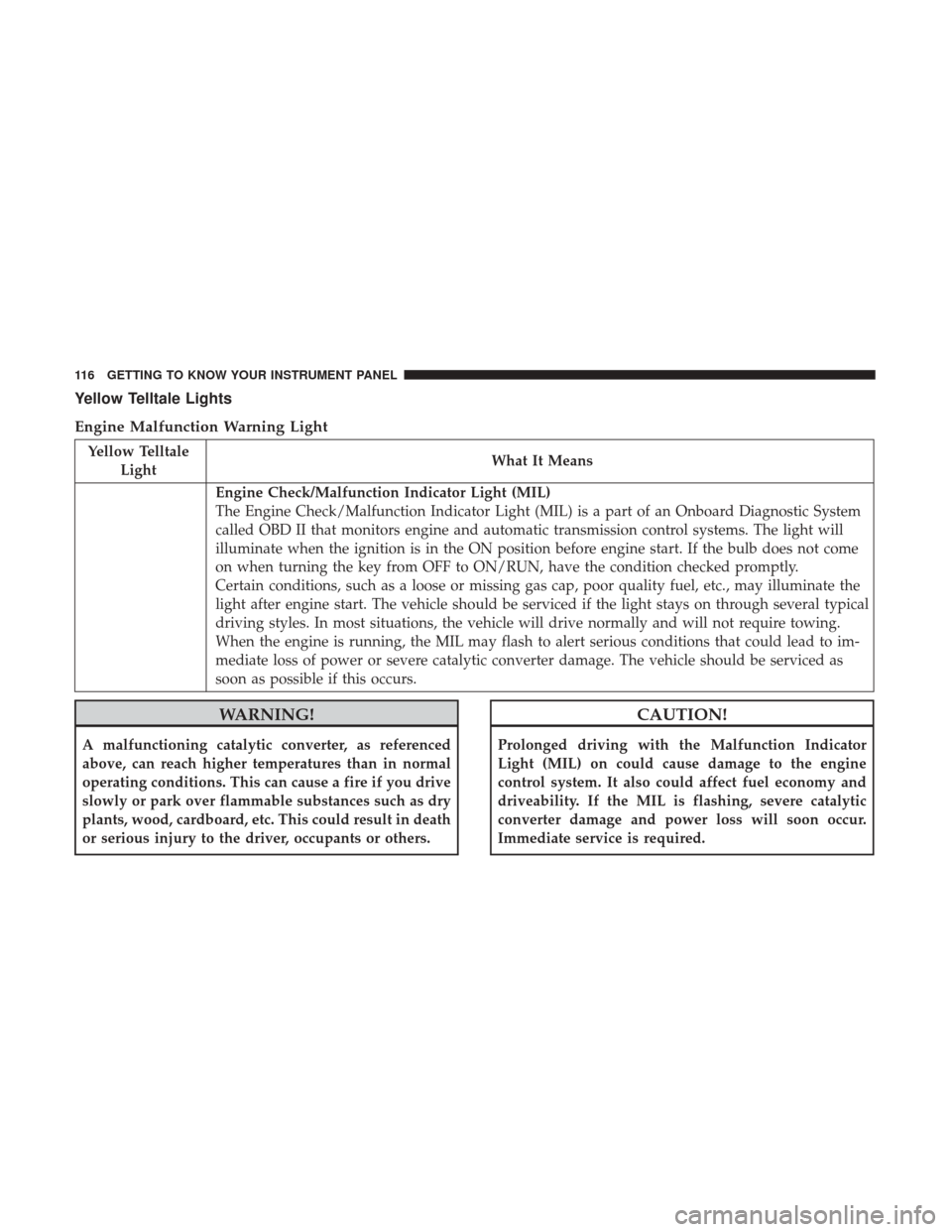
Yellow Telltale Lights
Engine Malfunction Warning Light
Yellow TelltaleLight What It Means
Engine Check/Malfunction Indicator Light (MIL)
The Engine Check/Malfunction Indicator Light (MIL) is a part of an Onboard Diagnostic System
called OBD II that monitors engine and automatic transmission control systems. The light will
illuminate when the ignition is in the ON position before engine start. If the bulb does not come
on when turning the key from OFF to ON/RUN, have the condition checked promptly.
Certain conditions, such as a loose or missing gas cap, poor quality fuel, etc., may illuminate the
light after engine start. The vehicle should be serviced if the light stays on through several typical
driving styles. In most situations, the vehicle will drive normally and will not require towing.
When the engine is running, the MIL may flash to alert serious conditions that could lead to im-
mediate loss of power or severe catalytic converter damage. The vehicle should be serviced as
soon as possible if this occurs.
WARNING!
A malfunctioning catalytic converter, as referenced
above, can reach higher temperatures than in normal
operating conditions. This can cause a fire if you drive
slowly or park over flammable substances such as dry
plants, wood, cardboard, etc. This could result in death
or serious injury to the driver, occupants or others.
CAUTION!
Prolonged driving with the Malfunction Indicator
Light (MIL) on could cause damage to the engine
control system. It also could affect fuel economy and
driveability. If the MIL is flashing, severe catalytic
converter damage and power loss will soon occur.
Immediate service is required.
116 GETTING TO KNOW YOUR INSTRUMENT PANEL
Page 121 of 429
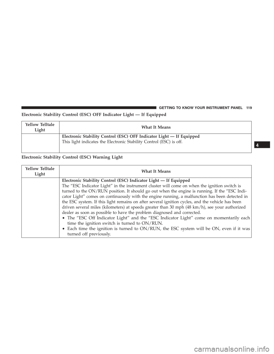
Electronic Stability Control (ESC) OFF Indicator Light — If Equipped
Yellow TelltaleLight What It Means
Electronic Stability Control (ESC) OFF Indicator Light — If Equipped
This light indicates the Electronic Stability Control (ESC) is off.
Electronic Stability Control (ESC) Warning Light
Yellow Telltale
Light What It Means
Electronic Stability Control (ESC) Indicator Light — If Equipped
The “ESC Indicator Light” in the instrument cluster will come on when the ignition switch is
turned to the ON/RUN position. It should go out when the engine is running. If the “ESC Indi-
cator Light” comes on continuously with the engine running, a malfunction has been detected in
the ESC system. If this light remains on after several ignition cycles, and the vehicle has been
driven several miles (kilometers) at speeds greater than 30 mph (48 km/h), see your authorized
dealer as soon as possible to have the problem diagnosed and corrected.
•
The “ESC Off Indicator Light” and the “ESC Indicator Light” come on momentarily each
time the ignition switch is turned to ON/RUN.
• Each time the ignition is turned to ON/RUN, the ESC system will be ON, even if it was
turned off previously. 4
GETTING TO KNOW YOUR INSTRUMENT PANEL 119