ECO mode JEEP COMPASS 2018 Owner handbook (in English)
[x] Cancel search | Manufacturer: JEEP, Model Year: 2018, Model line: COMPASS, Model: JEEP COMPASS 2018Pages: 348, PDF Size: 6.03 MB
Page 48 of 348
Climate Control Functions
A/C (Air Conditioning)
The Air Conditioning (A/C) button allows the
operator to manually activate or deactivate
the air conditioning system. When the air
conditioning system is turned on, cool dehu-
midified air will flow through the outlets into
the cabin. For improved fuel economy, press
the A/C button to turn off the air conditioning
and manually adjust the blower and airflow
mode settings. Also, make sure to select only
Panel, Bi-Level, or Floor modes.
NOTE:
• If fog or mist appears on the windshield or
side glass, select Defrost mode and in-
crease blower speed if needed.
• If your air conditioning performance seems
lower than expected, check the front of the
A/C condenser (located in front of the ra-
diator), for an accumulation of dirt or in-
sects. Clean with a gentle water spray from
the front of the radiator and through the
condenser.MAX A/C
MAX A/C sets the control for maximum cool-
ing performance. Press and release to toggle
between MAX A/C and the prior settings. The
button illuminates when MAX A/C is ON.
Pressing blower speed, temperature, recircu-
lation, or mode settings, will cause the MAX
A/C operation to switch to the selected set-
ting and MAX A/C to exit.
Recirculation
When outside air contains smoke, odors, or
high humidity, or if rapid cooling is desired,
you may wish to recirculate interior air by
pressing the Recirculation control button.
The Recirculation indicator will illuminate
when this button is selected. Press the but-
ton a second time to turn off the Recircula-
tion mode and allow outside air into the
vehicle.NOTE:
In cold weather, use of Recirculation mode
may lead to excessive window fogging. The
Recirculation feature may be unavailable
(button on the touchscreen greyed out) if
conditions exist that could create fogging on
the inside of the windshield.
Automatic Temperature Control (ATC) —
If Equipped
Automatic Operation
1. Push the AUTO button on the faceplate,
or the AUTO button on the touchscreen (if
equipped) on the Automatic Temperature
Control (ATC) Panel.
2. Next, adjust the temperature you would
like the system to maintain by adjusting
the driver and passenger temperature
control buttons. Once the desired tem-
perature is displayed, the system will
achieve and automatically maintain that
comfort level.
GETTING TO KNOW YOUR VEHICLE
46
Page 49 of 348
3. When the system is set up for your comfort
level, it is not necessary to change the
settings. You will experience the greatest
efficiency by simply allowing the system
to function automatically.
NOTE:
• It is not necessary to move the temperature
settings for cold or hot vehicles. The system
automatically adjusts the temperature,
mode, and blower speed to provide comfort
as quickly as possible.
• The temperature can be displayed in U.S.
or Metric units by selecting the US/Metric
customer-programmable feature.
To provide you with maximum comfort in the
Automatic mode during cold start-ups, the
blower fan will remain on low until the engine
warms up. The blower will increase in speed
and transition into Auto mode.
Manual Operation Override
This system offers a full complement of
manual override features. The AUTO symbol
in the front ATC display will be turned off
when the system is being used in the manual
mode.
Operating Tips
Summer Operation
The engine cooling system must be protected
with a high-quality antifreeze coolant to pro-
vide proper corrosion protection and to pro-
tect against engine overheating. OAT coolant
(conforming to MS.90032) is recommended.
Winter Operation
To ensure the best possible heater and de-
froster performance, make sure the engine
cooling system is functioning properly and
the proper amount, type, and concentration
of coolant is used. Use of the Air Recircula-
tion mode during Winter months is not rec-
ommended, because it may cause window
fogging.
Vacation/Storage
Before you store your vehicle, or keep it out of
service (i.e., vacation) for two weeks or more,
run the air conditioning system at idle for
about five minutes, in fresh air with the
blower setting on high. This will ensure ad-equate system lubrication to minimize the
possibility of compressor damage when the
system is started again.
Window Fogging
Vehicle windows tend to fog on the inside in
mild, rainy, and/or humid weather. To clear
the windows, select Defrost or Mix mode and
increase the front blower speed. Do not use
the Recirculation mode without A/C for long
periods, as fogging may occur.
Outside Air Intake
Make sure the air intake, located directly in
front of the windshield, is free of obstruc-
tions, such as leaves. Leaves collected in the
air intake may reduce airflow, and if they
enter the plenum, they could plug the water
drains. In Winter months, make sure the air
intake is clear of ice, slush, and snow.
Cabin Air Filter
The climate control system filters out dust
and pollen from the air. Contact an autho-
rized dealer to service your cabin air filter,
and to have it replaced when needed.
47
Page 52 of 348
POWER SUNROOF — IF
EQUIPPED
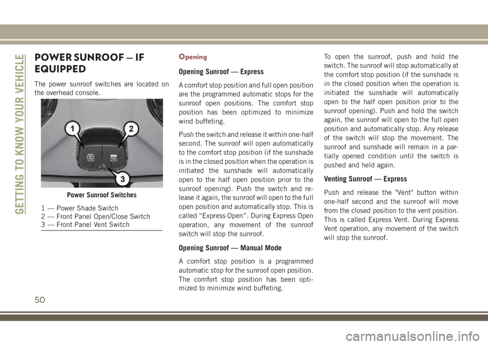
The power sunroof switches are located on
the overhead console.
Opening
Opening Sunroof — Express
A comfort stop position and full open position
are the programmed automatic stops for the
sunroof open positions. The comfort stop
position has been optimized to minimize
wind buffeting.
Push the switch and release it within one-half
second. The sunroof will open automatically
to the comfort stop position (if the sunshade
is in the closed position when the operation is
initiated the sunshade will automatically
open to the half open position prior to the
sunroof opening). Push the switch and re-
lease it again, the sunroof will open to the full
open position and automatically stop. This is
called “Express Open”. During Express Open
operation, any movement of the sunroof
switch will stop the sunroof.
Opening Sunroof — Manual Mode
A comfort stop position is a programmed
automatic stop for the sunroof open position.
The comfort stop position has been opti-
mized to minimize wind buffeting.To open the sunroof, push and hold the
switch. The sunroof will stop automatically at
the comfort stop position (if the sunshade is
in the closed position when the operation is
initiated the sunshade will automatically
open to the half open position prior to the
sunroof opening). Push and hold the switch
again, the sunroof will open to the full open
position and automatically stop. Any release
of the switch will stop the movement. The
sunroof and sunshade will remain in a par-
tially opened condition until the switch is
pushed and held again.
Venting Sunroof — Express
Push and release the "Vent" button within
one-half second and the sunroof will move
from the closed position to the vent position.
This is called Express Vent. During Express
Vent operation, any movement of the switch
will stop the sunroof.Power Sunroof Switches
1 — Power Shade Switch
2 — Front Panel Open/Close Switch
3 — Front Panel Vent SwitchGETTING TO KNOW YOUR VEHICLE
50
Page 53 of 348
NOTE:
• If the sunshade is in the closed position
when the vent switch is pushed, the sun-
shade will automatically cycle to the half-
way open position prior to the sunroof open-
ing to the Vent position.
• When the sunroof is in a full open or a
partial open position, Express Vent opera-
tion is not available. You must push and
hold the vent switch to cycle the sunroof
from a slide open position to the vent posi-
tion. Sunroof movement will stop if the
switch is released prior to the sunroof
reaching the vent position.
Closing
Closing Sunroof — Express
Pull the switch and release it within one-half
second and the sunroof will close automati-
cally from any position. The sunroof will close
fully and stop automatically. This is called
“Express Close.” During Express Close opera-
tion, any other actuation of the switch will
stop the sunroof.
Closing Sunroof — Manual Mode
To close the sunroof, pull and hold the switch
in the close position. Any release of the
switch will stop the movement and the sun-
roof will remain in a partially closed condition
until the sunroof switch is pulled again.
Wind Buffeting
Wind buffeting can be described as the per-
ception of pressure on the ears or a
helicopter-type sound in the ears. Your ve-
hicle may exhibit wind buffeting with the
windows down, or the sunroof (if equipped) in
certain open or partially open positions. This
is a normal occurrence and can be mini-
mized. If the buffeting occurs with the rear
windows open, then open the front and rear
windows together to minimize the buffeting.
If the buffeting occurs with the sunroof open,
adjust the sunroof opening to minimize the
buffeting or open any window.
Power Sun Shade
Opening Power Shade — Express
Push the shade switch and release it within
one-half second and the shade will automati-
cally open to the halfway position and stop
automatically. Push the switch a second time
from the halfway position and the shade will
automatically open to the full open position
and stop automatically. This is called “Ex-
press Open”. During Express Open operation,
any movement of the shade switch will stop
the shade.
Opening Power Shade — Manual Mode
To open the shade, push and hold the switch.
The shade will open and stop automatically at
the half-open position. Push and hold the
shade switch again and the shade will open
automatically to the full-open position. Any
release of the switch will stop the movement
and the shade will remain in a partially
opened condition until the switch is pushed
again.
51
Page 54 of 348
Closing Power Shade — Express
Pull the switch and release it within one-half
second and the shade will close automati-
cally from any position. If the sunroof is
completely closed the shade will close fully
and stop automatically. This is called “Ex-
press Close”. During Express Close opera-
tion, any movement of the switch will stop
the shade.
NOTE:
If the sunroof is open, the shade will close to
the half-open position. Pulling the shade
close button again will automatically close
both the sunroof and shade completely.
Closing Power Shade — Manual Mode
To close the shade, pull and hold the switch
in the close position. Any release of the
switch will stop the movement and the shade
will remain in a partially closed condition
until the switch is pulled again.
Pinch Protection Feature
This feature will detect an obstruction in the
opening of the sunroof during Express Close
operation. If an obstruction in the path of the
sunroof is detected, the sunroof will auto-
matically retract. Remove the obstruction if
this occurs. Next, push the switch forward
and release to Express Close.
NOTE:
If three consecutive sunroof close attempts
result in Pinch Protect reversals, the fourth
close attempt will be a Manual Close move-
ment with Pinch Protect disabled.
WARNING!
• Do not let children play with the sunroof.
Never leave children unattended in a
vehicle, or with access to an unlocked
vehicle. Do not leave the key fob in or
near the vehicle, and do not leave the
ignition of a vehicle equipped with Key-
WARNING!
less Enter-N-Go in the ACC or ON/RUN
mode. Occupants, particularly unat-
tended children, can become entrapped
by the power sunroof while operating the
power sunroof switch. Such entrapment
may result in serious injury or death.
• In a collision, there is a greater risk of
being thrown from a vehicle with an
open sunroof. You could also be severely
injured or killed. Always fasten your seat
belt properly and make sure all passen-
gers are properly secured.
• Do not allow small children to operate
the sunroof. Never allow your fingers,
other body parts, or any object to project
through the sunroof opening. Injury may
result.
Sunroof Maintenance
Use only a non-abrasive cleaner and a soft
cloth to clean the glass panel.
GETTING TO KNOW YOUR VEHICLE
52
Page 62 of 348
INSTRUMENT CLUSTER
DISPLAY
Your vehicle may be equipped with an instru-
ment cluster display, which offers useful in-
formation to the driver. With the ignition in
the STOP/OFF mode, opening/closing of a
door will activate the display for viewing, and
display the total miles, or kilometers, in the
odometer. Your instrument cluster display is
designed to display important information
about your vehicle’s systems and features.
Using a driver interactive display located on
the instrument panel, your instrument clus-
ter display can show you how systems are
working and give you warnings when they
aren’t. The steering wheel mounted controls
allow you to scroll through and enter the main
menus and submenus. You can access the
specific information you want and make se-
lections and adjustments.
Instrument Cluster Display Location And
Controls
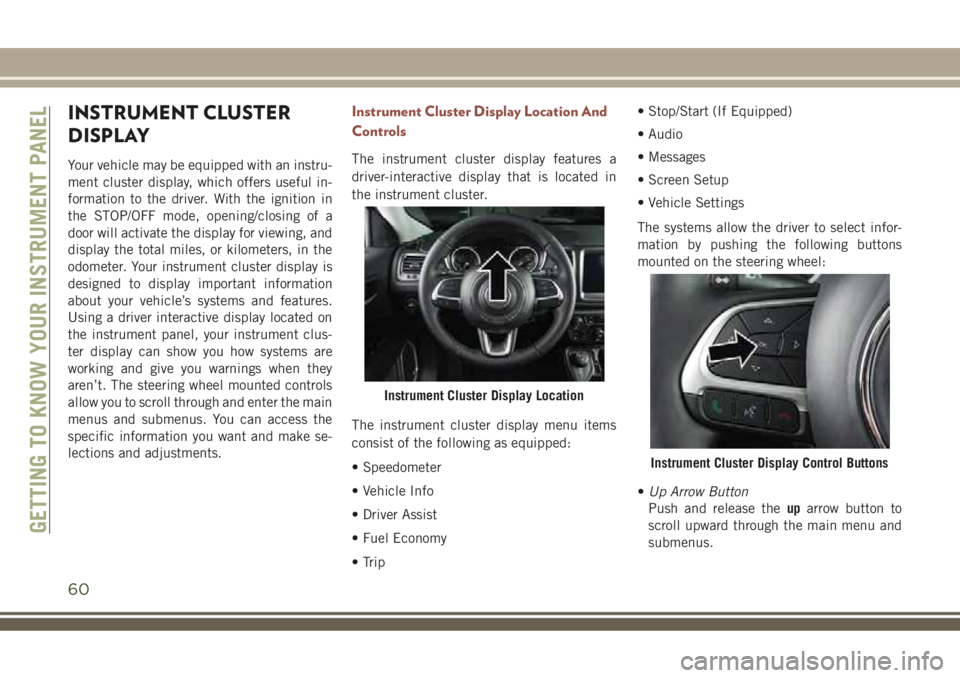
The instrument cluster display features a
driver-interactive display that is located in
the instrument cluster.
The instrument cluster display menu items
consist of the following as equipped:
• Speedometer
• Vehicle Info
• Driver Assist
• Fuel Economy
• Trip• Stop/Start (If Equipped)
• Audio
• Messages
• Screen Setup
• Vehicle Settings
The systems allow the driver to select infor-
mation by pushing the following buttons
mounted on the steering wheel:
•Up Arrow Button
Push and release theuparrow button to
scroll upward through the main menu and
submenus.
Instrument Cluster Display Location
Instrument Cluster Display Control Buttons
GETTING TO KNOW YOUR INSTRUMENT PANEL
60
Page 70 of 348
flash for approximately one minute and then
remain continuously illuminated. This se-
quence will continue upon subsequent ve-
hicle start-ups as long as the malfunction
exists. When the malfunction indicator is
illuminated, the system may not be able to
detect or signal low tire pressure as intended.
TPMS malfunctions may occur for a variety of
reasons, including the installation of replace-
ment or alternate tires or wheels on the ve-
hicle that prevent the TPMS from functioning
properly. Always check the TPMS malfunc-
tion telltale after replacing one or more tires
or wheels on your vehicle to ensure that the
replacement or alternate tires and wheels
allow the TPMS to continue to function
properly.
CAUTION!
The TPMS has been optimized for the
original equipment tires and wheels.
TPMS pressures and warning have been
established for the tire size equipped on
your vehicle. Undesirable system opera-
tion or sensor damage may result when
using replacement equipment that is not
CAUTION!
of the same size, type, and/or style. After-
market wheels can cause sensor damage.
Using aftermarket tire sealants may cause
the Tire Pressure Monitoring System
(TPMS) sensor to become inoperable. Af-
ter using an aftermarket tire sealant it is
recommended that you take your vehicle
to your authorized dealer to have your
sensor function checked.
— Towing Hook Breakdown Warning
Light — If Equipped
This light illuminates when there is a failure
with the tow hook. Contact your authorized
dealer for service.
— Vehicle Security Warning Light
This telltale will illuminate when the vehicle
security alarm system has detected an at-
tempt was made to break into the vehicle.
Yellow Indicator Lights
— 4WD Lock Indicator Light
This light alerts the driver that the vehicle is
in the four-wheel drive LOCK mode. The front
and rear driveshafts are mechanically locked
together, forcing the front and rear wheels to
rotate at the same speed.
Refer to “Four-Wheel Drive Operation” in
“Starting And Operating” for further informa-
tion on four-wheel drive operation and proper
use.
— 4WD Low Indicator Light — If
Equipped
This light alerts the driver that the vehicle is
in the four-wheel drive LOW mode. The front
and rear driveshafts are mechanically locked
together forcing the front and rear wheels to
rotate at the same speed. Low range provides
a greater gear reduction ratio to provide in-
creased torque at the wheels.
Refer to “Four-Wheel Drive Operation — If
Equipped” in “Starting And Operating” for
further information on four-wheel drive op-
eration and proper use.
GETTING TO KNOW YOUR INSTRUMENT PANEL
68
Page 71 of 348
— Wait To Start Light — If Equipped
The “Wait To Start” telltale will illuminate for
approximately two seconds when the ignition
is turned to the RUN position. Its duration
may be longer based on colder operating
conditions. Vehicle will not initiate start until
telltale is no longer displayed
. Refer to “Starting The Engine” in “Starting
And Operating” for further information.
NOTE:
The “Wait To Start” telltale may not illumi-
nate if the intake manifold temperature is
warm enough.
— Water In Fuel Indicator Light — If
Equipped
The “Water In Fuel Indicator Light” will illu-
minate when there is water detected in the
fuel filters. If this light remains on, DO NOT
start the vehicle before you drain the water
from the fuel filters to prevent engine dam-
age.
— Rear Fog Indicator — If Equipped
This indicator will illuminate when the rear
fog lights are on.
— Diesel Particulate Filter (DPF) Indi-
cator Light — If Equipped
When the light illuminates solid, the filter
loading is above the specified range.
— Forward Collision Indicator Light —
If Equipped
This telltale will turn on to warn you of a
possible collision with the vehicle in front of
you.
Forward Collision Warning Off Indicator
Light — If Equipped
This light indicates that Forward Collision
Warning is off.
— Active Speed Limiter Fault Indicator
Light — If Equipped
This light will turn on when there is a fault
detected with the Active Speed Limiter.
Green Indicator Lights
— Active Speed Limiter SET Indicator
Light
This light will turn on when the Active Speed
Limiter is on and set to a specific speed.
— Automatic High Beam Indicator
Light — If Equipped
This indicator shows that the automatic high
beam headlights are on.
— Front Fog Indicator Light — If
Equipped
This indicator will illuminate when the front
fog lights are on.
— Park/Headlight On Indicator Light
This indicator will illuminate when the park
lights or headlights are turned on.
— Speed Control SET Indicator Light
— If Equipped
This light will turn on when the speed control
is set. Refer to “Speed Control — If
Equipped” in “Starting And Operating” for
further information.
— Stop/Start Active Indicator Light —
If Equipped
This telltale will illuminate when the Stop/
Start function is in “Autostop” mode.
69
Page 78 of 348
SAFETY FEATURES
Anti-Lock Brake System (ABS)
The Anti-Lock Brake System (ABS) provides
increased vehicle stability and brake perfor-
mance under most braking conditions. The
system automatically prevents wheel lock,
and enhances vehicle control during braking.
The ABS performs a self-check cycle to en-
sure that the ABS is working properly each
time the vehicle is started and driven. During
this self-check, you may hear a slight clicking
sound as well as some related motor noises.
ABS is activated during braking when the
system detects one or more wheels begin to
lock. Road conditions such as ice, snow,
gravel, bumps, railroad tracks, loose debris,
or panic stops may increase the likelihood of
ABS activation(s).
You also may experience the following when
ABS activates:
• The ABS motor noise (it may continue to
run for a short time after the stop).
• The clicking sound of solenoid valves.• Brake pedal pulsations.
• A slight drop of the brake pedal at the end
of the stop.
These are all normal characteristics of ABS.
WARNING!
• The ABS contains sophisticated elec-
tronic equipment that may be suscep-
tible to interference caused by improp-
erly installed or high output radio
transmitting equipment. This interfer-
ence can cause possible loss of anti-lock
braking capability. Installation of such
equipment should be performed by
qualified professionals.
• Pumping of the Anti-Lock Brakes will
diminish their effectiveness and may
lead to a collision. Pumping makes the
stopping distance longer. Just press
firmly on your brake pedal when you
need to slow down or stop.
• The ABS cannot prevent the natural laws
of physics from acting on the vehicle,
nor can it increase braking or steering
efficiency beyond that afforded by the
WARNING!
condition of the vehicle brakes and tires
or the traction afforded.
• The ABS cannot prevent collisions, in-
cluding those resulting from excessive
speed in turns, following another vehicle
too closely, or hydroplaning.
• The capabilities of an ABS equipped
vehicle must never be exploited in a
reckless or dangerous manner that could
jeopardize the user’s safety or the safety
of others.
ABS is designed to function with the OEM
tires. Modification may result in degraded
ABS performance.
Anti-Lock Brake Warning Light
The yellow “Anti-Lock Brake Warning Light”
will turn on when the ignition is turned to the
ON/RUN mode and may stay on for as long as
four seconds.
If the “Anti-Lock Brake Warning Light” re-
mains on or comes on while driving, it indi-
cates that the anti-lock portion of the brake
system is not functioning and that service is
SAFETY
76
Page 80 of 348
Brake System Warning Light
The red “Brake System Warning Light” will
turn on when the ignition is turned to the
ON/RUN mode and may stay on for as long as
four seconds.
If the “Brake System Warning Light” remains
on or comes on while driving, it indicates that
the brake system is not functioning properly
and that immediate service is required. If the
“Brake System Warning Light” does not
come on when the ignition is turned to the
ON/RUN mode, have the light repaired as
soon as possible.
Dynamic Steering Torque (DST)
Dynamic Steering Torque is a feature of the
ESC and Electric Power Steering (EPS) mod-
ules that provides torque at the steering
wheel for certain driving conditions in which
the ESC module is detecting vehicle instabil-
ity. The torque that the steering wheel re-
ceives is only meant to help the driver realize
optimal steering behavior in order to reach/maintain vehicle stability. The only notifica-
tion the driver receives that the feature is
active is the torque applied to the steering
wheel.
NOTE:
The DST feature is only meant to help the
driver realize the correct course of action
through small torques on the steering wheel,
which means the effectiveness of the DST
feature is highly dependent on the driver’s
sensitivity and overall reaction to the applied
torque. It is very important to realize that this
feature will not steer the vehicle, meaning
the driver is still responsible for steering the
vehicle.Electronic Brake Force Distribution (EBD)
This function manages the distribution of the
braking torque between the front and rear
axles by limiting braking pressure to the rear
axle. This is done to prevent overslip of the
rear wheels to avoid vehicle instability, and to
prevent the rear axle from entering ABS be-
fore the front axle.
Electronic Roll Mitigation (ERM)
This system anticipates the potential for
wheel lift by monitoring the driver’s steering
wheel input and the speed of the vehicle.
When ERM determines that the rate of
change of the steering wheel angle and vehi-
cle’s speed are sufficient to potentially cause
wheel lift, it then applies the appropriate
brake and may also reduce engine power to
lessen the chance that wheel lift will occur.
ERM can only reduce the chance of wheel lift
occurring during severe or evasive driving
maneuvers; it cannot prevent wheel lift due
to other factors, such as road conditions,
leaving the roadway, or striking objects or
other vehicles.
WARNING!
Many factors, such as vehicle loading,
road conditions and driving conditions,
influence the chance that wheel lift or
rollover may occur. ERM cannot prevent
all wheel lift or roll overs, especially those
that involve leaving the roadway or striking
objects or other vehicles. The capabilities
SAFETY
78