ECO mode JEEP COMPASS 2018 Owner handbook (in English)
[x] Cancel search | Manufacturer: JEEP, Model Year: 2018, Model line: COMPASS, Model: JEEP COMPASS 2018Pages: 348, PDF Size: 6.03 MB
Page 82 of 348
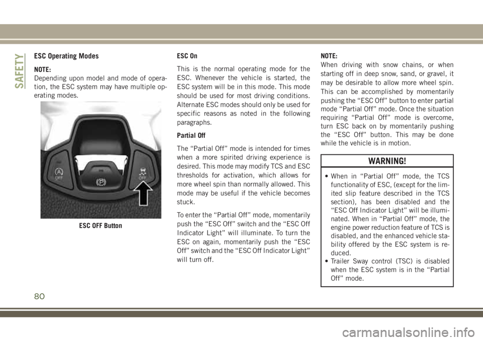
ESC Operating Modes
NOTE:
Depending upon model and mode of opera-
tion, the ESC system may have multiple op-
erating modes.ESC On
This is the normal operating mode for the
ESC. Whenever the vehicle is started, the
ESC system will be in this mode. This mode
should be used for most driving conditions.
Alternate ESC modes should only be used for
specific reasons as noted in the following
paragraphs.
Partial Off
The “Partial Off” mode is intended for times
when a more spirited driving experience is
desired. This mode may modify TCS and ESC
thresholds for activation, which allows for
more wheel spin than normally allowed. This
mode may be useful if the vehicle becomes
stuck.
To enter the “Partial Off” mode, momentarily
push the “ESC Off” switch and the “ESC Off
Indicator Light” will illuminate. To turn the
ESC on again, momentarily push the “ESC
Off” switch and the “ESC Off Indicator Light”
will turn off.NOTE:
When driving with snow chains, or when
starting off in deep snow, sand, or gravel, it
may be desirable to allow more wheel spin.
This can be accomplished by momentarily
pushing the “ESC Off” button to enter partial
mode “Partial Off” mode. Once the situation
requiring “Partial Off” mode is overcome,
turn ESC back on by momentarily pushing
the “ESC Off” button. This may be done
while the vehicle is in motion.
WARNING!
• When in “Partial Off” mode, the TCS
functionality of ESC, (except for the lim-
ited slip feature described in the TCS
section), has been disabled and the
“ESC Off Indicator Light” will be illumi-
nated. When in “Partial Off” mode, the
engine power reduction feature of TCS is
disabled, and the enhanced vehicle sta-
bility offered by the ESC system is re-
duced.
• Trailer Sway control (TSC) is disabled
when the ESC system is in the “Partial
Off” mode.
ESC OFF Button
SAFETY
80
Page 83 of 348
Full Off (Four-Wheel Drive Models Only)
This mode is intended for off-highway or
off-road use when ESC stability features
could inhibit vehicle maneuverability due to
trail conditions. This mode is entered by
pushing and holding the “ESC Off” switch for
five seconds when the vehicle is stopped and
the engine is running. After five seconds, the
"ESC OFF Indicator Light" will illuminate and
the “ESC OFF” message will appear in the
instrument cluster display.
In this mode, ESC and TCS, except for the
“limited slip” feature described in the TCS
section, are turned off until the vehicle
reaches a speed of 40 mph (64 km/h). At
40 mph (64 km/h), the system returns to
“Partial Off” mode, as described above. TCS
remains off. When the vehicle speed drops
below 30 mph (48 km/h), the ESC system
shuts off. ESC is deactivated at low vehicle
speeds so that it will not interfere with off-
road driving however, ESC function returns to
provide the stability feature at speeds above
40 mph (64 km/h). The "ESC OFF Indicator
Light" will always be illuminated when ESC is
off.To turn ESC on again, momentarily push the
“ESC Off” switch. This will restore the “ESC
On” mode of operation.
NOTE:
The “ESC OFF” message will display and an
audible chime will sound when the gear se-
lector is placed into the PARK position from
any other position, and then moved out of the
PARK position. This will occur even if the
message was previously cleared.
WARNING!
In the "Full Off" mode, the engine torque
reduction and stability features are disabled.
In an emergency evasive maneuver, the ESC
system will not engage to assist in maintain-
ing stability. “ESC Off” mode is intended for
off-highway or off-road use only.
ESC Activation/Malfunction Indicator Light
And ESC OFF Indicator Light
The “ESC Activation/
Malfunction Indicator Light” in
the instrument cluster will come
on when the ignition is turned tothe ON mode. It should go out with the
engine running. If the “ESC Activation/
Malfunction Indicator Light” comes on con-
tinuously with the engine running, a malfunc-
tion has been detected in the ESC system. If
this light remains on after several ignition
cycles, and the vehicle has been driven sev-
eral miles (kilometers) at speeds greater than
30 mph (48 km/h), see your authorized
dealer as soon as possible to have the prob-
lem diagnosed and corrected.
The “ESC Activation/Malfunction Indicator
Light” (located in the instrument cluster)
starts to flash as soon as the tires lose trac-
tion and the ESC system becomes active. The
“ESC Activation/Malfunction Indicator
Light” also flashes when TCS is active. If the
“ESC Activation/Malfunction Indicator
Light” begins to flash during acceleration,
ease up on the accelerator and apply as little
throttle as possible. Be sure to adapt your
speed and driving to the prevailing road con-
ditions.
81
Page 84 of 348
NOTE:
• The “ESC Activation/Malfunction Indicator
Light” and the “ESC OFF Indicator Light”
come on momentarily each time the igni-
tion is turned ON.
• Each time the ignition is turned ON, the
ESC system will be on even if it was turned
off previously.
• The ESC system will make buzzing or click-
ing sounds when it is active. This is normal;
the sounds will stop when ESC becomes
inactive following the maneuver that
caused the ESC activation.
The “ESC OFF Indicator Light”
indicates the customer has
elected to have the Electronic
Stability Control (ESC) in a re-
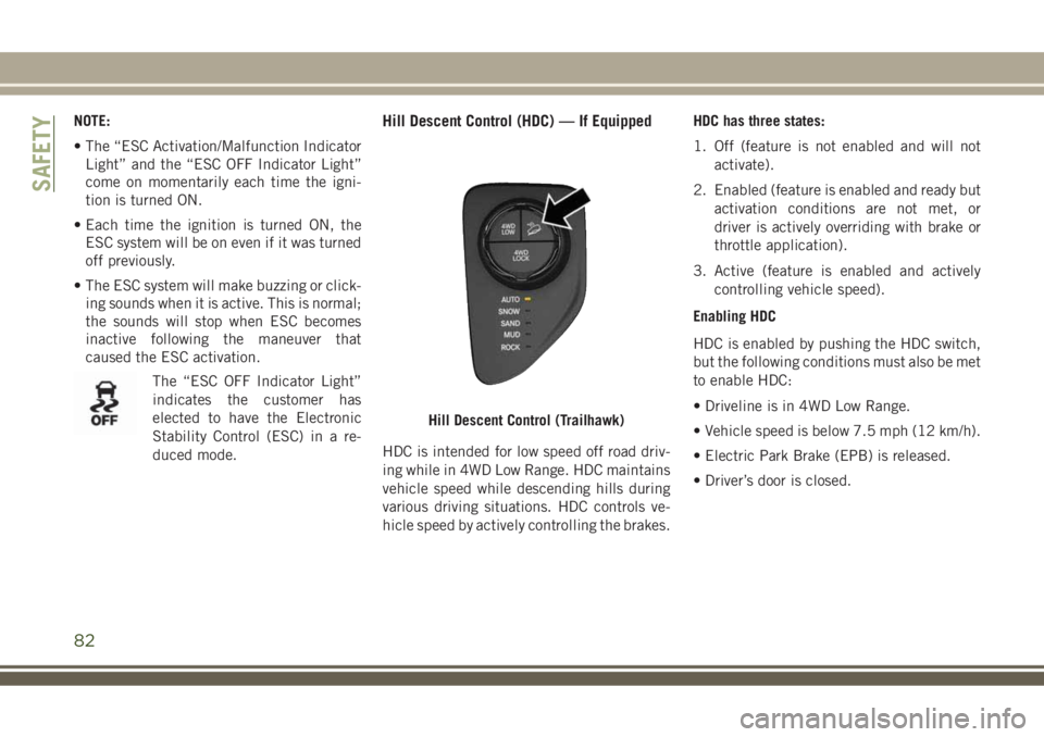
duced mode.Hill Descent Control (HDC) — If Equipped
HDC is intended for low speed off road driv-
ing while in 4WD Low Range. HDC maintains
vehicle speed while descending hills during
various driving situations. HDC controls ve-
hicle speed by actively controlling the brakes.HDC has three states:
1. Off (feature is not enabled and will not
activate).
2. Enabled (feature is enabled and ready but
activation conditions are not met, or
driver is actively overriding with brake or
throttle application).
3. Active (feature is enabled and actively
controlling vehicle speed).
Enabling HDC
HDC is enabled by pushing the HDC switch,
but the following conditions must also be met
to enable HDC:
• Driveline is in 4WD Low Range.
• Vehicle speed is below 7.5 mph (12 km/h).
• Electric Park Brake (EPB) is released.
• Driver’s door is closed.
Hill Descent Control (Trailhawk)
SAFETY
82
Page 87 of 348
Rain Brake Support (RBS)
Rain Brake Support may improve braking
performance in wet conditions. It will periodi-
cally apply a small amount of brake pressure
to remove any water buildup on the front
brake rotors. It functions when the wind-
shield wipers are in LO or HI speed. When
Rain Brake Support is active, there is no
notification to the driver and no driver inter-
action is required.
Ready Alert Braking (RAB)
Ready Alert Braking may reduce the time
required to reach full braking during emer-
gency braking situations. It anticipates when
an emergency braking situation may occur by
monitoring how fast the throttle is released by
the driver. The EBC will prepare the brake
system for a panic stop.
Trailer Sway Control (TSC)
TSC uses sensors in the vehicle to recognize
an excessively swaying trailer and will take
the appropriate actions to attempt to stop the
sway. TSC will become active automatically
once an excessively swaying trailer is recog-
nized.NOTE:
TSC cannot stop all trailers from swaying.
Always use caution when towing a trailer and
follow the trailer tongue weight recommenda-
tions. Refer to “Trailer Towing” in “Starting
And Operating” for further information.
When TSC is functioning, the “ESC
Activation/Malfunction Indicator Light” will
flash, the engine power may be reduced and
you may feel the brakes being applied to
individual wheels to attempt to stop the
trailer from swaying. TSC is disabled when
the ESC system is in the “Partial Off” or “Full
Off” modes.
WARNING!
If TSC activates while driving, slow the
vehicle down, stop at the nearest safe
location, and adjust the trailer load to
eliminate trailer sway.
AUXILIARY DRIVING
SYSTEMS
Blind Spot Monitoring (BSM) — If
Equipped
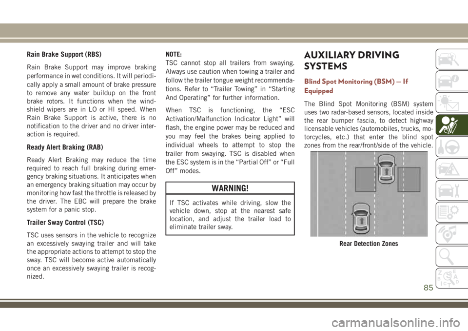
The Blind Spot Monitoring (BSM) system
uses two radar-based sensors, located inside
the rear bumper fascia, to detect highway
licensable vehicles (automobiles, trucks, mo-
torcycles, etc.) that enter the blind spot
zones from the rear/front/side of the vehicle.
Rear Detection Zones
85
Page 107 of 348
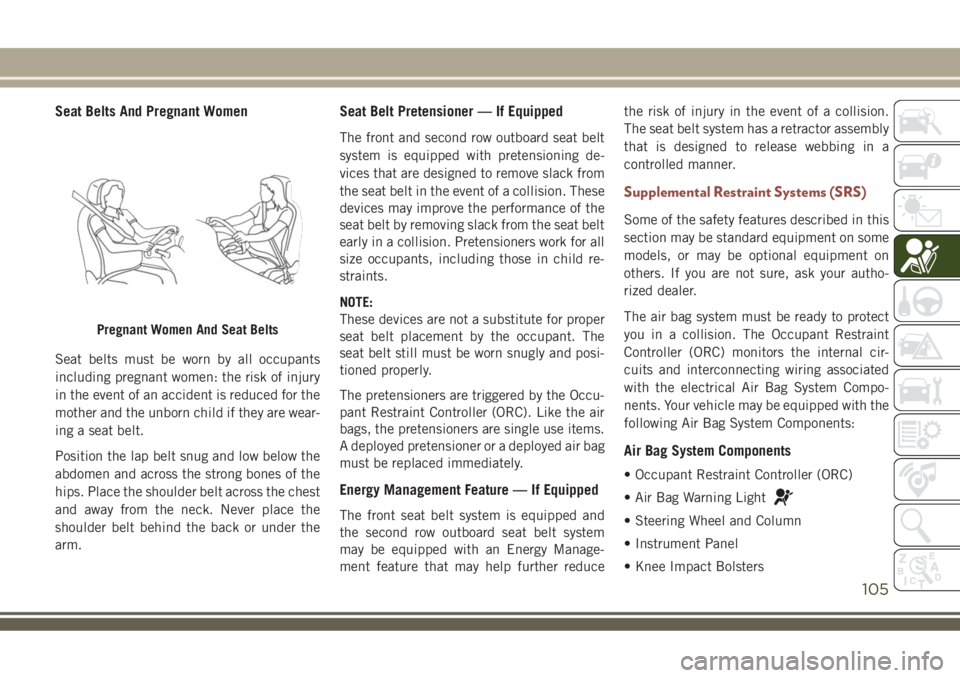
Seat Belts And Pregnant Women
Seat belts must be worn by all occupants
including pregnant women: the risk of injury
in the event of an accident is reduced for the
mother and the unborn child if they are wear-
ing a seat belt.
Position the lap belt snug and low below the
abdomen and across the strong bones of the
hips. Place the shoulder belt across the chest
and away from the neck. Never place the
shoulder belt behind the back or under the
arm.
Seat Belt Pretensioner — If Equipped
The front and second row outboard seat belt
system is equipped with pretensioning de-
vices that are designed to remove slack from
the seat belt in the event of a collision. These
devices may improve the performance of the
seat belt by removing slack from the seat belt
early in a collision. Pretensioners work for all
size occupants, including those in child re-
straints.
NOTE:
These devices are not a substitute for proper
seat belt placement by the occupant. The
seat belt still must be worn snugly and posi-
tioned properly.
The pretensioners are triggered by the Occu-
pant Restraint Controller (ORC). Like the air
bags, the pretensioners are single use items.
A deployed pretensioner or a deployed air bag
must be replaced immediately.
Energy Management Feature — If Equipped
The front seat belt system is equipped and
the second row outboard seat belt system
may be equipped with an Energy Manage-
ment feature that may help further reducethe risk of injury in the event of a collision.
The seat belt system has a retractor assembly
that is designed to release webbing in a
controlled manner.
Supplemental Restraint Systems (SRS)
Some of the safety features described in this
section may be standard equipment on some
models, or may be optional equipment on
others. If you are not sure, ask your autho-
rized dealer.
The air bag system must be ready to protect
you in a collision. The Occupant Restraint
Controller (ORC) monitors the internal cir-
cuits and interconnecting wiring associated
with the electrical Air Bag System Compo-
nents. Your vehicle may be equipped with the
following Air Bag System Components:
Air Bag System Components
• Occupant Restraint Controller (ORC)
• Air Bag Warning Light
• Steering Wheel and Column
• Instrument Panel
• Knee Impact Bolsters
Pregnant Women And Seat Belts
105
Page 139 of 348
Safety Checks You Should Make Inside
The Vehicle
Seat Belts
Inspect the seat belt system periodically,
checking for cuts, frays, and loose parts.
Damaged parts must be replaced immedi-
ately. Do not disassemble or modify the sys-
tem.
Front seat belt assemblies must be replaced
after a collision. Rear seat belt assemblies
must be replaced after a collision if they have
been damaged (i.e., bent retractor, torn web-
bing, etc.). If there is any question regarding
seat belt or retractor condition, replace the
seat belt.
Air Bag Warning Light
The Air Bag warning lightwill turn on for
four to eight seconds as a bulb check when
the ignition switch is first turned to ON/RUN.
If the light is either not on during starting,
stays on, or turns on while driving, have the
system inspected at your authorized dealer as
soon as possible. After the bulb check, this
light will illuminate with a single chime whena fault with the Air Bag System has been
detected. It will stay on until the fault is
removed. If the light comes on intermittently
or remains on while driving, have your autho-
rized dealer service the vehicle immediately.
Refer to “Occupant Restraint Systems” in
“Safety” for further information.
Defroster
Check operation by selecting the defrost
mode and place the blower control on high
speed. You should be able to feel the air
directed against the windshield. See your
authorized dealer for service if your defroster
is inoperable.
Floor Mat Safety Information
Always use floor mats designed to fit your
vehicle. Only use a floor mat that does not
interfere with the operation of the accelera-
tor, brake or clutch pedals. Only use a floor
mat that is securely attached using the floor
mat fasteners so it cannot slip out of position
and interfere with the accelerator, brake or
clutch pedals or impair safe operation of your
vehicle in other ways.
WARNING!
An improperly attached, damaged, folded,
or stacked floor mat, or damaged floor mat
fasteners may cause your floor mat to in-
terfere with the accelerator, brake, or
clutch pedals and cause a loss of vehicle
control. To prevent SERIOUS INJURY or
DEATH:
• ALWAYS securely attach
your floor
mat using the floor mat fasteners. DO
NOT install your floor mat upside down
or turn your floor mat over. Lightly pull to
confirm mat is secured using the floor
mat fasteners on a regular basis.
• ALWAYS REMOVE THE EXISTING
FLOOR MAT FROM THE VEHICLE
before installing any other floor mat.
NEVER install or stack an additional
floor mat on top of an existing floor mat.
• ONLY install floor mats designed to fit
your vehicle. NEVER install a floor mat
that cannot be properly attached and
secured to your vehicle. If a floor mat
needs to be replaced, only use a FCA
approved floor mat for the specific
make, model, and year of your vehicle.
137
Page 143 of 348
STARTING THE ENGINE
Before starting your vehicle, adjust your seat,
adjust both inside and outside mirrors, and
fasten your seat belts.
WARNING!
• When exiting the vehicle, always remove
the key fob from the vehicle and lock
your vehicle.
• Never leave children alone in a vehicle,
or with access to an unlocked vehicle.
• Allowing children to be in a vehicle un-
attended is dangerous for a number of
reasons. A child or others could be seri-
ously or fatally injured. Children should
be warned not to touch the parking
brake, brake pedal or the transmission
gear selector.
• Do not leave the key fob in or near the
vehicle, or in a location accessible to
children, and do not leave the ignition of
a vehicle equipped with Keyless Enter-
N-Go in the ACC or ON/RUN mode. A
child could operate power windows,
other controls, or move the vehicle.
WARNING!
• Do not leave children or animals inside
parked vehicles in hot weather. Interior
heat build-up may cause serious injury
or death.
Start the engine with the gear selector in the
NEUTRAL or PARK position. Apply the brake
before shifting to any driving range.
Normal Starting — Gasoline Engine
NOTE:
Normal starting of either a cold or a warm
engine is obtained without pumping or press-
ing the accelerator pedal.
Cycle the ignition switch to the START posi-
tion and release when the engine starts. If the
engine fails to start within 10 seconds, cycle
the ignition switch to the LOCK/OFF position,
wait 10 to 15 seconds, then repeat the “Nor-
mal Starting” procedure.
Tip Start Feature
Cycle the ignition switch to START position
and release it as soon as the starter engages.
The starter motor will continue to run, andwill automatically disengage itself when the
engine is running. If the engine fails to start,
cycle the ignition switch to the OFF position,
wait 10 to 15 seconds, then repeat the “Nor-
mal Starting” procedure.
Automatic Transmission
The gear selector must be in the NEUTRAL or
PARK position before you can start the en-
gine. Apply the brakes before shifting into
any driving gear.
CAUTION!
Damage to the transmission may occur if
the following precautions are not ob-
served:
• Do not shift between PARK, REVERSE,
NEUTRAL, or DRIVE when the engine is
above idle speed.
• Shift into or out of PARK or REVERSE
only after the vehicle has come to a
complete stop.
• Before shifting into any gear, make sure
your foot is firmly on the brake pedal.
141
Page 144 of 348
Keyless Ignition Functions — Using The ENGINE
START/STOP Button
1. The transmission must be in PARK or
NEUTRAL.
2. Press and hold the brake pedal while
pushing the ENGINE START/STOP button
once.
3. The system takes over and attempts to
start the vehicle. If the vehicle fails to
start, the starter will disengage automati-
cally after 10 seconds.
4. If you wish to stop the cranking of the
engine prior to the engine starting, push
the button again.
NOTE:
Normal starting of either a cold or a warm
engine is obtained without pumping or press-
ing the accelerator pedal.
Keyless Ignition Functions — With Driver’s Foot
OFF The Brake Pedal/Clutch Pedal (In PARK Or
NEUTRAL Position)
The Keyless Ignition feature operates similar to
an ignition switch. It has three modes, OFF,
ON/RUN, and START. To change the ignitionmodes without starting the vehicle and use the
accessories follow these steps starting with the
ignition switch in the OFF mode:
1. Push the ENGINE START/STOP button
once to change the ignition switch to the
ON/RUN mode.
2. Push the ENGINE START/STOP button a
second time to change the ignition switch
to the OFF mode.
Manual Transmission
The gear selector must be in the NEUTRAL
position before you can start the engine.
Apply the brakes before shifting into any
driving gear.
Keyless Ignition Functions — Using The ENGINE
START/STOP Button
1. The transmission must be in NEUTRAL.
2. Press and hold the clutch pedal while
pushing the ENGINE START/STOP button
once.
3. The system takes over and attempts to
start the vehicle. If the vehicle fails to
start, the starter will disengage automati-
cally after 10 seconds.4. If you wish to stop the cranking of the
engine prior to the engine starting, push
the button again.
NOTE:
Normal starting of either a cold or a warm
engine is obtained without pumping or press-
ing the accelerator pedal.
Keyless Ignition Functions — With Driver’s Foot
OFF The Brake Pedal/Clutch Pedal (In PARK Or
NEUTRAL Position)
The Keyless Ignition feature operates similar
to an ignition switch. It has three modes,
OFF, ON/RUN, and START. To change the
ignition modes without starting the vehicle
and use the accessories follow these steps
starting with the ignition switch in the OFF
position:
1. Push the ENGINE START/STOP button
once to change the ignition to the ON/
RUN mode.
2. Push the ENGINE START/STOP button a
second time to change the ignition switch
to the OFF mode.
STARTING AND OPERATING
142
Page 145 of 348
Stopping The Engine
Vehicles Equipped With A Mechanical Key Fob:
To turn off the engine, proceed as follows:
1. Park the car in a position that does not
cause a traffic hazard.
2. Place the transmission in gear (models
with a manual transmission) or place the
transmission in PARK (P) (models with
automatic transmission).
3. With the engine idling, place the ignition
in the STOP/OFF position.
4. Remove the key from the ignition when
the engine is shut off.
Vehicles Equipped With Electronic Key (Keyless
Ignition):
To shut off the engine with vehicle speed
greater than 5 mph (8 km/h), you must push
and hold the ignition or push the START/
STOP button three times consecutively
within a few seconds. The engine will shut
down, and the ignition will be placed in the
RUN position.Turning Off the car (placing the ignition from
the RUN position to the STOP position), the
power supply to the accessories are main-
tained for a period of three minutes.
Opening the driver side door with the ignition
in RUN will sound a short chime that reminds
the driver to place the ignition to STOP.
When the ignition is in the STOP/OFF posi-
tion, the window switches remains active for
three minutes. Opening a front door will can-
cel this function.
After severe driving, idle the engine to allow
the temperature inside the engine compart-
ment to cool before shutting off the engine.
Normal Starting — Diesel Engine
Before starting your vehicle, adjust your seat,
both inside and outside mirrors, and fasten
your seat belts.
The starter is allowed to crank for up to
30-second intervals. Waiting a few minutes
between such intervals will protect the starter
from overheating.
WARNING!
• Before exiting a vehicle, always come to
a complete stop, then shift the auto-
matic transmission into PARK and apply
the parking brake.
• Always make sure the keyless ignition
node is in the OFF mode, key fob is
removed from the vehicle and vehicle is
locked.
• Never leave children alone in a vehicle,
or with access to an unlocked vehicle.
Leaving children in a vehicle unattended
is dangerous for a number of reasons. A
child or others could be seriously or
fatally injured. Children should be
warned not to touch the parking brake,
brake pedal or the gear selector.
• Do not leave the key fob in or near the
vehicle, or in a location accessible to
children, and do not leave the ignition of
a vehicle equipped with Keyless Enter-
N-Go in the ACC or ON/RUN mode. A
child could operate power windows,
other controls, or move the vehicle.
143
Page 153 of 348
WARNING!
Allowing children to be in a vehicle un-
attended is dangerous for a number of
reasons. A child or others could be seri-
ously or fatally injured. Children should
be warned not to touch the park brake,
brake pedal or the transmission gear
selector.
• Do not leave the key fob in or near the
vehicle (or in a location accessible to
children), and do not leave the ignition
(in a vehicle equipped with push button
start) in the ON/RUN mode. A child
could operate power windows, other
controls, or move the vehicle.
CAUTION!
Damage to the transmission may occur if
the following precautions are not ob-
served:
• Shift into or out of PARK or REVERSE
only after the vehicle has come to a
complete stop.
CAUTION!
• Do not shift between PARK, REVERSE,
NEUTRAL, or DRIVE when the engine is
above idle speed.
• Before shifting into any gear, make sure
your foot is firmly pressing the brake
pedal.
NOTE:
You must press and hold the brake pedal
while shifting out of PARK.
Ignition Park Interlock
Vehicles with push button start:
This vehicle is equipped with an Ignition Park
Interlock which requires the transmission to
be in PARK before the ignition can be turned
to the OFF mode. This helps the driver avoid
inadvertently leaving the vehicle without
placing the transmission in PARK. This sys-
tem also locks the transmission in PARK
whenever the ignition is in the OFF mode.Vehicles with mechanical key:
This vehicle is equipped with a Key Ignition
Park Interlock which requires the transmis-
sion to be in PARK before the ignition can be
turned to the OFF (key removal) position. The
key can only be removed from the ignition
when the ignition is in the OFF position, and
the transmission is locked in PARK whenever
the ignition is in the OFF position.
If the vehicle's battery becomes discharged,
the key will be trapped in the ignition even
when the gear selector is in PARK. Recharge
the battery to allow key removal.Brake/Transmission Shift Interlock
System
This vehicle is equipped with a Brake Trans-
mission Shift Interlock system (BTSI) that
holds the transmission gear selector in PARK
unless the brakes are applied. To shift the
transmission out of PARK, the ignition must
be in the ON/RUN mode (whether the engine
is running or not), and the brake pedal must
be pressed. The brake pedal must also be
pressed to shift from NEUTRAL into DRIVE or
REVERSE when the vehicle is stopped or
moving at low speeds.
151