ignition JEEP COMPASS 2018 Owner handbook (in English)
[x] Cancel search | Manufacturer: JEEP, Model Year: 2018, Model line: COMPASS, Model: JEEP COMPASS 2018Pages: 348, PDF Size: 6.03 MB
Page 24 of 348
To Disarm The System
The vehicle security alarm can be disarmed
using any of the following methods:
• Push the unlock button on the key fob.
• Grasp the passive entry door handle to
unlock the door, refer to "Doors" in "Getting
To Know Your Vehicle" in your Owner’s
Manual for further information).
• Cycle the vehicle ignition system out of the
OFF position.
– For vehicles equipped with Keyless
Enter-N-Go — Passive Entry, push the
Start/Stop ignition button (requires at
least one valid key fob in the vehicle).
– For vehicles not equipped with Keyless
Enter-N-Go — Passive Entry, insert a
valid Integrated Vehicle Key into the
ignition switch and turn the key to the
ON position.
NOTE:
• The driver's door key cylinder and the lift-
gate button on the key fob cannot arm or
disarm the vehicle security alarm.
• The vehicle security alarm remains armed
during power liftgate entry. Pushing theliftgate button will not disarm the vehicle
security alarm. If someone enters the ve-
hicle through the liftgate and opens any
door the alarm will sound.
• When the vehicle security alarm is armed,
the interior power door lock switches will
not unlock the doors.
• The ultrasonic intrusion sensor (motion de-
tector) actively monitors your vehicle every
time you arm the security system. If you
prefer, you can turn off the ultrasonic intru-
sion sensor when arming the security sys-
tem. To do so, push the lock button on the
key fob five times within five seconds of
arming the system (while the vehicle secu-
rity light is flashing rapidly).
The vehicle security alarm is designed to
protect your vehicle; however, you can create
conditions where the system will give you a
false alarm. If one of the previously described
arming sequences has occurred, the vehicle
security alarm will arm regardless of whether
you are in the vehicle or not. If you remain in
the vehicle and open a door, the alarm will
sound. If this occurs, disarm the vehicle
security alarm.If the vehicle security alarm is armed and the
battery becomes disconnected, the vehicle
security alarm will remain armed when the
battery is reconnected; the exterior lights will
flash, the horn will sound. If this occurs,
disarm the vehicle security alarm.
Security System Manual Override
The system will not arm if you lock the doors
using the manual door lock plunger.
DOORS
Keyless Enter-N-Go — Passive Entry
The Passive Entry system is an enhancement
to the vehicle’s Remote Keyless Entry system
and a feature of Keyless Enter-N-Go — Pas-
sive Entry. This feature allows you to lock and
unlock the vehicle’s door(s) and fuel door
without having to push the key fob lock or
unlock buttons.
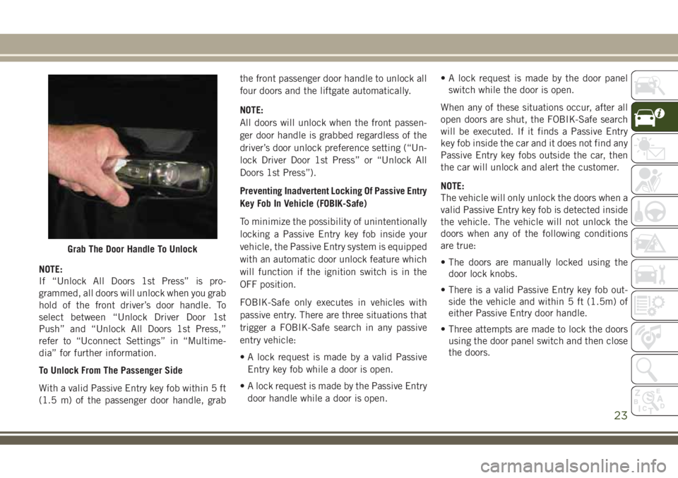
To Unlock From The Driver's Side
With a valid Passive Entry key fob within 5 ft
(1.5 m) of the driver's door handle, grab the
front driver door handle to unlock the driver's
door automatically.
GETTING TO KNOW YOUR VEHICLE
22
Page 25 of 348
NOTE:
If “Unlock All Doors 1st Press” is pro-
grammed, all doors will unlock when you grab
hold of the front driver’s door handle. To
select between “Unlock Driver Door 1st
Push” and “Unlock All Doors 1st Press,”
refer to “Uconnect Settings” in “Multime-
dia” for further information.
To Unlock From The Passenger Side
With a valid Passive Entry key fob within 5 ft
(1.5 m) of the passenger door handle, grabthe front passenger door handle to unlock all
four doors and the liftgate automatically.
NOTE:
All doors will unlock when the front passen-
ger door handle is grabbed regardless of the
driver’s door unlock preference setting (“Un-
lock Driver Door 1st Press” or “Unlock All
Doors 1st Press”).
Preventing Inadvertent Locking Of Passive Entry
Key Fob In Vehicle (FOBIK-Safe)
To minimize the possibility of unintentionally
locking a Passive Entry key fob inside your
vehicle, the Passive Entry system is equipped
with an automatic door unlock feature which
will function if the ignition switch is in the
OFF position.
FOBIK-Safe only executes in vehicles with
passive entry. There are three situations that
trigger a FOBIK-Safe search in any passive
entry vehicle:
• A lock request is made by a valid Passive
Entry key fob while a door is open.
• A lock request is made by the Passive Entry
door handle while a door is open.• A lock request is made by the door panel
switch while the door is open.
When any of these situations occur, after all
open doors are shut, the FOBIK-Safe search
will be executed. If it finds a Passive Entry
key fob inside the car and it does not find any
Passive Entry key fobs outside the car, then
the car will unlock and alert the customer.
NOTE:
The vehicle will only unlock the doors when a
valid Passive Entry key fob is detected inside
the vehicle. The vehicle will not unlock the
doors when any of the following conditions
are true:
• The doors are manually locked using the
door lock knobs.
• There is a valid Passive Entry key fob out-
side the vehicle and within 5 ft (1.5m) of
either Passive Entry door handle.
• Three attempts are made to lock the doors
using the door panel switch and then close
the doors.
Grab The Door Handle To Unlock
23
Page 28 of 348
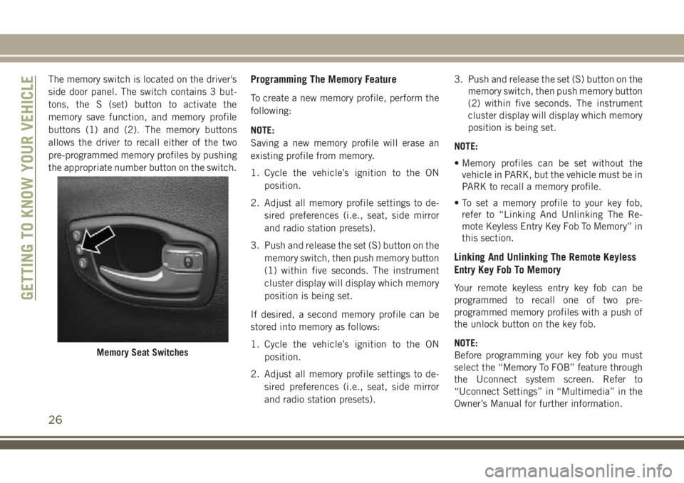
The memory switch is located on the driver's
side door panel. The switch contains 3 but-
tons, the S (set) button to activate the
memory save function, and memory profile
buttons (1) and (2). The memory buttons
allows the driver to recall either of the two
pre-programmed memory profiles by pushing
the appropriate number button on the switch.Programming The Memory Feature
To create a new memory profile, perform the
following:
NOTE:
Saving a new memory profile will erase an
existing profile from memory.
1. Cycle the vehicle’s ignition to the ON
position.
2. Adjust all memory profile settings to de-
sired preferences (i.e., seat, side mirror
and radio station presets).
3. Push and release the set (S) button on the
memory switch, then push memory button
(1) within five seconds. The instrument
cluster display will display which memory
position is being set.
If desired, a second memory profile can be
stored into memory as follows:
1. Cycle the vehicle’s ignition to the ON
position.
2. Adjust all memory profile settings to de-
sired preferences (i.e., seat, side mirror
and radio station presets).3. Push and release the set (S) button on the
memory switch, then push memory button
(2) within five seconds. The instrument
cluster display will display which memory
position is being set.
NOTE:
• Memory profiles can be set without the
vehicle in PARK, but the vehicle must be in
PARK to recall a memory profile.
• To set a memory profile to your key fob,
refer to “Linking And Unlinking The Re-
mote Keyless Entry Key Fob To Memory” in
this section.
Linking And Unlinking The Remote Keyless
Entry Key Fob To Memory
Your remote keyless entry key fob can be
programmed to recall one of two pre-
programmed memory profiles with a push of
the unlock button on the key fob.
NOTE:
Before programming your key fob you must
select the “Memory To FOB” feature through
the Uconnect system screen. Refer to
“Uconnect Settings” in “Multimedia” in the
Owner’s Manual for further information.
Memory Seat Switches
GETTING TO KNOW YOUR VEHICLE
26
Page 29 of 348
To program your key fob, perform the follow-
ing:
1. Cycle the vehicle’s ignition to the OFF
position.
2. Select the desired memory profile (1) or
(2).
NOTE:
If a memory profile has not already been
set, refer to "Programming The Memory
Feature" in this section for instructions on
how to set a memory profile.
3. Push and release the set (S) button on the
memory switch, then within five seconds
push and release the button labeled (1) or
(2) accordingly. “Memory Profile Set”
(1 or 2) will display in the instrument
cluster display.
4. Push and release the lock button on the
key fob within 10 seconds.
NOTE:
Your key fob can be unlinked to your memory
settings by pushing the set (S) button, fol-
lowed by pushing the unlock button on the
key fob within 10 seconds.Memory Position Recall
NOTE:
The vehicle must be in PARK to recall
memory positions. If a recall is attempted
when the vehicle is not in PARK, a message
will display in the instrument cluster display.
• To recall the memory settings for driver one,
push memory button (1) or the unlock but-
ton on the key fob linked to memory posi-
tion 1.
• To recall the memory settings for driver two,
push memory button (2) or the unlock but-
ton on the key fob linked to memory posi-
tion 2.
A recall can be canceled by pushing any of
the memory buttons (S, 1, or 2) during a
recall. When a recall is canceled, the driver
seat will stop moving. A delay of one second
will occur before another recall can be se-
lected.
Easy Entry/Exit Seat
This feature provides automatic driver seat
positioning to enhance driver mobility when
entering and exiting the vehicle.The distance the driver seat moves depends
on where you have the driver seat positioned
when you cycle the vehicle’s ignition to the
OFF position.
• When you cycle the vehicle’s ignition to the
OFF position, the driver seat will move
about 2.4 inches (60 mm) rearward if the
driver seat position is greater than or equal
to 2.7 inches (67.7 mm) forward of the rear
stop. The seat will return to its previously
set position when you cycle the vehicle’s
ignition to the ACC or RUN position.
• The Easy Entry/Easy Exit feature is disabled
when the driver seat position is less than
0.9 of an inch (22.7 mm) forward of the
rear stop. At this position, there is no ben-
efit to the driver by moving the seat for Easy
Exit or Easy Entry.
Each stored memory setting will have an
associated Easy Entry and Easy Exit position.
27
Page 37 of 348
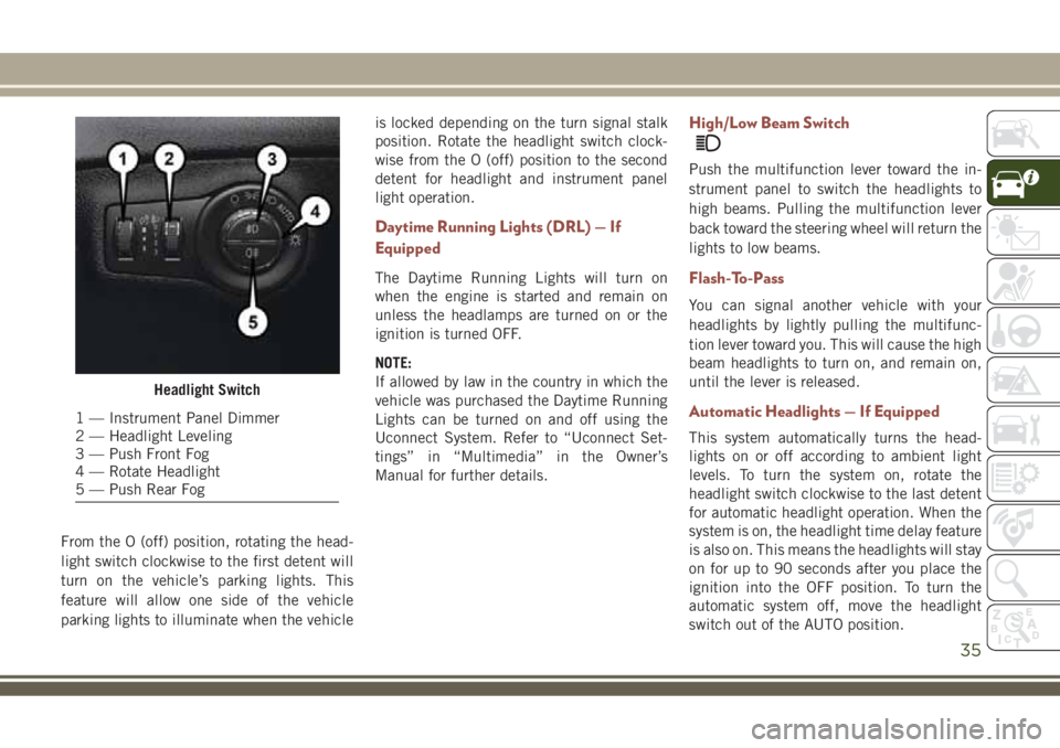
From the O (off) position, rotating the head-
light switch clockwise to the first detent will
turn on the vehicle’s parking lights. This
feature will allow one side of the vehicle
parking lights to illuminate when the vehicleis locked depending on the turn signal stalk
position. Rotate the headlight switch clock-
wise from the O (off) position to the second
detent for headlight and instrument panel
light operation.
Daytime Running Lights (DRL) — If
Equipped
The Daytime Running Lights will turn on
when the engine is started and remain on
unless the headlamps are turned on or the
ignition is turned OFF.
NOTE:
If allowed by law in the country in which the
vehicle was purchased the Daytime Running
Lights can be turned on and off using the
Uconnect System. Refer to “Uconnect Set-
tings” in “Multimedia” in the Owner’s
Manual for further details.
High/Low Beam Switch
Push the multifunction lever toward the in-
strument panel to switch the headlights to
high beams. Pulling the multifunction lever
back toward the steering wheel will return the
lights to low beams.
Flash-To-Pass
You can signal another vehicle with your
headlights by lightly pulling the multifunc-
tion lever toward you. This will cause the high
beam headlights to turn on, and remain on,
until the lever is released.
Automatic Headlights — If Equipped
This system automatically turns the head-
lights on or off according to ambient light
levels. To turn the system on, rotate the
headlight switch clockwise to the last detent
for automatic headlight operation. When the
system is on, the headlight time delay feature
is also on. This means the headlights will stay
on for up to 90 seconds after you place the
ignition into the OFF position. To turn the
automatic system off, move the headlight
switch out of the AUTO position.
Headlight Switch
1 — Instrument Panel Dimmer
2 — Headlight Leveling
3 — Push Front Fog
4 — Rotate Headlight
5 — Push Rear Fog
35
Page 38 of 348
NOTE:
The engine must be running before the head-
lights will come on in the automatic mode.
Headlight Time Delay
This feature provides the safety of headlight
illumination for up to 90 seconds (program-
mable) when leaving your vehicle in an unlit
area.
To activate the delay feature, place the igni-
tion in the OFF position while the headlights
are still on. Then, turn off the headlights
within 45 seconds. The delay interval begins
when the headlight switch is turned off.
If you turn the headlights or parking lights on,
or place the ignition in ACC or RUN, the
system will cancel the delay.
If you turn the headlights off before the
ignition, they will turn off in the normal
manner.NOTE:
• The lights must be turned off within
45 seconds of placing the ignition in the
OFF position to activate this feature. If the
headlight switch is in the AUTO position
prior to turning the ignition OFF, there is no
need to turn the headlight switch to off to
activate Headlight Delay.
• The headlight delay time is programmable
using the Uconnect System. Refer to
“Uconnect Settings” in “Multimedia” in
the Owner’s Manual for further details.
Front And Rear Fog Lights — If Equipped
The fog light switches are built into the head-
light switch.
To activate the front fog lights, push the
upper half of the headlight switch. To turn off
the front fog lights, push the upper half of the
headlight switch a second time.
To activate the rear fog lights, push the
lower half of the headlight switch. To turn off
the rear fog lights, push the lower half of the
headlight switch a second time.NOTE:
To turn on the rear fog lamps, the low beam
lamps or front fog lamps must first be active.
An indicator light in the instrument cluster
illuminates when the fog lights are turned on.
Multifunction Lever
The multifunction lever controls the opera-
tion of the turn signals, headlight beam se-
lection and passing lights. The multifunction
lever is located on the left side of the steering
column.
Turn Signals
Move the multifunction lever up or down and
the arrows on each side of the instrument
cluster display flash to show proper operation
of the front and rear turn signal lights.
NOTE:
• If either light remains on and does not
flash, or there is a very fast flash rate, check
for a defective outside light bulb. If an
indicator fails to light when the lever is
moved, it would suggest that the indicator
bulb is defective.
GETTING TO KNOW YOUR VEHICLE
36
Page 41 of 348
shield washers of the vehicle ahead. Rotate
the end of the multifunction lever to one of
two settings to activate this feature.
Automatic Wiping
The sensitivity of the system can be adjusted
with the multifunction lever. Wiper delay po-
sition one is the least sensitive, and wiper
delay position two is the most sensitive. Place
the wiper switch in the O (off) position when
not using the system.
NOTE:
• The Rain Sensing feature will not operate
when the wiper switch is in the low or
high-speed position.
• The Rain Sensing feature may not function
properly when ice or dried salt water is
present on the windshield.
• Use of Rain-X or products containing wax or
silicone may reduce Rain Sensing perfor-
mance.
• The Rain Sensing feature can be turned on
and off using the Uconnect System, refer to
“Uconnect Settings” in “Multimedia” in
the Owner's Manual for further details.The Rain Sensing system has protection fea-
tures for the wiper blades and arms, and will
not operate under the following conditions:
•Change In Ignition Position— If the vehicle
is in Rain Sensing mode and the ignition is
cycled from OFF to ON, the auto wiper will
be suppressed until vehicle speed is greater
than 3 mph (5 km/h), or the wiper switch is
moved out of and back into the Intermittent
wipe position.
•Transmission In NEUTRAL Position— The
Rain Sensing system will not operate if the
NEUTRAL gear is selected in any speed
unless the wiper switch is moved or the gear
selector is moved out of NEUTRAL.
Remote Start Mode Inhibit— On vehicles
equipped with Remote Starting system, Rain
Sensing wipers are not operational when the
vehicle is in the remote start mode. Once the
operator is in the vehicle and has placed the
ignition switch in the ON/RUN position, Rain
Sensing wiper operation can resume, if it has
been selected, and no other inhibit condi-
tions (mentioned previously) exist.
Rear Wiper
The rear wiper/washer controls are located on
the windshield wiper/washer lever on the
right side of the steering column. The rear
wiper/washer is operated by rotating a switch,
located at the middle of the lever.
Rear Wiper Operation
Rotate the center portion of the lever upward
to the first detent for intermittent operation
and to the second detent for continuous rear
wiper operation.
Rear Washer Operation
Push the lever forward and hold while spray is
desired. Once the switch is released, it will
return to the OFF position and the wipers will
cycle several times before returning to the
parked position.
39
Page 50 of 348
WINDOWS
Power Window Controls
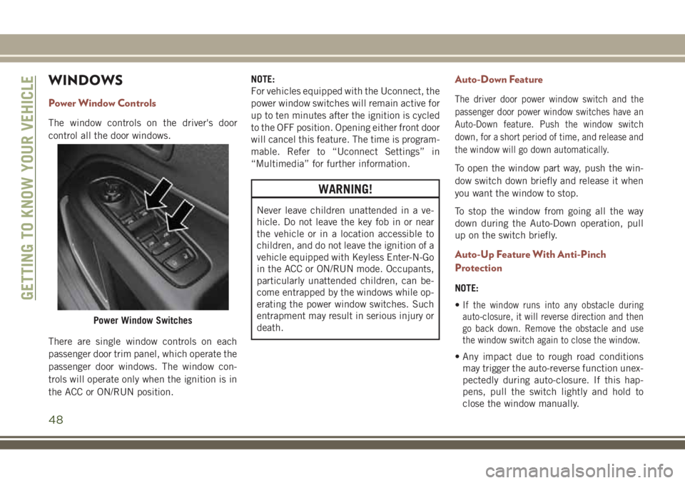
The window controls on the driver's door
control all the door windows.
There are single window controls on each
passenger door trim panel, which operate the
passenger door windows. The window con-
trols will operate only when the ignition is in
the ACC or ON/RUN position.NOTE:
For vehicles equipped with the Uconnect, the
power window switches will remain active for
up to ten minutes after the ignition is cycled
to the OFF position. Opening either front door
will cancel this feature. The time is program-
mable. Refer to “Uconnect Settings” in
“Multimedia” for further information.
WARNING!
Never leave children unattended in a ve-
hicle. Do not leave the key fob in or near
the vehicle or in a location accessible to
children, and do not leave the ignition of a
vehicle equipped with Keyless Enter-N-Go
in the ACC or ON/RUN mode. Occupants,
particularly unattended children, can be-
come entrapped by the windows while op-
erating the power window switches. Such
entrapment may result in serious injury or
death.
Auto-Down Feature
The driver door power window switch and the
passenger door power window switches have an
Auto-Down feature. Push the window switch
down, for a short period of time, and release and
the window will go down automatically.
To open the window part way, push the win-
dow switch down briefly and release it when
you want the window to stop.
To stop the window from going all the way
down during the Auto-Down operation, pull
up on the switch briefly.
Auto-Up Feature With Anti-Pinch
Protection
NOTE:
•
If the window runs into any obstacle during
auto-closure, it will reverse direction and then
go back down. Remove the obstacle and use
the window switch again to close the window.
• Any impact due to rough road conditions
may trigger the auto-reverse function unex-
pectedly during auto-closure. If this hap-
pens, pull the switch lightly and hold to
close the window manually.
Power Window Switches
GETTING TO KNOW YOUR VEHICLE
48
Page 54 of 348
Closing Power Shade — Express
Pull the switch and release it within one-half
second and the shade will close automati-
cally from any position. If the sunroof is
completely closed the shade will close fully
and stop automatically. This is called “Ex-
press Close”. During Express Close opera-
tion, any movement of the switch will stop
the shade.
NOTE:
If the sunroof is open, the shade will close to
the half-open position. Pulling the shade
close button again will automatically close
both the sunroof and shade completely.
Closing Power Shade — Manual Mode
To close the shade, pull and hold the switch
in the close position. Any release of the
switch will stop the movement and the shade
will remain in a partially closed condition
until the switch is pulled again.
Pinch Protection Feature
This feature will detect an obstruction in the
opening of the sunroof during Express Close
operation. If an obstruction in the path of the
sunroof is detected, the sunroof will auto-
matically retract. Remove the obstruction if
this occurs. Next, push the switch forward
and release to Express Close.
NOTE:
If three consecutive sunroof close attempts
result in Pinch Protect reversals, the fourth
close attempt will be a Manual Close move-
ment with Pinch Protect disabled.
WARNING!
• Do not let children play with the sunroof.
Never leave children unattended in a
vehicle, or with access to an unlocked
vehicle. Do not leave the key fob in or
near the vehicle, and do not leave the
ignition of a vehicle equipped with Key-
WARNING!
less Enter-N-Go in the ACC or ON/RUN
mode. Occupants, particularly unat-
tended children, can become entrapped
by the power sunroof while operating the
power sunroof switch. Such entrapment
may result in serious injury or death.
• In a collision, there is a greater risk of
being thrown from a vehicle with an
open sunroof. You could also be severely
injured or killed. Always fasten your seat
belt properly and make sure all passen-
gers are properly secured.
• Do not allow small children to operate
the sunroof. Never allow your fingers,
other body parts, or any object to project
through the sunroof opening. Injury may
result.
Sunroof Maintenance
Use only a non-abrasive cleaner and a soft
cloth to clean the glass panel.
GETTING TO KNOW YOUR VEHICLE
52
Page 58 of 348
WARNING!
• Driving with the liftgate open can allow
poisonous exhaust gases into your ve-
hicle. You and your passengers could be
injured by these fumes. Keep the liftgate
closed when you are operating the ve-
hicle.
• If you are required to drive with the
liftgate open, make sure that all win-
dows are closed, and the climate control
blower switch is set at high speed. Do
not use the recirculation mode.
NOTE:
Allow the power system to open the liftgate.
Manually pushing or pulling the liftgate may
activate the liftgate obstacle detection fea-
ture and stop the power operation or reverse
its direction.
WARNING!
Personal injury or cargo damage may occur
if caught in the path of the liftgate. Make
sure the liftgate path is clear before acti-
vating the liftgate.
INTERNAL EQUIPMENT
Power Outlets
Your vehicle is equipped with 12 Volt
(13 Amp) power outlets that can be used to
power cellular phones, small electronics and
other low powered electrical accessories. The
power outlets are labeled with either a “key”
or a “battery” symbol to indicate how the
outlet is powered. Power outlets labeled with
a “key” are powered when the ignition is in
the ON or ACC position, while the outlets
labeled with a “battery” are connected di-
rectly to the battery and powered at all times.
NOTE:
• All accessories connected to the “battery”
powered outlets should be removed or
turned off when the vehicle is not in use to
protect the battery against discharge.
CAUTION!
Power outlets are designed for accessory
plugs only. Do not insert any other object
in the power outlets as this will damage
the outlet and blow the fuse. Improper use
CAUTION!
of the power outlet can cause damage not
covered by your New Vehicle Limited War-
ranty.
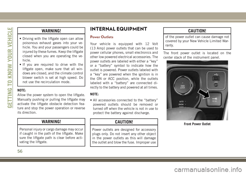
The front power outlet is located on the
center stack of the instrument panel.
Front Power Outlet
GETTING TO KNOW YOUR VEHICLE
56