engine JEEP COMPASS 2018 Owner handbook (in English)
[x] Cancel search | Manufacturer: JEEP, Model Year: 2018, Model line: COMPASS, Model: JEEP COMPASS 2018Pages: 348, PDF Size: 6.03 MB
Page 162 of 348
•SNOW: This mode allows you to have greater
stability under conditions of bad weather.
For use on and off road on surfaces with
poor traction, such as roads covered with
snow. When in SNOW mode (depending on
certain operating conditions), the transmis-
sion may use second gear (rather than first
gear) during launches, to minimize wheel
slippage.
•SAND: For off-road driving or use on sur-
faces with poor traction, such as dry sand.
The transmission is set to provide maxi-
mum traction.
•MUD: For off-road driving or use on surfaces
with poor traction, such as roads covered by
mud or wet grass.
•ROCK(Trailhawk only): This mode is only
available in 4WD LOW range. The device
sets the vehicle to maximize traction and
allow the highest steering capacity for off-
road surfaces. This mode gives you the
maximum performance off-road. Use for
low speed obstacles such as large rocks,
deep ruts, etc.NOTE:
• Rock mode is only available on the vehicles
equipped with the Off-Road package.
• Activate the Hill Descent Control for steep
downhill control. See “Electronic Brake
Control System” in “Safety” for further
information.
STOP/START SYSTEM — IF
EQUIPPED
The Stop/Start function is developed to re-
duce fuel consumption. The system will stop
the engine automatically during a vehicle
stop if the required conditions are met. Re-
leasing the brake pedal, clutch pedal or
pressing the accelerator pedal will automati-
cally re-start the engine.
WARNING!
Before opening the hood, make sure that
the engine is off and that the ignition is in
the OFF mode. Follow the indications on
the plate underneath the hood. We recom-
WARNING!
mend that you remove the key fob if other
people remain in the vehicle. The vehicle
should only be exited after the key fob has
been removed and the ignition is on the
OFF mode. During refueling, make sure
that the engine is off (ignition device in the
OFF mode).
CAUTION!
When replacing the battery, always con-
tact your authorized dealer. Replace the
battery with the same type (HEAVY DUTY)
and with the same specifications.
Operating Modes
Engine stopping mode
Models equipped with a manual transmis-
sion:
With the vehicle stopped, the engine stops
with transmission in neutral and clutch pedal
released.
STARTING AND OPERATING
160
Page 163 of 348
Models equipped with an automatic trans-
mission:
With vehicle at a standstill and brake pedal
pressed, the engine switches off if the gear
selector is in a position other than REVERSE.
In the event of stops uphill, the engine
switching will be disabled to activate the "Hill
Start Assist" function (works only with the
engine running).
The warning light on the instrument panel
switches on to signal that the engine was
stopped.
Engine Restarting Mode
Models equipped with manual transmission:
To restart the engine, press the clutch pedal.
If the vehicle does not start pressing the
clutch, place the gear selector in neutral and
repeat the procedure. If the problem persists,
contact your authorized dealer.
Models equipped with an automatic trans-
mission:
To restart the engine, release the brake pedal.With brake pressed, if the gear selector is in
DRIVE the engine can be restarted moving
the selector to REVERSE or NEUTRAL or
“AutoStick”.
With brake pedal pressed, if the gear selector
is in "AutoStick" mode, the engine can be
restarted moving the selector to "+" or "–", or
REVERSE or NEUTRAL.
When the engine has been stopped automati-
cally, keeping the brake pedal pressed, the
brake can be released keeping the engine off
by quickly shifting the gear selector to PARK.
To restart the engine, just move the selector
out of PARK.
Manual Activation / Deactivation
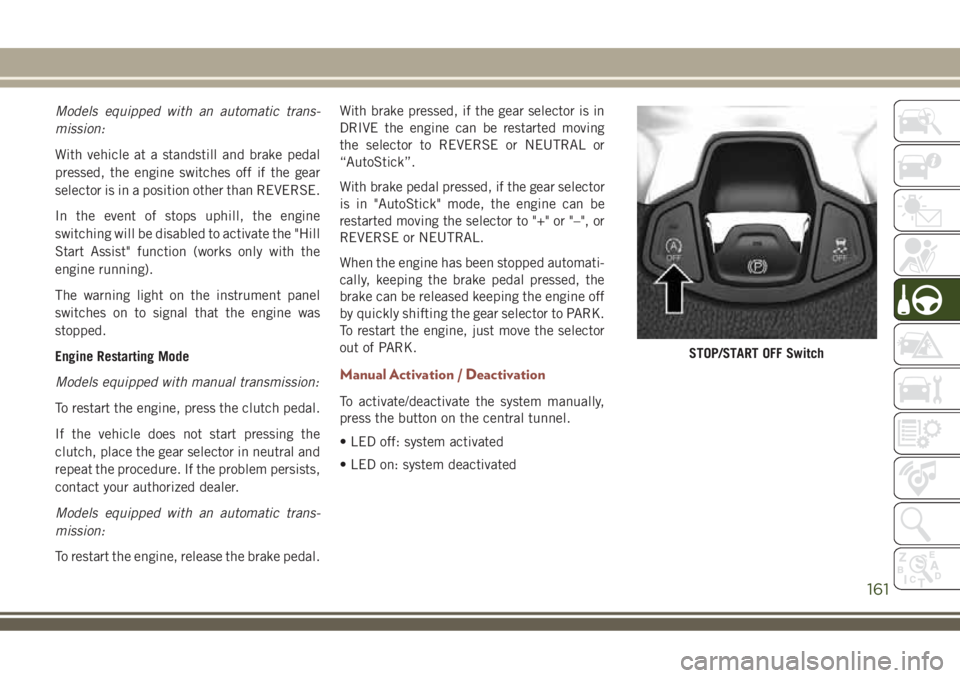
To activate/deactivate the system manually,
press the button on the central tunnel.
• LED off: system activated
• LED on: system deactivated
STOP/START OFF Switch
161
Page 167 of 348
Activation
Push and release the Adaptive Cruise Control
(ACC) on/off button.
“ACC READY” will appear in the instrument
cluster display to indicate the ACC is on.
Setting A Desired Speed
When the vehicle reaches the speed desired,
push the SET(+)button or the SET(-)button
and release. The instrument cluster display
will show the set speed.
If the system is set when the vehicle speed is
below 19 mph (30 km/h), the set speed shall
be defaulted to 19 mph (30 km/h). If the
system is set when the vehicle speed is above
19 mph (30 km/h), the set speed shall be the
current speed of the vehicle.
NOTE:
ACC cannot be set if there is a stationary
vehicle in front of your vehicle in close prox-
imity.Remove your foot from the accelerator pedal.
If you do not, the vehicle may continue to
accelerate beyond the set speed. If this oc-
curs:
• The message “DRIVER OVERRIDE” will
appear in the instrument cluster display.
• The system will not be controlling the dis-
tance between your vehicle and the vehicle
ahead. The vehicle speed will only be de-
termined by the position of the accelerator
pedal.
Varying The Speed
Once the ACC has been activated, the speed
can be increased or decreased.
NOTE:
• When you override and push the SET (+)
button or SET (-) buttons, the new set
speed will be the current speed of the
vehicle.
• When you use the SET (-) button to decel-
erate, if the engine’s braking power does
not slow the vehicle sufficiently to reach
the set speed, the brake system will auto-
matically slow the vehicle.• If equipped with a automatic transmission,
The ACC system decelerates the vehicle to
a full stop when following a target vehicle.
If an ACC host vehicle follows a target
vehicle to a standstill, after two seconds the
driver will either have to push the RES
(resume) button, or apply the accelerator
pedal to reengage the ACC to the existing
set speed.
To Resume
If there is a set speed in the memory, push
the RES button and then remove your foot
from the accelerator pedal. The instrument
cluster display will show the last set speed.
WARNING!
The Resume function should only be used
if traffic and road conditions permit. Re-
suming a set speed that is too high or too
low for prevailing traffic and road condi-
tions could cause the vehicle to accelerate
or decelerate too sharply for safe opera-
tion. Failure to follow these warnings can
result in a collision and death or serious
personal injury.
165
Page 180 of 348
3. Ensure funnel is inserted fully to hold
flapper door open.
4. Pour fuel into funnel opening.
5. Remove funnel from filler pipe, clean off
prior to putting back in the spare tire
storage area.
NOTE:
• In certain cold conditions, ice may prevent
the fuel door from opening. If this occurs,
lightly push on the fuel door to break the ice
buildup and re-release the fuel door using
the inside release button. Do not pry on the
door.
• When the fuel nozzle “clicks” or shuts off,
the fuel tank is full.
WARNING!
• Never have any smoking materials lit in
or near the vehicle when the gas cap is
removed or the tank is being filled.
WARNING!
• Never add fuel when the engine is run-
ning. This is in violation of most state
fire regulations and may cause the MIL
to turn on.
• A fire may result if gasoline is pumped
into a portable container that is inside of
a vehicle. You could be burned. Always
place gas containers on the ground while
filling.
Emergency Fuel Filler Door Release
If you are unable to open the fuel filler door,
use the fuel filler door emergency release.
1. Open the liftgate.
2. Remove package tray if equipped.
3. Remove access door located on right inte-
rior trim panel for release cable with the
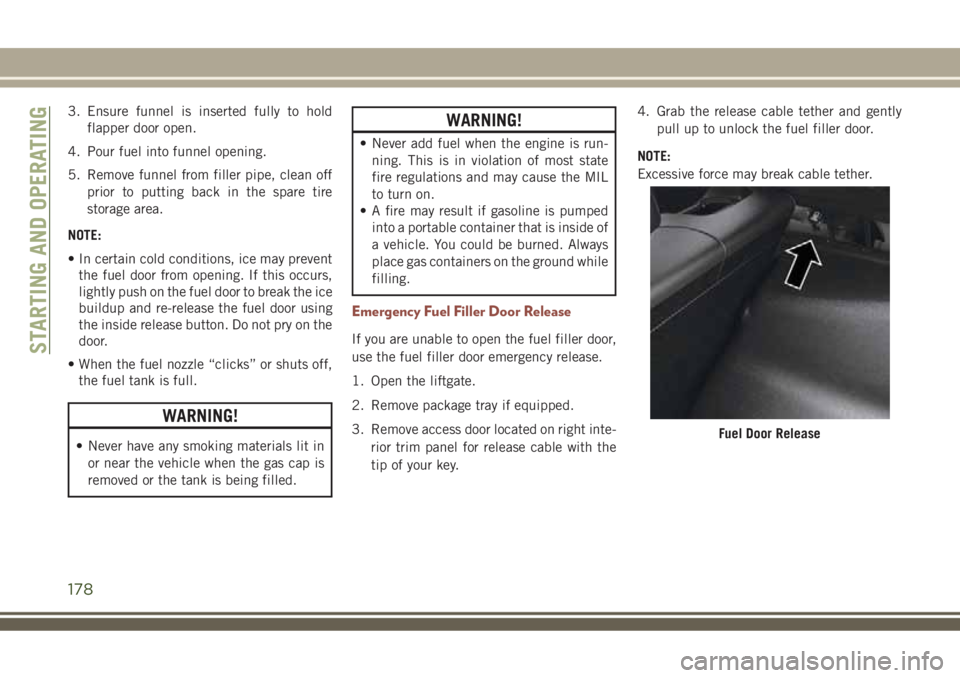
tip of your key.4. Grab the release cable tether and gently
pull up to unlock the fuel filler door.
NOTE:
Excessive force may break cable tether.
Fuel Door Release
STARTING AND OPERATING
178
Page 182 of 348
WARNING!
It is important that you do not exceed the
maximum front or rear GAWR. A danger-
ous driving condition can result if either
rating is exceeded. You could lose control
of the vehicle and have a collision.
Tongue Weight (TW)
The tongue weight is the downward force
exerted on the hitch ball by the trailer. You
must consider this as part of the load on your
vehicle.
Trailer Frontal Area
The frontal area is the maximum height mul-
tiplied by the maximum width of the front of
a trailer.
Trailer Sway Control
The trailer sway control can be a mechanical
telescoping link that can be installed be-
tween the hitch receiver and the trailertongue that typically provides adjustable fric-
tion associated with the telescoping motion
to dampen any unwanted trailer swaying mo-
tions while traveling.
If equipped, the electronic Trailer Sway Con-
trol (TSC) recognizes a swaying trailer and
automatically applies individual wheel
brakes and/or reduces engine power to at-
tempt to eliminate the trailer sway.
Weight-Carrying Hitch
A weight-carrying hitch supports the trailer
tongue weight, just as if it were luggage
located at a hitch ball or some other connect-
ing point of the vehicle. These kinds of
hitches are the most popular on the market
today and they are commonly used to tow
small and medium sized trailers.
Weight-Distributing Hitch
A weight-distributing system works by apply-
ing leverage through spring (load) bars. They
are typically used for heavier loads to distrib-
ute trailer tongue weight to the tow vehicle's
front axle and the trailer axle(s). When used
in accordance with the manufacturer's direc-tions, it provides for a more level ride, offer-
ing more consistent steering and brake con-
trol thereby enhancing towing safety. The
addition of a friction/hydraulic sway control
also dampens sway caused by traffic and
crosswinds and contributes positively to tow
vehicle and trailer stability. Trailer sway con-
trol and a weight distributing (load equaliz-
ing) hitch are recommended for heavier
Tongue Weights (TW) and may be required
depending on vehicle and trailer
configuration/loading to comply with Gross
Axle Weight Rating (GAWR) requirements.
WARNING!
• An improperly adjusted Weight Distrib-
uting Hitch system may reduce han-
dling, stability, braking performance,
and could result in a collision.
• Weight Distributing Systems may not be
compatible with Surge Brake Couplers.
Consult with your hitch and trailer
manufacturer or a reputable Recre-
ational Vehicle dealer for additional in-
formation.
STARTING AND OPERATING
180
Page 183 of 348
Trailer Towing Weights (Maximum Trailer Weight Ratings)
Engine/Transmission Model Maximum GTW (Gross Trailer Wt.) Maximum Tongue Wt. (See Note)
1.4L Gasoline Engine FWD or 4WD 2,205 lbs (1,000 kg) 110 lbs (50 kg)
2.0L Diesel Engine / Automatic 4WD 3,307 lbs (1,500 kg) 165 lbs (75 kg)
2.0L Diesel Engine / Manual 4WD 4,188 lbs (1,900 kg) 209 lbs (95 kg)
1.6L Diesel Engine FWD 2,205 lbs (1,000 kg) 110 lbs (50 kg)
When towing a trailer the technically permissible laden weight may be exceeded by not more than 10% or 220 lbs (100 kg), whichever is lower
provided that the operating speed is restricted to 62 mph (100 km/h) or less.
Refer to local laws for maximum trailer towing speeds and loads.
Towing limits quoted represent the maximum towing ability of the vehicle at its Gross Combined Mass to restart on a 12 percent gradient at sea
level.
The performance and economy of all models will be reduced when used for towing.
Towing Requirements
To promote proper break-in of your new ve-
hicle drivetrain components, the following
guidelines are recommended.
CAUTION!
• Do not tow a trailer at all during the first
500 miles (805 km) the new vehicle is
driven. The engine, axle or other parts
could be damaged.
• Then, during the first 500 miles
(805 km) that a trailer is towed, do not
CAUTION!
drive over 50 mph (80 km/h) and do not
make starts at full throttle. This helps
the engine and other parts of the vehicle
wear in at the heavier loads.
181
Page 184 of 348
Perform the maintenance listed in the
“Scheduled Servicing”. Refer to “Scheduled
Servicing” in “Servicing And Maintenance”
for the proper maintenance intervals. When
towing a trailer, never exceed the GAWR or
GCWR ratings.
WARNING!
Improper towing can lead to a collision.
Follow these guidelines to make your
trailer towing as safe as possible:
• Make certain that the load is secured in
the trailer and will not shift during
travel. When trailering cargo that is not
fully secured, dynamic load shifts can
occur that may be difficult for the driver
to control. You could lose control of your
vehicle and have a collision.
WARNING!
• When hauling cargo or towing a trailer,
do not overload your vehicle or trailer.
Overloading can cause a loss of control,
poor performance or damage to brakes,
axle, engine, transmission, steering,
suspension, chassis structure or tires.
• Safety chains must always be used be-
tween your vehicle and trailer. Always
connect the chains to the hook retainers
of the vehicle hitch. Cross the chains
under the trailer tongue and allow
enough slack for turning corners.
• Vehicles with trailers should not be
parked on a grade. When parking, apply
the parking brake on the tow vehicle. Put
the tow vehicle transmission in PARK.
For four-wheel drive vehicles, make sure
WARNING!
the transfer case is not in NEUTRAL.
Always, block or "chock" the trailer
wheels.
• GCWR must not be exceeded.
•
Total weight must be distributed between
the tow vehicle and the trailer such that
the following four ratings are not ex-
ceeded:
1. GVWR
2. GTW
3. GAWR
4. Tongue weight rating for the trailer
hitch utilized.
STARTING AND OPERATING
182
Page 185 of 348
RECREATIONAL TOWING (BEHIND MOTORHOME, ETC.)
Towing This Vehicle Behind Another Vehicle
TOWING CONDITION WHEELS OFF THE GROUND FRONT WHEEL DRIVE (FWD) FOUR-WHEEL DRIVE (4WD)
Flat Tow NONE NOT ALLOWED NOT ALLOWED
Dolly TowREAR NOT ALLOWED NOT ALLOWED
FRONT OK NOT ALLOWED
On Trailer ALL BEST METHOD OK
NOTE:
• When towing your vehicle, always follow
applicable state and provincial laws. Con-
tact state and provincial Highway Safety
offices for additional details.
• You must ensure that the Auto Park Brake
feature is disabled before towing this ve-
hicle, to avoid inadvertent Electric Park
Brake engagement. The Auto Park Brake
feature is enabled or disabled via the cus-
tomer programmable features in the
Uconnect Settings.Recreational Towing — Front-Wheel Drive
(FWD) Models
Recreational towing is allowed ONLY if the
front wheels areOFFthe ground. This may be
accomplished using a tow dolly (front wheels
off the ground) or vehicle trailer (all four
wheels off the ground). If using a tow dolly,
follow this procedure:
1. Properly secure the dolly to the tow ve-
hicle, following the dolly manufacturer's
instructions.
2. Drive the front wheels onto the tow dolly.3. Apply the Electric Park Brake (EPB).
Place the transmission in PARK. Turn the
engine OFF.
4. Properly secure the front wheels to the
dolly, following the dolly manufacturer's
instructions.
5. Turn the ignition to the ON/RUN position,
but do not start the engine.
6. Press and hold the brake pedal.
7. Release the Electric Park Brake (EPB).
8. Turn the ignition OFF, remove the key fob,
and release the brake pedal.
183
Page 187 of 348
IN CASE OF EMERGENCY
HAZARD WARNING FLASHERS .186
Control....................186
BULB REPLACEMENT........186
Replacement Bulbs.............186
Replacing Exterior Bulbs..........188
FUSES....................192
General Information.............192
Fuse Location................192
Engine Compartment Fuses/Distribution
Unit......................193
Interior Fuses................196
Rear Cargo Fuse/Relay Distribution
Unit......................197
JACKING AND TIRE CHANGING .199
Jack Location/Spare Tire Stowage. . . .199
Road Tire Installation............204
EC Declaration Of Conformance.....204
Jack Usage Precautions..........205
TIRE SERVICE KIT — IF
EQUIPPED................206
JUMP STARTING............211
Preparations For Jump Start........211
Jump Starting Procedure..........212
REFUELING IN EMERGENCY. . . .213
IF YOUR ENGINE OVERHEATS . .214GEAR SELECTOR OVERRIDE . . .214
FREEING A STUCK VEHICLE. . . .215
TOWING A DISABLED VEHICLE .216
Without The Key Fob............217
Front-Wheel Drive (FWD) Models — With
KeyFob....................217
4x4 Models..................218
Emergency Tow Hooks...........218
Tow Eye Usage — If Equipped......218
ENHANCED ACCIDENT RESPONSE
SYSTEM (EARS)............220
EVENT DATA RECORDER (EDR).220
IN CASE OF EMERGENCY
185
Page 191 of 348
NOTE:
We advise referring to an authorized dealer.
WARNING!
Carry out the operation of replacing lamps
only with the engine off. Also make sure
that the engine is cold, to avoid the danger
of burns.
Turn Signal Light/Position Lights/Daytime Run-
ning Lights
To replace the bulbs proceed as follows:
1. Turn the front wheels completely.
2. Remove the wheel liner.
3. Remove the electrical connectors.
4. For the DRL bulb, grip the bulb at the top
and bottom locking tabs and squeeze to
and remove the bulb.
5. To replace the DRL bulb gently push bulb
towards housing. Be sure to hear both the
top and bottom locking tabs “CLICK” to
ensure the bulb is properly seated.6. For the turn signal bulb, rotate in a coun-
terclockwise direction and remove the
bulb and bulb socket. Pull the bulb axially
to remove it from the socket.
7. Install the bulb and sockets and rotate
them clockwise making sure that it is
properly locked.
8. Reconnect the electrical connectors.
9. Reinstall the wheel liner.
NOTE:
We advise referring to an authorized dealer.
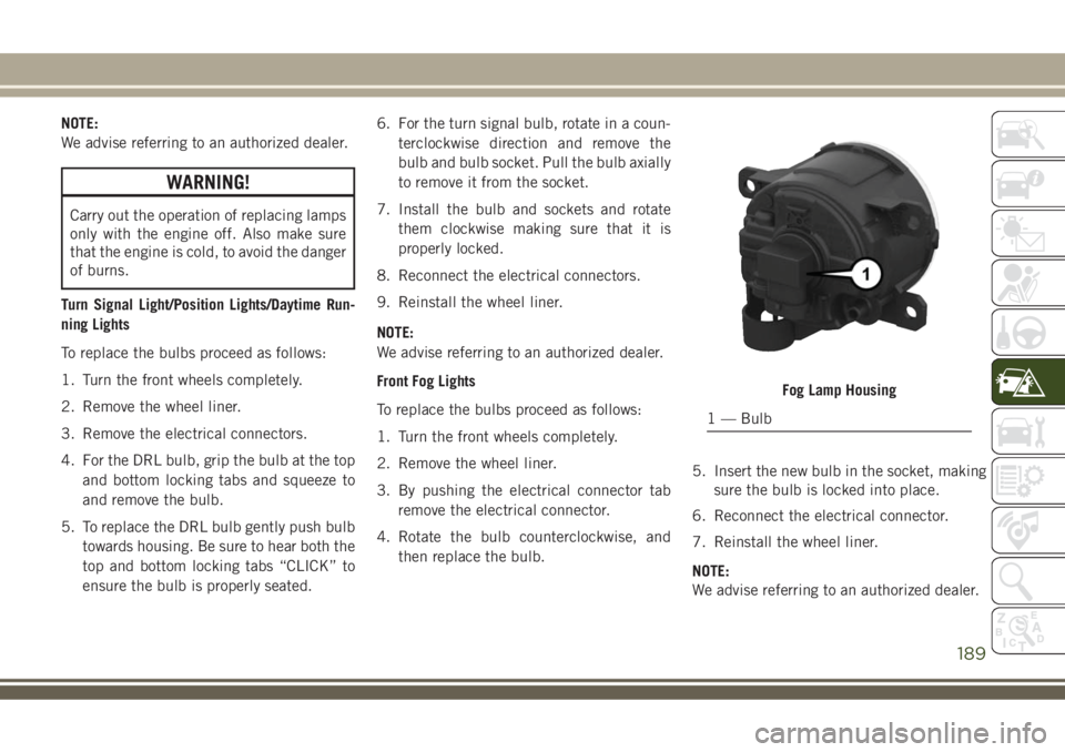
Front Fog Lights
To replace the bulbs proceed as follows:
1. Turn the front wheels completely.
2. Remove the wheel liner.
3. By pushing the electrical connector tab
remove the electrical connector.
4. Rotate the bulb counterclockwise, and
then replace the bulb.5. Insert the new bulb in the socket, making
sure the bulb is locked into place.
6. Reconnect the electrical connector.
7. Reinstall the wheel liner.
NOTE:
We advise referring to an authorized dealer.
Fog Lamp Housing
1 — Bulb
189