engine JEEP COMPASS 2018 Owner handbook (in English)
[x] Cancel search | Manufacturer: JEEP, Model Year: 2018, Model line: COMPASS, Model: JEEP COMPASS 2018Pages: 348, PDF Size: 6.03 MB
Page 194 of 348
Reverse Lamps
1. Open the liftgate.
2. Using a suitable tool remove the access
panel for body side lamps, remove lift gate
access cover for lift gate lamps.
3. Disconnect the electrical connector by
pushing the release.
4. Remove bulb and replace making sure it
is properly locked.
5. Reconnect the electrical connector.
6. Reinstall the access panels making sure
they are locked in correctly.
7. Finally close the tailgate.
3rd Stop Lamp
The CHMSL is LED. For their replacement,
see an authorized dealer.
License Plate Lights
The license plate light is LED. For their
replacement, see an authorized dealer.FUSES
WARNING!
• When replacing a blown fuse, always use
an appropriate replacement fuse with
the same amp rating as the original fuse.
Never replace a fuse with another fuse of
higher amp rating. Never replace a
blown fuse with metal wires or any other
material. Do not place a fuse inside a
circuit breaker cavity or vice versa. Fail-
ure to use proper fuses may result in
serious personal injury, fire and/or prop-
erty damage.
• Before replacing a fuse, make sure that
the ignition is off and that all the other
services are switched off and/or disen-
gaged.
• If the replaced fuse blows again, contact
an authorized dealer.
• If a general protection fuse for safety
systems (air bag system, braking sys-
WARNING!
tem), power unit systems (engine sys-
tem, transmission system) or steering
system blows, contact an authorized
dealer.
General Information
The fuses protect electrical systems against
excessive current.
When a device does not work, you must check
the fuse element inside the blade fuse for a
break/melt.
Also, please be aware that when using power
outlets for extended periods of time with the
engine off may result in vehicle battery dis-
charge.
Fuse Location
The fuses are grouped into controllers lo-
cated in the engine compartment.
IN CASE OF EMERGENCY
192
Page 195 of 348
Engine Compartment Fuses/Distribution
Unit
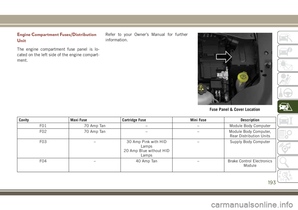
The engine compartment fuse panel is lo-
cated on the left side of the engine compart-
ment.Refer to your Owner’s Manual for further
information.
Cavity Maxi Fuse Cartridge Fuse Mini Fuse Description
F01 70 Amp Tan – – Module Body Computer
F02 70 Amp Tan – – Module Body Computer,
Rear Distribution Units
F03 – 30 Amp Pink with HID
Lamps
20 Amp Blue without HID
Lamps– Supply Body Computer
F04 – 40 Amp Tan – Brake Control Electronics
Module
Fuse Panel & Cover Location
193
Page 196 of 348
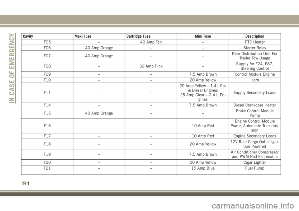
Cavity Maxi Fuse Cartridge Fuse Mini Fuse Description
F05 – 40 Amp Tan – PTC Heater
F06 40 Amp Orange – – Starter Relay
F07 40 Amp Orange – –Rear Distribution Unit For
Trailer Tow Usage
F08 – 30 Amp Pink –Supply for F24, F87,
Steering Control
F09 – – 7.5 Amp Brown Control Module Engine
F10 – – 20 Amp Yellow Horn
F11 – –20 Amp Yellow – 1.4L Gas
& Diesel Engines
25 Amp Clear – 2.4 L En-
ginesSupply Secondary Loads
F14 – – 7.5 Amp Brown Diesel Crankcase Heater
F15 40 Amp Orange – –Brake Control Module
Pump
F16 – – 10 Amp RedEngine Control Module
Power, Automatic Transmis-
sion
F17 – – 10 Amp Red Engine Secondary Loads
F18 – – 20 Amp Yellow12V Rear Cargo Outlet Igni-
tion Powered
F19 – – 7.5 Amp BrownAir Conditioner Compressor
and PWM Rad Fan enable
F20 – – 20 Amp Yellow Cigar Lighter
F21 – – 15 Amp Blue Fuel Pump
IN CASE OF EMERGENCY
194
Page 201 of 348
JACKING AND TIRE
CHANGING
WARNING!
• Do not attempt to change a tire on the
side of the vehicle close to moving traf-
fic. Pull far enough off the road to avoid
the danger of being hit when operating
the jack or changing the wheel.
• Being under a jacked-up vehicle is dan-
gerous. The vehicle could slip off the
jack and fall on you. You could be
crushed. Never put any part of your body
under a vehicle that is on a jack. If you
need to get under a raised vehicle, take
it to a service center where it can be
raised on a lift.
• Never start or run the engine while the
vehicle is on a jack.
• The jack is designed to be used as a tool
for changing tires only. The jack should
not be used to lift the vehicle for service
purposes. The vehicle should be jacked
on a firm level surface only. Avoid ice or
slippery areas.
Jack Location/Spare Tire Stowage
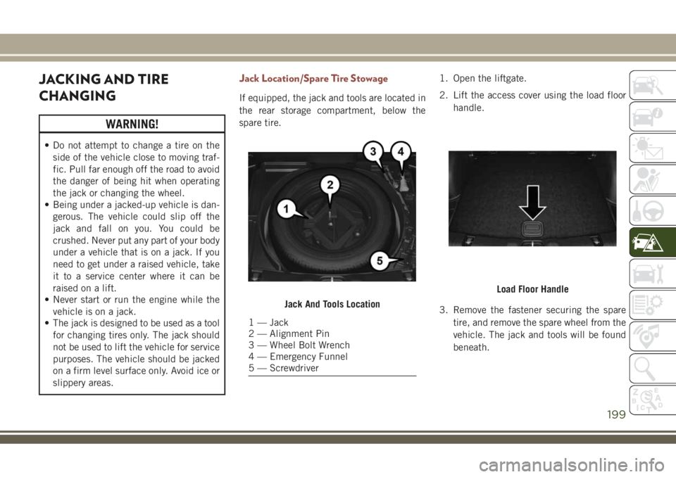
If equipped, the jack and tools are located in
the rear storage compartment, below the
spare tire.1. Open the liftgate.
2. Lift the access cover using the load floor
handle.
3. Remove the fastener securing the spare
tire, and remove the spare wheel from the
vehicle. The jack and tools will be found
beneath.
Jack And Tools Location
1 — Jack
2 — Alignment Pin
3 — Wheel Bolt Wrench
4 — Emergency Funnel
5 — Screwdriver
Load Floor Handle
199
Page 203 of 348
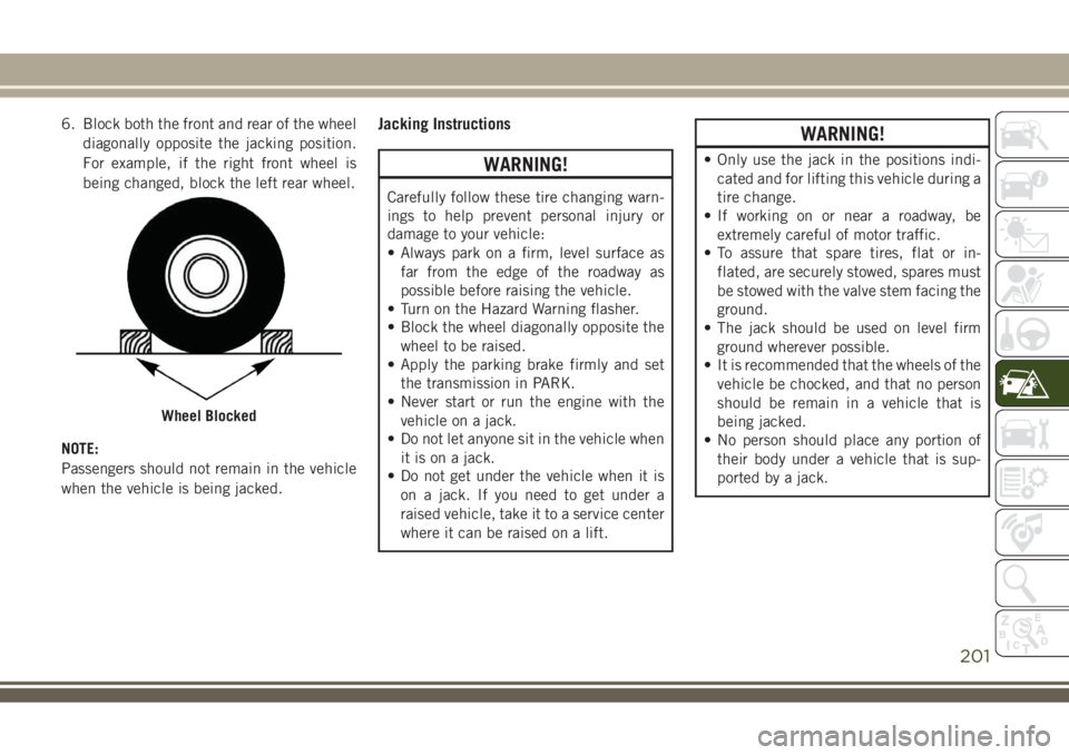
6. Block both the front and rear of the wheel
diagonally opposite the jacking position.
For example, if the right front wheel is
being changed, block the left rear wheel.
NOTE:
Passengers should not remain in the vehicle
when the vehicle is being jacked.Jacking Instructions
WARNING!
Carefully follow these tire changing warn-
ings to help prevent personal injury or
damage to your vehicle:
• Always park on a firm, level surface as
far from the edge of the roadway as
possible before raising the vehicle.
• Turn on the Hazard Warning flasher.
• Block the wheel diagonally opposite the
wheel to be raised.
• Apply the parking brake firmly and set
the transmission in PARK.
• Never start or run the engine with the
vehicle on a jack.
• Do not let anyone sit in the vehicle when
it is on a jack.
• Do not get under the vehicle when it is
on a jack. If you need to get under a
raised vehicle, take it to a service center
where it can be raised on a lift.
WARNING!
• Only use the jack in the positions indi-
cated and for lifting this vehicle during a
tire change.
• If working on or near a roadway, be
extremely careful of motor traffic.
• To assure that spare tires, flat or in-
flated, are securely stowed, spares must
be stowed with the valve stem facing the
ground.
• The jack should be used on level firm
ground wherever possible.
• It is recommended that the wheels of the
vehicle be chocked, and that no person
should be remain in a vehicle that is
being jacked.
• No person should place any portion of
their body under a vehicle that is sup-
ported by a jack.
Wheel Blocked
201
Page 207 of 348
NOTE:
This declaration becomes invalid, if technical
or operational modifications are introduced
without the manufacture’s consent. Follow
operational manual and instructions for use.Jack Usage Precautions
To complete the Use and Maintenance Hand-
book to which this supplement is attached,
given below are some instructions on the
proper use of the jack.
WARNING!
When using the crank, make sure it turns
freely without the risk of scraping hands
against the ground.
Even the moving parts of the jack, the
“worm screw” and joints can cause inju-
ries: avoid contact with them. Clean it
thoroughly if dirtied with grease.
CAUTION!
The jack is a tool designed exclusively for
changing a wheel, in case of a puncture or
damage to a tire of the vehicle on which it
is fitted or on vehicles of the same model.
Any other use, e.g. to jack up other vehicle
models or different things, is strictly pro-
hibited. Never use it to carry out mainte-
nance or repairs under the vehicle or to
CAUTION!
change summer/winter wheels and vice
versa. Never go under the raised vehicle. If
any work under the vehicle is necessary,
contact the Fiat Service Network. Incor-
rect placing of the jack can cause the
vehicle to drop: use it only in the positions
indicated. Do not use the jack for loads
higher than that specified on the label.
Never start the engine with vehicle raised.
If the vehicle is raised more than neces-
sary, everything can become more un-
stable, with the risk of the vehicle drop-
ping violently. Therefore raise the vehicle
only as much as necessary for the wheel/
spare.
Maintenance
• Make sure grime does not build up on the
“worm screw.”
• Keep the “worm screw” lubricated.
• Never modify the jack.
German Translation
205
Page 213 of 348
4. Have the tire inspected and repaired or
replaced at the earliest opportunity at
your authorized dealer or tire service
center.
5. Remove the Speed Limit sticker from the
steering wheel after the tire has been
repaired.
6. Replace the Sealant Bottle at your autho-
rized dealer as soon as possible. Refer to
“Sealant Bottle Replacement”.
NOTE:
When having the tire serviced, advise the
authorized dealer or service center that the
tire has been sealed using the Tire Service
Kit.
Sealant Bottle Replacement:
1. Unwrap the power cord.
2. Unwrap the hose.
3. Remove the bottle cover.
4. Rotate the bottle up beyond vertical to
release.
5. Pull the bottle away from the Compressor.NOTE:
• For sealant bottle installation, follow these
steps reverse order.
• Replacement sealant bottles are available
at authorized service centers.
JUMP STARTING
If your vehicle has a discharged battery, it can
be jump started using a set of jumper cables
and a battery in another vehicle or by using a
portable battery booster pack. Jump starting
can be dangerous if done improperly, so
please follow the procedures in this section
carefully.
NOTE:
When using a portable battery booster pack,
follow the manufacturer’s operating instruc-
tions and precautions.
WARNING!
Do not attempt jump starting if the battery
is frozen. It could rupture or explode and
cause personal injury.
CAUTION!
Do not use a portable battery booster pack
or any other booster source with a system
voltage greater than 12 Volts or damage to
the battery, starter motor, alternator or
electrical system may occur.
Preparations For Jump Start
The battery in your vehicle is located in the
front of the engine compartment, behind the
left headlight assembly.
NOTE:
The positive battery post is covered with a
protective cap. Lift up on the cap to gain
access to the post.
211
Page 215 of 348
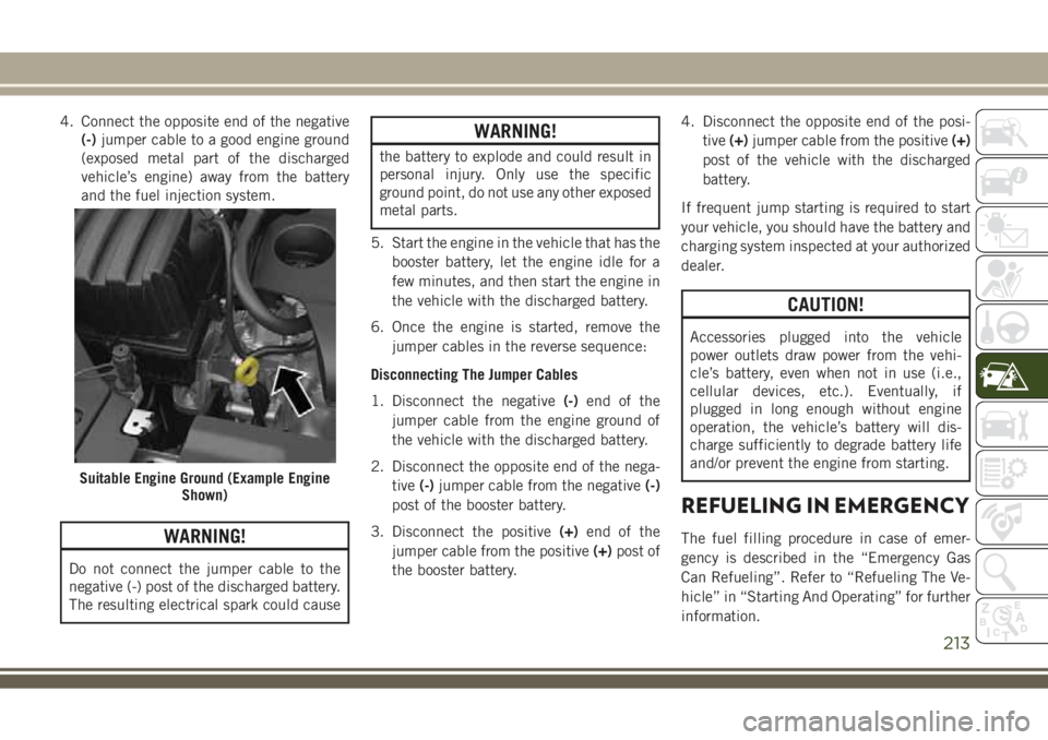
4. Connect the opposite end of the negative
(-)jumper cable to a good engine ground
(exposed metal part of the discharged
vehicle’s engine) away from the battery
and the fuel injection system.
WARNING!
Do not connect the jumper cable to the
negative (-) post of the discharged battery.
The resulting electrical spark could cause
WARNING!
the battery to explode and could result in
personal injury. Only use the specific
ground point, do not use any other exposed
metal parts.
5. Start the engine in the vehicle that has the
booster battery, let the engine idle for a
few minutes, and then start the engine in
the vehicle with the discharged battery.
6. Once the engine is started, remove the
jumper cables in the reverse sequence:
Disconnecting The Jumper Cables
1. Disconnect the negative(-)end of the
jumper cable from the engine ground of
the vehicle with the discharged battery.
2. Disconnect the opposite end of the nega-
tive(-)jumper cable from the negative(-)
post of the booster battery.
3. Disconnect the positive(+)end of the
jumper cable from the positive(+)post of
the booster battery.4. Disconnect the opposite end of the posi-
tive(+)jumper cable from the positive(+)
post of the vehicle with the discharged
battery.
If frequent jump starting is required to start
your vehicle, you should have the battery and
charging system inspected at your authorized
dealer.
CAUTION!
Accessories plugged into the vehicle
power outlets draw power from the vehi-
cle’s battery, even when not in use (i.e.,
cellular devices, etc.). Eventually, if
plugged in long enough without engine
operation, the vehicle’s battery will dis-
charge sufficiently to degrade battery life
and/or prevent the engine from starting.
REFUELING IN EMERGENCY
The fuel filling procedure in case of emer-
gency is described in the “Emergency Gas
Can Refueling”. Refer to “Refueling The Ve-
hicle” in “Starting And Operating” for further
information.
Suitable Engine Ground (Example Engine
Shown)
213
Page 216 of 348
IF YOUR ENGINE
OVERHEATS
In any of the following situations, you can
reduce the potential for overheating your en-
gine by taking the appropriate action.
• On the highways — slow down.
• In city traffic — while stopped, place the
transmission in NEUTRAL, but do not in-
crease engine idle speed.
CAUTION!
Driving with a hot cooling system could
damage your vehicle. If the temperature
gauge reads “H,” pull over and stop the
vehicle. Idle the vehicle with the air con-
ditioner turned off until the pointer drops
back into the normal range. If the pointer
remains on the “H” and you hear continu-
ous chimes, turn the engine off immedi-
ately and call for service.NOTE:
There are steps that you can take to slow
down an impending overheat condition:
• If your air conditioner (A/C) is on, turn it off.
The A/C system adds heat to the engine
cooling system and turning the A/C off can
help remove this heat.
• You can also turn the temperature control
to maximum heat, the mode control to floor
and the blower control to high. This allows
the heater core to act as a supplement to
the radiator and aids in removing heat from
the engine cooling system.WARNING!
You or others can be badly burned by hot
engine coolant (antifreeze) or steam from
your radiator. If you see or hear steam
coming from under the hood, do not open
the hood until the radiator has had time to
cool. Never try to open a cooling system
pressure cap when the radiator or coolant
bottle is hot.
GEAR SELECTOR OVERRIDE
If a malfunction occurs, and the gear selector
cannot be moved out of the PARK position,
you can use the following procedure to tem-
porarily move the gear selector:
1. Turn the engine OFF.
2. Apply the park brake.
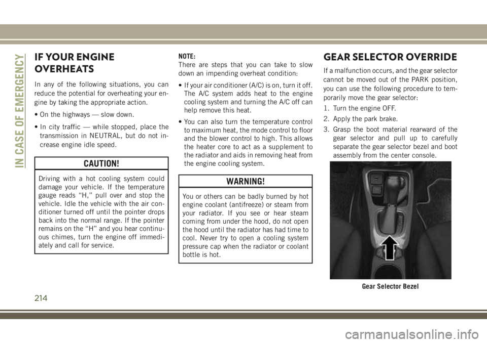
3. Grasp the boot material rearward of the
gear selector and pull up to carefully
separate the gear selector bezel and boot
assembly from the center console.
Gear Selector Bezel
IN CASE OF EMERGENCY
214
Page 217 of 348
4. Press and maintain firm pressure on the
brake pedal.
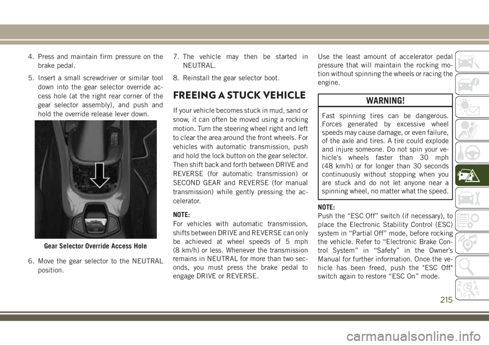
5. Insert a small screwdriver or similar tool
down into the gear selector override ac-
cess hole (at the right rear corner of the
gear selector assembly), and push and
hold the override release lever down.
6. Move the gear selector to the NEUTRAL
position.7. The vehicle may then be started in
NEUTRAL.
8. Reinstall the gear selector boot.
FREEING A STUCK VEHICLE
If your vehicle becomes stuck in mud, sand or
snow, it can often be moved using a rocking
motion. Turn the steering wheel right and left
to clear the area around the front wheels. For
vehicles with automatic transmission, push
and hold the lock button on the gear selector.
Then shift back and forth between DRIVE and
REVERSE (for automatic transmission) or
SECOND GEAR and REVERSE (for manual
transmission) while gently pressing the ac-
celerator.
NOTE:
For vehicles with automatic transmission,
shifts between DRIVE and REVERSE can only
be achieved at wheel speeds of 5 mph
(8 km/h) or less. Whenever the transmission
remains in NEUTRAL for more than two sec-
onds, you must press the brake pedal to
engage DRIVE or REVERSE.Use the least amount of accelerator pedal
pressure that will maintain the rocking mo-
tion without spinning the wheels or racing the
engine.
WARNING!
Fast spinning tires can be dangerous.
Forces generated by excessive wheel
speeds may cause damage, or even failure,
of the axle and tires. A tire could explode
and injure someone. Do not spin your ve-
hicle's wheels faster than 30 mph
(48 km/h) or for longer than 30 seconds
continuously without stopping when you
are stuck and do not let anyone near a
spinning wheel, no matter what the speed.
NOTE:
Push the “ESC Off” switch (if necessary), to
place the Electronic Stability Control (ESC)
system in “Partial Off” mode, before rocking
the vehicle. Refer to “Electronic Brake Con-
trol System” in “Safety” in the Owner’s
Manual for further information. Once the ve-
hicle has been freed, push the "ESC Off"
switch again to restore “ESC On” mode.
Gear Selector Override Access Hole
215