ignition JEEP COMPASS 2018 Owner handbook (in English)
[x] Cancel search | Manufacturer: JEEP, Model Year: 2018, Model line: COMPASS, Model: JEEP COMPASS 2018Pages: 348, PDF Size: 6.03 MB
Page 159 of 348
In the event of a momentary problem, the
transmission can be reset to regain all for-
ward gears by performing the following steps:
1. Stop the vehicle.
2. Shift the transmission into PARK, if pos-
sible. If not, shift the transmission to
NEUTRAL.
3. Turn the ignition to the OFF position. On
vehicles with push button start, push and
hold the ignition until the engine turns
OFF.
4. Wait approximately 30 seconds.
5. Restart the engine.
6. Shift into the desired gear range. If the
problem is no longer detected, the trans-
mission will return to normal operation.
NOTE:
Even if the transmission can be reset, we
recommend that you visit your authorized
dealer at your earliest possible convenience.
Your authorized dealer has diagnostic equip-
ment to assess the condition of your trans-
mission. If the transmission cannot be reset,
authorized dealer service is required.Torque Converter Clutch
A feature designed to improve fuel economy
has been included in the automatic transmis-
sion on your vehicle. A clutch within the
torque converter engages automatically at
calibrated speeds. This may result in a
slightly different feeling or response during
normal operation in the upper gears. When
the vehicle speed drops or during some ac-
celerations, the clutch automatically disen-
gages.
NOTE:
The torque converter clutch will not engage
until the engine and/or transmission is warm
(usually after 1 to 3 miles [2 to 5 km] of
driving). Because the engine speed is higher
when the torque converter clutch is not en-
gaged, it may seem as if the transmission is
not shifting properly when the vehicle is cold.
This is normal. The torque converter clutch
will function normally once the powertrain is
sufficiently warm.FOUR-WHEEL DRIVE
OPERATION — IF EQUIPPED
Jeep Active Drive
Your vehicle may be equipped with a Power
Transfer Unit (PTU). This system is automatic
with no driver inputs or additional driving
skills required. Under normal driving condi-
tions, the front wheels provide most of the
traction. If the front wheels begin to lose
traction, power is shifted automatically to the
rear wheels. The greater the front wheel trac-
tion loss, the greater the power transfer to the
rear wheels.
Additionally, on dry pavement under heavy
throttle input (where one may have no wheel
spin), torque will be sent to the rear in a
preemptive effort to improve vehicle launch
and performance characteristics.
157
Page 161 of 348
The 4WD LOW mode helps to improve the
off-road performance in all modes. To enable
4WD LOW, please follow the steps below:
Enabling 4WD LOW
With the vehicle stationary, the ignition in the
ON/RUN or with the engine running, shift the
transmission into NEUTRAL and push the
button once 4WD LOW. The instrument clus-
ter will display the message "4WD LOW" once
the shift is complete.
NOTE:
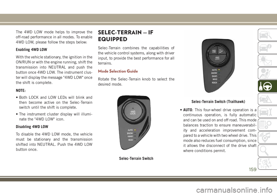
• Both LOCK and LOW LEDs will blink and
then become active on the Selec-Terrain
switch until the shift is complete.
• The instrument cluster display will illumi-
nate the "4WD LOW" icon.
Disabling 4WD LOW
To disable the 4WD LOW mode, the vehicle
must be stationary and the transmission
shifted into NEUTRAL. Push the 4WD LOW
button once.SELEC-TERRAIN — IF
EQUIPPED
Selec-Terrain combines the capabilities of
the vehicle control systems, along with driver
input, to provide the best performance for all
terrains.
Mode Selection Guide
Rotate the Selec-Terrain knob to select the
desired mode.
•AUTO: This four-wheel drive operation is a
continuous operation, is fully automatic
and can be used on and off road. This mode
balances traction to ensure maneuverabil-
ity and acceleration improvement com-
pared to a vehicle with two wheel drive. This
mode also reduces fuel consumption, since
it allows the disconnect of the drive shaft
where conditions permit.
Selec-Terrain Switch
Selec-Terrain Switch (Trailhawk)
159
Page 162 of 348
•SNOW: This mode allows you to have greater
stability under conditions of bad weather.
For use on and off road on surfaces with
poor traction, such as roads covered with
snow. When in SNOW mode (depending on
certain operating conditions), the transmis-
sion may use second gear (rather than first
gear) during launches, to minimize wheel
slippage.
•SAND: For off-road driving or use on sur-
faces with poor traction, such as dry sand.
The transmission is set to provide maxi-
mum traction.
•MUD: For off-road driving or use on surfaces
with poor traction, such as roads covered by
mud or wet grass.
•ROCK(Trailhawk only): This mode is only
available in 4WD LOW range. The device
sets the vehicle to maximize traction and
allow the highest steering capacity for off-
road surfaces. This mode gives you the
maximum performance off-road. Use for
low speed obstacles such as large rocks,
deep ruts, etc.NOTE:
• Rock mode is only available on the vehicles
equipped with the Off-Road package.
• Activate the Hill Descent Control for steep
downhill control. See “Electronic Brake
Control System” in “Safety” for further
information.
STOP/START SYSTEM — IF
EQUIPPED
The Stop/Start function is developed to re-
duce fuel consumption. The system will stop
the engine automatically during a vehicle
stop if the required conditions are met. Re-
leasing the brake pedal, clutch pedal or
pressing the accelerator pedal will automati-
cally re-start the engine.
WARNING!
Before opening the hood, make sure that
the engine is off and that the ignition is in
the OFF mode. Follow the indications on
the plate underneath the hood. We recom-
WARNING!
mend that you remove the key fob if other
people remain in the vehicle. The vehicle
should only be exited after the key fob has
been removed and the ignition is on the
OFF mode. During refueling, make sure
that the engine is off (ignition device in the
OFF mode).
CAUTION!
When replacing the battery, always con-
tact your authorized dealer. Replace the
battery with the same type (HEAVY DUTY)
and with the same specifications.
Operating Modes
Engine stopping mode
Models equipped with a manual transmis-
sion:
With the vehicle stopped, the engine stops
with transmission in neutral and clutch pedal
released.
STARTING AND OPERATING
160
Page 169 of 348
WARNING!
limited upon adverse sight distance con-
ditions.
• Does not always fully recognize complex
driving conditions, which can result in
wrong or missing distance warnings.
• Will bring the vehicle to a complete stop
while following a target vehicle and hold
the vehicle for 2 seconds in the stop
position. If the target vehicle does not
start moving within two seconds the ACC
system will display a message that the
system will release the brakes and that
the brakes must be applied manually. An
audible chime will sound when the
brakes are released.
You should switch off the ACC system:
• When driving in fog, heavy rain, heavy
snow, sleet, heavy traffic, and complex
driving situations (i.e., in highway con-
struction zones).
• When entering a turn lane or highway off
ramp; when driving on roads that are
winding, icy, snow-covered, slippery, or
have steep uphill or downhill slopes.
WARNING!
• When towing a trailer up or down steep
slopes.
• When circumstances do not allow safe
driving at a constant speed.
The Cruise Control system has two control
modes:
• Adaptive Cruise Control mode for main-
taining an appropriate distance between
vehicles.
• Normal (Fixed Speed) Cruise Control
mode for cruising at a constant preset
speed. For additional information, refer
to “Normal (Fixed Speed) Cruise Control
Mode” in your Owner’s Manual for fur-
ther information.
Normal (Fixed Speed) Cruise Control will
not react to preceding vehicles. Always be
aware of the mode selected. You can
change the mode by using the Cruise Con-
trol buttons. The two control modes func-
tion differently. Always confirm which
mode is selected.
PARKSENSE REAR PARK
ASSIST — IF EQUIPPED
The ParkSense Rear Park Assist system pro-
vides visual and audible indications of the
distance between the rear fascia and a de-
tected obstacle when backing up, e.g. during
a parking maneuver. Refer to “ParkSense
System Usage Precautions” for limitations of
this system and recommendations.
ParkSense will retain the last system state
(enabled or disabled) from the last ignition
cycle when the ignition is changed to the
ON/RUN position.
ParkSense can be active only when the gear
selector is in REVERSE. The system will
remain active while in REVERSE until the
vehicle speed is increased to approximately
7 mph (11 km/h) or above. While in RE-
VERSE, and above the system's operating
speed, a warning will appear within the in-
strument cluster display indicating the ve-
hicle speed is too fast. The system will be-
come active again when the vehicle speed is
decreased to speeds less than approximately
6 mph (9 km/h).
167
Page 170 of 348
ParkSense Sensors
The four ParkSense sensors, located in the
rear fascia/bumper, monitor the area behind
the vehicle that is within the sensors’ field of
view. The sensors can detect obstacles from
approximately 12 inches (30 cm) up to
79 inches (200 cm) from the rear fascia/
bumper in the horizontal direction, depend-
ing on the location, type and orientation of
the obstacle.
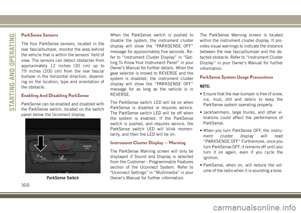
Enabling And Disabling ParkSense
ParkSense can be enabled and disabled with
the ParkSense switch, located on the switch
panel below the Uconnect display.When the ParkSense switch is pushed to
disable the system, the instrument cluster
display will show the “PARKSENSE OFF”
message for approximately five seconds. Re-
fer to “Instrument Cluster Display” in “Get-
ting To Know Your Instrument Panel” in your
Owner’s Manual for further details. When the
gear selector is moved to REVERSE and the
system is disabled, the instrument cluster
display will show the “PARKSENSE OFF”
message for as long as the vehicle is in
REVERSE.
The ParkSense switch LED will be on when
ParkSense is disabled or requires service.
The ParkSense switch LED will be off when
the system is enabled. If the ParkSense
switch is pushed, and requires service, the
ParkSense switch LED will blink momen-
tarily, and then the LED will be on.
Instrument Cluster Display — Warning
The ParkSense Warning screen will only be
displayed if Sound and Display is selected
from the Customer - Programmable Features
section of the Uconnect System. Refer to
"Uconnect Settings” in “Multimedia” in your
Owner's Manual for further information.The ParkSense Warning screen is located
within the instrument cluster display. It pro-
vides visual warnings to indicate the distance
between the rear fascia/bumper and the de-
tected obstacle. Refer to “Instrument Cluster
Display” in your Owner's Manual for further
information.
ParkSense System Usage Precautions
NOTE:
• Ensure that the rear bumper is free of snow,
ice, mud, dirt and debris to keep the
ParkSense system operating properly.
• Jackhammers, large trucks, and other vi-
brations could affect the performance of
ParkSense.
• When you turn ParkSense OFF, the instru-
ment cluster display will read
“PARKSENSE OFF” Furthermore, once you
turn ParkSense OFF, it remains off until you
turn it on again, even if you cycle the
ignition.
• ParkSense, when on, will reduce the vol-
ume of the radio when it is sounding a tone.
ParkSense Switch
STARTING AND OPERATING
168
Page 173 of 348
After the ParkSense has been disengaged, it
will stay in this condition until the following
engagement, even if the ignition device
passes from ON/RUN to OFF and then again
to ON/RUN.
Side Distance Warning System
The Side Distance Warning system has the
function of detecting the presence of side
obstacles near the vehicle using the parking
sensors located in the front and rear bum-
pers.
Side Distance Warning Display
The Side Distance Warning screen will only
be displayed if “Sound and Display” is se-
lected from the Customer - Programmable
Features section of the Uconnect System.
Refer to “Uconnect Settings” in “Multime-
dia” in the Owner’s Manual for further infor-
mation.
The system warns the driver with an acoustic
signal and where provided, with visual indi-
cations on the instrument panel display.NOTE:
Parksense will reduce the volume of the radio
if on when the system is sounding an audible
tone.
Activation — Deactivation
The system can operate only after driving a
short distance and if the vehicle speed is
between 0 and 7 mph (0 and 11 km/h). The
system can be activated/deactivated via the
"Settings" menu of the Uconnect system. If
the ParkSense System is deactivated via the
ParkSense Hard switch then the side dis-
tance warning system will automatically be
deactivated.
Message on the display for Side Distance Warn-
ing feature:
“Wiper Sensors” — This message is dis-
played in the case of a failure of the Side
Distance Warning system sensors. Free the
bumpers of any obstacles, ensure that the
front and rear bumper are free of snow, ice,
mud, dirt and debris to keep the ParkSense
system operating properly.“SDW Not Available” — This message is
displayed if the Side Distance Warning sys-
tem is not available. The failed operation of
the system might be due to the insufficient
voltage from the battery or other failures on
the electrical system. Contact an authorized
dealer as soon as possible to have the elec-
trical system checked.
Operation With A Trailer
The operation of the sensors is automatically
deactivated when the trailer's electric plug is
inserted in the vehicle's tow hook socket. The
sensors are automatically reactivated when
the trailer's cable plug is removed.
General Warnings
If “PARKSENSE UNAVAILABLE WIPE REAR
SENSORS" or "PARKSENSE UNAVAILABLE
WIPE FRONT SENSORS” appears in the in-
strument cluster display, clean the
ParkSense sensors with water, car wash soap
and a soft cloth. Do not use rough or hard
cloths. Do not scratch or poke the sensors.
Otherwise, you could damage the sensors.
171
Page 176 of 348
NOTE:
The LaneSense system will retain the last
system state on or off from the last ignition
cycle when the ignition is changed to the
ON/RUN position.
LaneSense Warning Message
The LaneSense system will indicate the cur-
rent lane drift condition through the instru-
ment cluster display.
Base Instrument Cluster Display — If
Equipped
When the LaneSense system is on; the lane
lines are gray when both of the lane bound-
aries have not been detected and the Lane-
Sense telltale
is solid white.
Left Lane Departure — Only Left Lane Detected
• When the LaneSense system is on, the
LaneSense telltale
is solid white when
only the left lane marking has been de-
tected and the system is ready to provide
visual warnings in the instrument cluster
display if an unintentional lane departure
occurs.• When the LaneSense system senses the
lane has been approached and is in a lane
departure situation, the left thick lane line
flashes from white to gray, the left thin line
remains solid white and the LaneSense
telltale
changes from solid white to
flashing yellow.
NOTE:
The LaneSense system operates with the
similar behavior for a right lane departure
when only the right lane marking has been
detected.
Left Lane Departure — Both Lanes Detected
• When the LaneSense system is on, the lane
lines turn from gray to white to indicate that
both of the lane markings have been de-
tected. The LaneSense telltale
is solid
green when both lane markings have been
detected and the system is “armed” to
provide visual warnings in the instrument
cluster display and a torque warning in the
steering wheel if an unintentional lane de-
parture occurs.• When the LaneSense system senses a lane
drift situation, the left thick lane line and
the left thin line turn solid white. The
LaneSense telltale
changes from solid
green to solid yellow. At this time torque is
applied to the steering wheel in the oppo-
site direction of the lane boundary.
For example: if approaching the left side of
the lane the steering wheel will turn to the
right.
• When the LaneSense system senses the
lane has been approached and is in a lane
departure situation, the left thick lane line
flashes from white to gray, the left thin line
remains solid white and the LaneSense
telltale
changes from solid yellow to
flashing yellow. At this time torque is ap-
plied to the steering wheel in the opposite
direction of the lane boundary.
For example: if approaching the left side of
the lane the steering wheel will turn to the
right.
NOTE:
The LaneSense system operates with the
similar behavior for a right lane departure.
STARTING AND OPERATING
174
Page 185 of 348
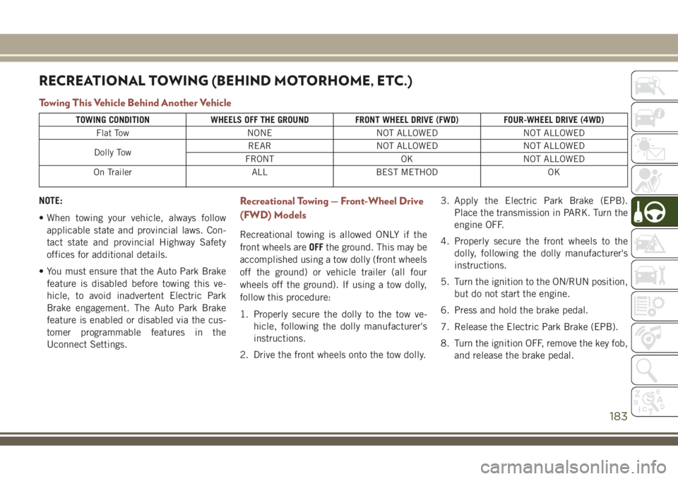
RECREATIONAL TOWING (BEHIND MOTORHOME, ETC.)
Towing This Vehicle Behind Another Vehicle
TOWING CONDITION WHEELS OFF THE GROUND FRONT WHEEL DRIVE (FWD) FOUR-WHEEL DRIVE (4WD)
Flat Tow NONE NOT ALLOWED NOT ALLOWED
Dolly TowREAR NOT ALLOWED NOT ALLOWED
FRONT OK NOT ALLOWED
On Trailer ALL BEST METHOD OK
NOTE:
• When towing your vehicle, always follow
applicable state and provincial laws. Con-
tact state and provincial Highway Safety
offices for additional details.
• You must ensure that the Auto Park Brake
feature is disabled before towing this ve-
hicle, to avoid inadvertent Electric Park
Brake engagement. The Auto Park Brake
feature is enabled or disabled via the cus-
tomer programmable features in the
Uconnect Settings.Recreational Towing — Front-Wheel Drive
(FWD) Models
Recreational towing is allowed ONLY if the
front wheels areOFFthe ground. This may be
accomplished using a tow dolly (front wheels
off the ground) or vehicle trailer (all four
wheels off the ground). If using a tow dolly,
follow this procedure:
1. Properly secure the dolly to the tow ve-
hicle, following the dolly manufacturer's
instructions.
2. Drive the front wheels onto the tow dolly.3. Apply the Electric Park Brake (EPB).
Place the transmission in PARK. Turn the
engine OFF.
4. Properly secure the front wheels to the
dolly, following the dolly manufacturer's
instructions.
5. Turn the ignition to the ON/RUN position,
but do not start the engine.
6. Press and hold the brake pedal.
7. Release the Electric Park Brake (EPB).
8. Turn the ignition OFF, remove the key fob,
and release the brake pedal.
183
Page 188 of 348
HAZARD WARNING
FLASHERS
Control
The Hazard Warning flasher switch is located
on the switch bank just above the climate
controls.
Push the switch to turn on the Hazard Warn-
ing flasher. When the switch is activated, all
directional turn signals will flash on and off towarn oncoming traffic of an emergency. Push
the switch a second time to turn off the
Hazard Warning flashers.
This is an emergency warning system and it
should not be used when the vehicle is in
motion. Use it when your vehicle is disabled
and it is creating a safety hazard for other
motorists.
When you must leave the vehicle to seek
assistance, the Hazard Warning flashers will
continue to operate even though the ignition
is placed in the OFF position.NOTE:
With extended use, the Hazard Warning
flashers may discharge the battery.
BULB REPLACEMENT
Replacement Bulbs
Interior Bulbs
Lamps Bulb Number
Front Courtesy Light C5W
Front Courtesy Lights (Sun Visors) C5W
Rear Dome Light (Models Without Retractable roof) C5W
Rear Interior Lights (Models With Retractable roof) C5W
Interior Lights HT-168
Dome Light (Glove Box) HT-168
IN CASE OF EMERGENCY
186
Page 194 of 348
Reverse Lamps
1. Open the liftgate.
2. Using a suitable tool remove the access
panel for body side lamps, remove lift gate
access cover for lift gate lamps.
3. Disconnect the electrical connector by
pushing the release.
4. Remove bulb and replace making sure it
is properly locked.
5. Reconnect the electrical connector.
6. Reinstall the access panels making sure
they are locked in correctly.
7. Finally close the tailgate.
3rd Stop Lamp
The CHMSL is LED. For their replacement,
see an authorized dealer.
License Plate Lights
The license plate light is LED. For their
replacement, see an authorized dealer.FUSES
WARNING!
• When replacing a blown fuse, always use
an appropriate replacement fuse with
the same amp rating as the original fuse.
Never replace a fuse with another fuse of
higher amp rating. Never replace a
blown fuse with metal wires or any other
material. Do not place a fuse inside a
circuit breaker cavity or vice versa. Fail-
ure to use proper fuses may result in
serious personal injury, fire and/or prop-
erty damage.
• Before replacing a fuse, make sure that
the ignition is off and that all the other
services are switched off and/or disen-
gaged.
• If the replaced fuse blows again, contact
an authorized dealer.
• If a general protection fuse for safety
systems (air bag system, braking sys-
WARNING!
tem), power unit systems (engine sys-
tem, transmission system) or steering
system blows, contact an authorized
dealer.
General Information
The fuses protect electrical systems against
excessive current.
When a device does not work, you must check
the fuse element inside the blade fuse for a
break/melt.
Also, please be aware that when using power
outlets for extended periods of time with the
engine off may result in vehicle battery dis-
charge.
Fuse Location
The fuses are grouped into controllers lo-
cated in the engine compartment.
IN CASE OF EMERGENCY
192