light JEEP COMPASS 2018 Owner handbook (in English)
[x] Cancel search | Manufacturer: JEEP, Model Year: 2018, Model line: COMPASS, Model: JEEP COMPASS 2018Pages: 348, PDF Size: 6.03 MB
Page 157 of 348
WARNING!
Do not coast in NEUTRAL and never turn
off the ignition to coast down a hill. These
are unsafe practices that limit your re-
sponse to changing traffic or road condi-
tions. You might lose control of the vehicle
and have a collision.
CAUTION!
Towing the vehicle, coasting, or driving for
any other reason with the transmission in
NEUTRAL can cause severe transmission
damage.
Refer to “Recreational Towing” in “Start-
ing And Operating” and “Towing A Dis-
abled Vehicle” in “In Case Of Emergency”
for further information.
DRIVE (D)
This range should be used for most city and
highway driving. It provides the smoothest
upshifts and downshifts, and the best fuel
economy. The transmission automatically up-shifts through all forward gears. The DRIVE
position provides optimum driving character-
istics under all normal operating conditions.
When frequent transmission shifting occurs
(such as when operating the vehicle under
heavy loading conditions, in hilly terrain,
traveling into strong head winds, or while
towing a heavy trailer), use the AutoStick
shift control to select a lower gear (refer to
"AutoStick" in this section for further infor-
mation). Under these conditions, using a
lower gear will improve performance and ex-
tend transmission life by reducing excessive
shifting and heat buildup.
If the transmission temperature exceeds nor-
mal operating limits, the transmission con-
troller may modify the transmission shift
schedule, reduce engine torque, and/or ex-
pand the range of torque converter clutch
engagement. This is done to prevent trans-
mission damage due to overheating.
If the transmission becomes extremely hot,
the "Transmission Temperature Warning
Light" may illuminate, and the transmission
may operate differently until the transmis-
sion cools down.During cold temperatures, transmission op-
eration may be modified depending on en-
gine and/or transmission temperature as well
as vehicle speed. This feature improves warm
up time of the engine and transmission to
achieve maximum efficiency. Engagement of
the torque converter clutch (and, for the
nine-speed, shifts into 8th or 9th gear), are
inhibited until the engine and/or transmis-
sion is warm (refer to the “Note” under
“Torque Converter Clutch” in this section).
Normal operation will resume once the tem-
perature(s) have risen to a suitable level.
AUTOSTICK
AutoStick is a driver-interactive transmission
feature providing manual shift control, giving
you more control of the vehicle. AutoStick
allows you to maximize engine braking, elimi-
nate undesirable upshifts and downshifts,
and improve overall vehicle performance.
This system can also provide you with more
control during passing, city driving, cold slip-
pery conditions, mountain driving, trailer
towing, and many other situations.
155
Page 158 of 348
Operation
When the gear selector is in the AutoStick
position (beside the DRIVE position), it can
be moved forward and rearward. This allows
the driver to manually select the transmission
gear being used. Moving the gear selector
forward (-) triggers a downshift and rearward
(+) an upshift. The current gear is displayed
in the instrument cluster.
In AutoStick mode, the transmission will
shift up or down when the driver moves the
gear selector rearward (+) or forward (-), un-
less an engine lugging or overspeed condition
would result. It will remain in the selected
gear until another upshift or downshift is
chosen, except as described below.
• Six-speed transmissions will automatically
upshift when necessary to prevent engine
over-speed.
• The transmission will automatically down-
shift as the vehicle slows (to prevent engine
lugging) and will display the current gear.• The transmission will automatically down-
shift to first gear when coming to a stop.
After a stop, the driver should manually
upshift (+) the transmission as the vehicle
is accelerated.
• You can start out, from a stop, in first or
second gear (or third gear, in six-speed
models, or in 4LO range, Snow mode, or
Sand mode, where available). Tapping (+)
(at a stop) will allow starting in second gear.
Starting out in second gear can be helpful
in snowy or icy conditions.
• If a requested downshift would cause the
engine to over-speed, that shift will not
occur.
• The system will ignore attempts to upshift
at too low of a vehicle speed.
• Transmission shifting will be more notice-
able when AutoStick is enabled.
• The system may revert to automatic shift
mode if a fault or overheat condition is
detected.
NOTE:
When Selec-Speed or Hill Descent Control is
enabled, AutoStick is not active.To disengage AutoStick, return the gear se-
lector to the DRIVE position. You can shift in
or out of the AutoStick position at any time
without taking your foot off the accelerator
pedal.
WARNING!
Do not downshift for additional engine
braking on a slippery surface. The drive
wheels could lose their grip and the ve-
hicle could skid, causing a collision or
personal injury.
Transmission Limp Home Mode
Transmission function is monitored electroni-
cally for abnormal conditions. If a condition
is detected that could result in transmission
damage, Transmission Limp Home Mode is
activated. In this mode, the transmission
may operate only in a fixed gear, or may
remain in NEUTRAL. The Malfunction Indi-
cator Light (MIL) may be illuminated. Limp
Home Mode may allow the vehicle to be
driven to an authorized dealer for service
without damaging the transmission.
STARTING AND OPERATING
156
Page 159 of 348
In the event of a momentary problem, the
transmission can be reset to regain all for-
ward gears by performing the following steps:
1. Stop the vehicle.
2. Shift the transmission into PARK, if pos-
sible. If not, shift the transmission to
NEUTRAL.
3. Turn the ignition to the OFF position. On
vehicles with push button start, push and
hold the ignition until the engine turns
OFF.
4. Wait approximately 30 seconds.
5. Restart the engine.
6. Shift into the desired gear range. If the
problem is no longer detected, the trans-
mission will return to normal operation.
NOTE:
Even if the transmission can be reset, we
recommend that you visit your authorized
dealer at your earliest possible convenience.
Your authorized dealer has diagnostic equip-
ment to assess the condition of your trans-
mission. If the transmission cannot be reset,
authorized dealer service is required.Torque Converter Clutch
A feature designed to improve fuel economy
has been included in the automatic transmis-
sion on your vehicle. A clutch within the
torque converter engages automatically at
calibrated speeds. This may result in a
slightly different feeling or response during
normal operation in the upper gears. When
the vehicle speed drops or during some ac-
celerations, the clutch automatically disen-
gages.
NOTE:
The torque converter clutch will not engage
until the engine and/or transmission is warm
(usually after 1 to 3 miles [2 to 5 km] of
driving). Because the engine speed is higher
when the torque converter clutch is not en-
gaged, it may seem as if the transmission is
not shifting properly when the vehicle is cold.
This is normal. The torque converter clutch
will function normally once the powertrain is
sufficiently warm.FOUR-WHEEL DRIVE
OPERATION — IF EQUIPPED
Jeep Active Drive
Your vehicle may be equipped with a Power
Transfer Unit (PTU). This system is automatic
with no driver inputs or additional driving
skills required. Under normal driving condi-
tions, the front wheels provide most of the
traction. If the front wheels begin to lose
traction, power is shifted automatically to the
rear wheels. The greater the front wheel trac-
tion loss, the greater the power transfer to the
rear wheels.
Additionally, on dry pavement under heavy
throttle input (where one may have no wheel
spin), torque will be sent to the rear in a
preemptive effort to improve vehicle launch
and performance characteristics.
157
Page 163 of 348
Models equipped with an automatic trans-
mission:
With vehicle at a standstill and brake pedal
pressed, the engine switches off if the gear
selector is in a position other than REVERSE.
In the event of stops uphill, the engine
switching will be disabled to activate the "Hill
Start Assist" function (works only with the
engine running).
The warning light on the instrument panel
switches on to signal that the engine was
stopped.
Engine Restarting Mode
Models equipped with manual transmission:
To restart the engine, press the clutch pedal.
If the vehicle does not start pressing the
clutch, place the gear selector in neutral and
repeat the procedure. If the problem persists,
contact your authorized dealer.
Models equipped with an automatic trans-
mission:
To restart the engine, release the brake pedal.With brake pressed, if the gear selector is in
DRIVE the engine can be restarted moving
the selector to REVERSE or NEUTRAL or
“AutoStick”.
With brake pedal pressed, if the gear selector
is in "AutoStick" mode, the engine can be
restarted moving the selector to "+" or "–", or
REVERSE or NEUTRAL.
When the engine has been stopped automati-
cally, keeping the brake pedal pressed, the
brake can be released keeping the engine off
by quickly shifting the gear selector to PARK.
To restart the engine, just move the selector
out of PARK.
Manual Activation / Deactivation
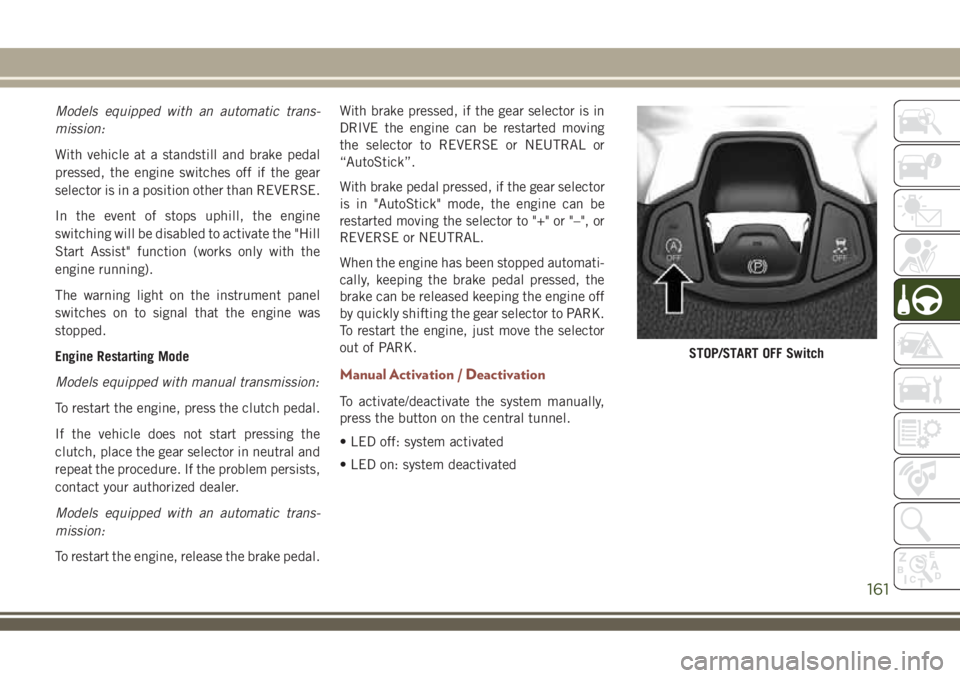
To activate/deactivate the system manually,
press the button on the central tunnel.
• LED off: system activated
• LED on: system deactivated
STOP/START OFF Switch
161
Page 164 of 348
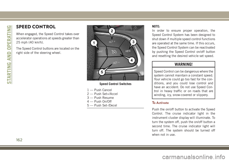
SPEED CONTROL
When engaged, the Speed Control takes over
accelerator operations at speeds greater than
25 mph (40 km/h).
The Speed Control buttons are located on the
right side of the steering wheel.NOTE:
In order to ensure proper operation, the
Speed Control System has been designed to
shut down if multiple speed control functions
are operated at the same time. If this occurs,
the Speed Control System can be reactivated
by pushing the Speed Control on/off button
and resetting the desired vehicle set speed.
WARNING!
Speed Control can be dangerous where the
system cannot maintain a constant speed.
Your vehicle could go too fast for the con-
ditions, and you could lose control and
have an accident. Do not use Speed Con-
trol in heavy traffic or on roads that are
winding, icy, snow-covered or slippery.
To Activate
Push the on/off button to activate the Speed
Control. The cruise indicator light in the
instrument cluster display will illuminate. To
turn the system off, push the on/off button a
second time. The cruise indicator light will
turn off. The system should be turned off
when not in use.
Speed Control Switches
1 — Push Cancel
2 — Push Set+/Accel
3 — Push Resume
4 — Push On/Off
5 — Push Set-/Decel
STARTING AND OPERATING
162
Page 172 of 348
79 inches (200 cm) from the rear fascia/
bumper in the horizontal direction, depend-
ing on the location, type and orientation of
the obstacle.
NOTE:
If your vehicle is equipped with the
ParkSense Active Park Assist system, six sen-
sors will be located in the rear fascia/bumper.
Refer to the "ParkSense Active Park Assist
System" section for further information.
The six ParkSense sensors, located in the
front fascia/bumper, monitor the area in front
of the vehicle that is within the sensors’ field
of view. The sensors can detect obstacles
from approximately 12 inches (30 cm) up to
47 inches (120 cm) from the front fascia/
bumper in the horizontal direction, depend-
ing on the location, type and orientation of
the obstacle.
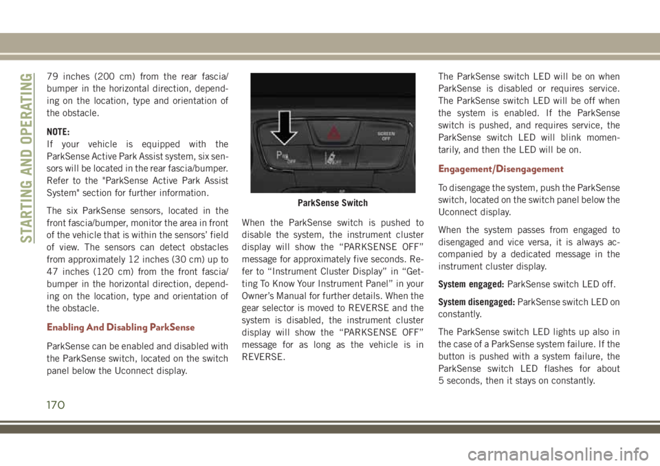
Enabling And Disabling ParkSense
ParkSense can be enabled and disabled with
the ParkSense switch, located on the switch
panel below the Uconnect display.When the ParkSense switch is pushed to
disable the system, the instrument cluster
display will show the “PARKSENSE OFF”
message for approximately five seconds. Re-
fer to “Instrument Cluster Display” in “Get-
ting To Know Your Instrument Panel” in your
Owner’s Manual for further details. When the
gear selector is moved to REVERSE and the
system is disabled, the instrument cluster
display will show the “PARKSENSE OFF”
message for as long as the vehicle is in
REVERSE.The ParkSense switch LED will be on when
ParkSense is disabled or requires service.
The ParkSense switch LED will be off when
the system is enabled. If the ParkSense
switch is pushed, and requires service, the
ParkSense switch LED will blink momen-
tarily, and then the LED will be on.
Engagement/Disengagement
To disengage the system, push the ParkSense
switch, located on the switch panel below the
Uconnect display.
When the system passes from engaged to
disengaged and vice versa, it is always ac-
companied by a dedicated message in the
instrument cluster display.
System engaged:ParkSense switch LED off.
System disengaged:ParkSense switch LED on
constantly.
The ParkSense switch LED lights up also in
the case of a ParkSense system failure. If the
button is pushed with a system failure, the
ParkSense switch LED flashes for about
5 seconds, then it stays on constantly.
ParkSense Switch
STARTING AND OPERATING
170
Page 180 of 348
3. Ensure funnel is inserted fully to hold
flapper door open.
4. Pour fuel into funnel opening.
5. Remove funnel from filler pipe, clean off
prior to putting back in the spare tire
storage area.
NOTE:
• In certain cold conditions, ice may prevent
the fuel door from opening. If this occurs,
lightly push on the fuel door to break the ice
buildup and re-release the fuel door using
the inside release button. Do not pry on the
door.
• When the fuel nozzle “clicks” or shuts off,
the fuel tank is full.
WARNING!
• Never have any smoking materials lit in
or near the vehicle when the gas cap is
removed or the tank is being filled.
WARNING!
• Never add fuel when the engine is run-
ning. This is in violation of most state
fire regulations and may cause the MIL
to turn on.
• A fire may result if gasoline is pumped
into a portable container that is inside of
a vehicle. You could be burned. Always
place gas containers on the ground while
filling.
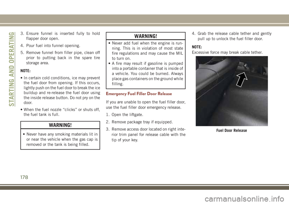
Emergency Fuel Filler Door Release
If you are unable to open the fuel filler door,
use the fuel filler door emergency release.
1. Open the liftgate.
2. Remove package tray if equipped.
3. Remove access door located on right inte-
rior trim panel for release cable with the
tip of your key.4. Grab the release cable tether and gently
pull up to unlock the fuel filler door.
NOTE:
Excessive force may break cable tether.
Fuel Door Release
STARTING AND OPERATING
178
Page 188 of 348
HAZARD WARNING
FLASHERS
Control
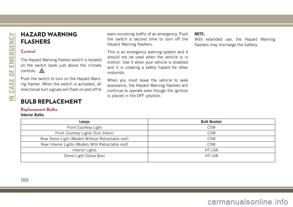
The Hazard Warning flasher switch is located
on the switch bank just above the climate
controls.
Push the switch to turn on the Hazard Warn-
ing flasher. When the switch is activated, all
directional turn signals will flash on and off towarn oncoming traffic of an emergency. Push
the switch a second time to turn off the
Hazard Warning flashers.
This is an emergency warning system and it
should not be used when the vehicle is in
motion. Use it when your vehicle is disabled
and it is creating a safety hazard for other
motorists.
When you must leave the vehicle to seek
assistance, the Hazard Warning flashers will
continue to operate even though the ignition
is placed in the OFF position.NOTE:
With extended use, the Hazard Warning
flashers may discharge the battery.
BULB REPLACEMENT
Replacement Bulbs
Interior Bulbs
Lamps Bulb Number
Front Courtesy Light C5W
Front Courtesy Lights (Sun Visors) C5W
Rear Dome Light (Models Without Retractable roof) C5W
Rear Interior Lights (Models With Retractable roof) C5W
Interior Lights HT-168
Dome Light (Glove Box) HT-168
IN CASE OF EMERGENCY
186
Page 189 of 348
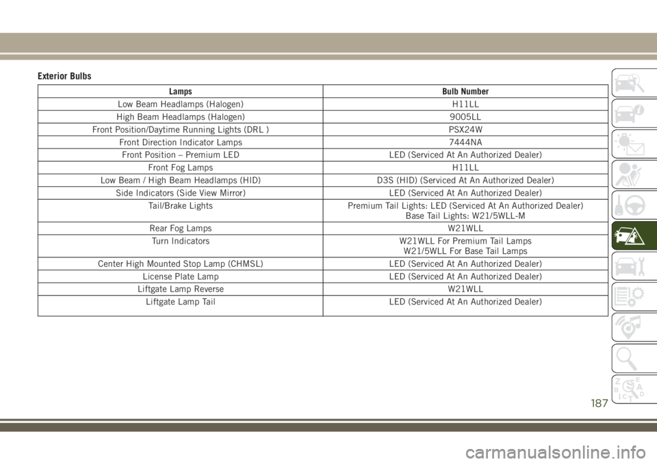
Exterior Bulbs
Lamps Bulb Number
Low Beam Headlamps (Halogen) H11LL
High Beam Headlamps (Halogen) 9005LL
Front Position/Daytime Running Lights (DRL ) PSX24W
Front Direction Indicator Lamps 7444NA
Front Position – Premium LED LED (Serviced At An Authorized Dealer)
Front Fog Lamps H11LL
Low Beam / High Beam Headlamps (HID) D3S (HID) (Serviced At An Authorized Dealer)
Side Indicators (Side View Mirror) LED (Serviced At An Authorized Dealer)
Tail/Brake Lights Premium Tail Lights: LED (Serviced At An Authorized Dealer)
Base Tail Lights: W21/5WLL-M
Rear Fog Lamps W21WLL
Turn Indicators W21WLL For Premium Tail Lamps
W21/5WLL For Base Tail Lamps
Center High Mounted Stop Lamp (CHMSL) LED (Serviced At An Authorized Dealer)
License Plate Lamp LED (Serviced At An Authorized Dealer)
Liftgate Lamp Reverse W21WLL
Liftgate Lamp Tail LED (Serviced At An Authorized Dealer)
187
Page 190 of 348
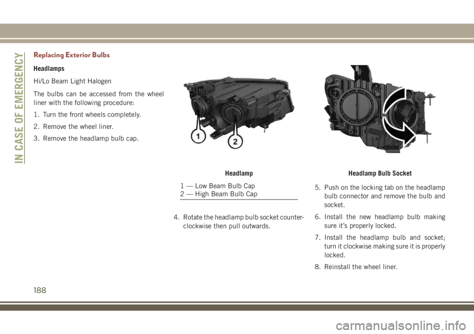
Replacing Exterior Bulbs
Headlamps
Hi/Lo Beam Light Halogen
The bulbs can be accessed from the wheel
liner with the following procedure:
1. Turn the front wheels completely.
2. Remove the wheel liner.
3. Remove the headlamp bulb cap.
4. Rotate the headlamp bulb socket counter-
clockwise then pull outwards.5. Push on the locking tab on the headlamp
bulb connector and remove the bulb and
socket.
6. Install the new headlamp bulb making
sure it’s properly locked.
7. Install the headlamp bulb and socket;
turn it clockwise making sure it is properly
locked.
8. Reinstall the wheel liner.
Headlamp
1 — Low Beam Bulb Cap
2 — High Beam Bulb Cap
Headlamp Bulb Socket
IN CASE OF EMERGENCY
188