charging JEEP COMPASS 2018 Owner handbook (in English)
[x] Cancel search | Manufacturer: JEEP, Model Year: 2018, Model line: COMPASS, Model: JEEP COMPASS 2018Pages: 348, PDF Size: 6.03 MB
Page 64 of 348

The dual brake system provides a reserve brak-
ing capacity in the event of a failure to a portion
of the hydraulic system. A leak in either half of
the dual brake system is indicated by the Brake
Warning Light, which will turn on when the
brake fluid level in the master cylinder has
dropped below a specified level.
The light will remain on until the cause is
corrected.
NOTE:
The light may flash momentarily during sharp
cornering maneuvers, which change fluid
level conditions. The vehicle should have
service performed, and the brake fluid level
checked.
If brake failure is indicated, immediate repair
is necessary.
WARNING!
Driving a vehicle with the red brake light
on is dangerous. Part of the brake system
may have failed. It will take longer to stop
the vehicle. You could have a collision.
Have the vehicle checked immediately.Vehicles equipped with the Anti-Lock Brake
System (ABS) are also equipped with Elec-
tronic Brake Force Distribution (EBD). In the
event of an EBD failure, the Brake Warning
Light will turn on along with the ABS Light.
Immediate repair to the ABS system is re-
quired.
Operation of the Brake Warning Light can be
checked by turning the ignition switch from
the OFF position to the ON/RUN position.
The light should illuminate for approximately
four seconds. The light should then turn off
unless the parking brake is applied or a brake
fault is detected. If the light does not illumi-
nate, have the light inspected by an autho-
rized dealer.
The light also will turn on when the parking
brake is applied with the ignition switch in
the ON/RUN position.
NOTE:
This light shows only that the parking brake is
applied. It does not show the degree of brake
application.
— Battery Charge Warning Light
This light illuminates when the battery is not
charging properly. If it stays on while the
engine is running, there may be a malfunc-
tion with the charging system. Contact your
authorized dealer as soon as possible.
This indicates a possible problem with the
electrical system or a related component.
— Door Open Warning Light
This indicator will illuminate when a door is
ajar/open and not fully closed.
NOTE:
If the vehicle is moving, there will also be a
single chime.
— Electric Power Steering Fault
Warning Light
This light will turn on when there's a fault
with the EPS (Electric Power Steering) sys-
tem. Refer to “Power Steering” in “Starting
And Operating” in the Owner’s Manual for
further information.
GETTING TO KNOW YOUR INSTRUMENT PANEL
62
Page 214 of 348

WARNING!
• Take care to avoid the radiator cooling
fan whenever the hood is raised. It can
start anytime the ignition switch is ON.
You can be injured by moving fan
blades.
• Remove any metal jewelry such as rings,
watch bands and bracelets that could
WARNING!
make an inadvertent electrical contact.
You could be seriously injured.
• Batteries contain sulfuric acid that can
burn your skin or eyes and generate
hydrogen gas which is flammable and
explosive. Keep open flames or sparks
away from the battery.
1. Apply the parking brake, shift the auto-
matic transmission into PARK (manual
transmission in NEUTRAL) and turn the
ignition to OFF/LOCK.
2. Turn off the heater, radio, and all unnec-
essary electrical accessories.
3. If using another vehicle to jump start the
battery, park the vehicle within the
jumper cables reach, set the parking
brake and make sure the ignition is
OFF/LOCK.
WARNING!
Do not allow vehicles to touch each other
as this could establish a ground connec-
tion and personal injury could result.
Jump Starting Procedure
WARNING!
Failure to follow this jump starting proce-
dure could result in personal injury or
property damage due to battery explosion.
CAUTION!
Failure to follow these procedures could
result in damage to the charging system of
the booster vehicle or the discharged ve-
hicle.
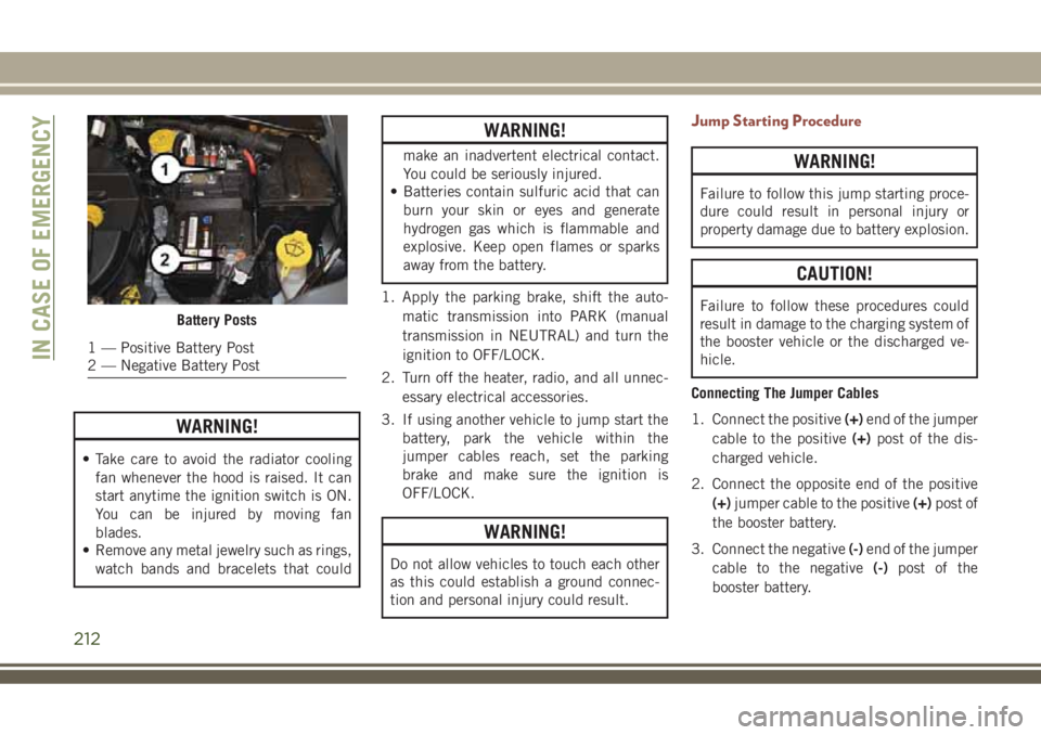
Connecting The Jumper Cables
1. Connect the positive(+)end of the jumper
cable to the positive(+)post of the dis-
charged vehicle.
2. Connect the opposite end of the positive
(+)jumper cable to the positive(+)post of
the booster battery.
3. Connect the negative(-)end of the jumper
cable to the negative(-)post of the
booster battery.Battery Posts
1 — Positive Battery Post
2 — Negative Battery PostIN CASE OF EMERGENCY
212
Page 215 of 348

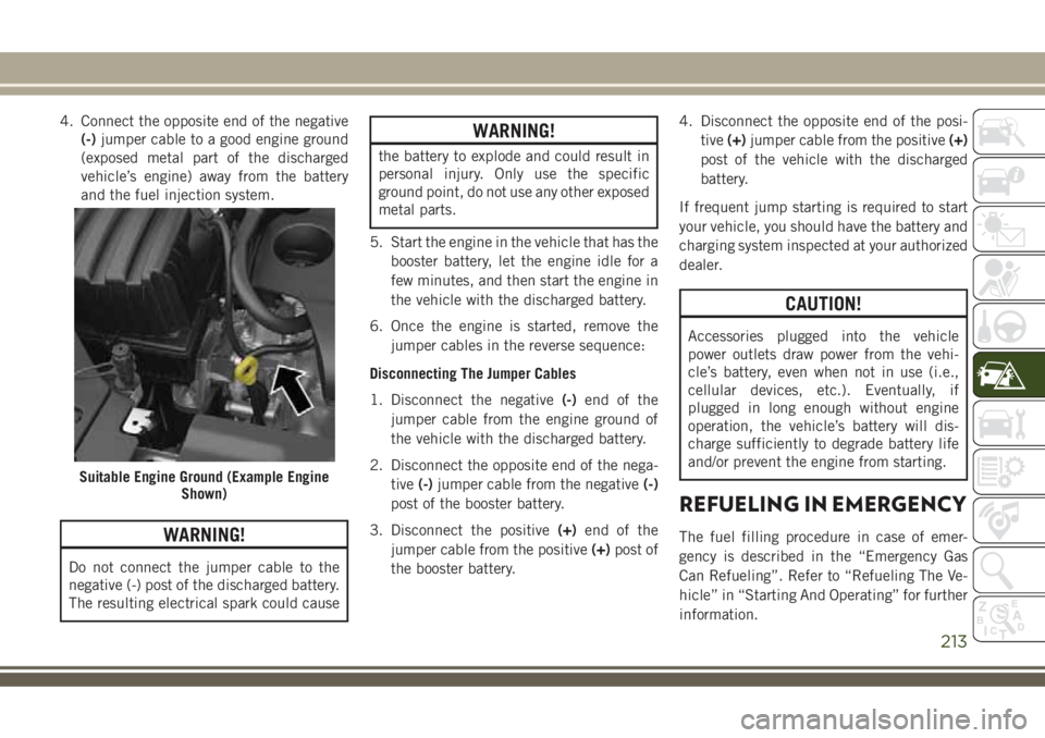
4. Connect the opposite end of the negative
(-)jumper cable to a good engine ground
(exposed metal part of the discharged
vehicle’s engine) away from the battery
and the fuel injection system.
WARNING!
Do not connect the jumper cable to the
negative (-) post of the discharged battery.
The resulting electrical spark could cause
WARNING!
the battery to explode and could result in
personal injury. Only use the specific
ground point, do not use any other exposed
metal parts.
5. Start the engine in the vehicle that has the
booster battery, let the engine idle for a
few minutes, and then start the engine in
the vehicle with the discharged battery.
6. Once the engine is started, remove the
jumper cables in the reverse sequence:
Disconnecting The Jumper Cables
1. Disconnect the negative(-)end of the
jumper cable from the engine ground of
the vehicle with the discharged battery.
2. Disconnect the opposite end of the nega-
tive(-)jumper cable from the negative(-)
post of the booster battery.
3. Disconnect the positive(+)end of the
jumper cable from the positive(+)post of
the booster battery.4. Disconnect the opposite end of the posi-
tive(+)jumper cable from the positive(+)
post of the vehicle with the discharged
battery.
If frequent jump starting is required to start
your vehicle, you should have the battery and
charging system inspected at your authorized
dealer.
CAUTION!
Accessories plugged into the vehicle
power outlets draw power from the vehi-
cle’s battery, even when not in use (i.e.,
cellular devices, etc.). Eventually, if
plugged in long enough without engine
operation, the vehicle’s battery will dis-
charge sufficiently to degrade battery life
and/or prevent the engine from starting.
REFUELING IN EMERGENCY
The fuel filling procedure in case of emer-
gency is described in the “Emergency Gas
Can Refueling”. Refer to “Refueling The Ve-
hicle” in “Starting And Operating” for further
information.
Suitable Engine Ground (Example Engine
Shown)
213
Page 335 of 348

Adaptive Cruise Control (ACC)
Off ..............164, 165, 166
On ..............164, 165, 166
Adaptive Cruise Control (ACC) (Cruise
Control)..................164
Additives, Fuel................256
AirBag ....................107
Air Bag Operation............108
Air Bag Warning Light.........106
Enhanced Accident Response. . . .220
Event Data Recorder (EDR)......220
If A Deployment Occurs........117
Knee Impact Bolsters.........113
Maintaining Your Air Bag System . .119
Redundant Air Bag Warning Light . .106
Side Air Bags..............113
Transporting Pets............135
Air Bag Light...........61, 106, 137
Air Bag Maintenance............119
Air Conditioner Maintenance.......234
Air Conditioning Filter.........47, 235
Air Conditioning, Operating Tips......47
Air Conditioning Refrigerant........234
Air Conditioning System.......46, 234
Air Pressure, Tires..............238Alarm
Arm The System.............20
Disarm The System............20
Alarm (Security Alarm).........19, 64
Alarm System (Security Alarm). . . .19, 21
Antifreeze (Engine Coolant)........258
Anti-Lock Brake System (ABS).......76
Anti-Lock Warning Light...........65
Arming System (Security Alarm)......19
Assist, Hill Start................83
Audio Jack...............274, 282
Audio Systems (Radio)...........267
Auto Down Power Windows.........48
Automatic Dimming Mirror.........34
Automatic Headlights............35
Automatic Temperature Control (ATC) . . .46
Automatic Transaxle............150
Automatic Transmission..........152
Adding Fluid.............
.259
Fluid
Level Check...........237
Fluid Type................259
Auto Up Power Windows...........48
Auxiliary Electrical Outlet (Power Outlet) .56
Auxiliary Power Outlet............56
Axle Fluid...................259Axle Lubrication...............259
Back-Up...................176
Back-Up Camera..............176
Battery..................62, 233
Charging System Light.........62
Belts, Seat..................137
Blind Spot Monitoring............85
Brake Assist System.............77
Brake Control System, Electronic.....77
Brake Fluid..................259
Brake System................236
Fluid Check...........236, 259
Master Cylinder.............236
Parking..................145
Brake/Transmission Interlock.......151
Bulb Replacement.............186
Bulbs, Light.................138
Camera....................176
Capacities, Fluid..............258
Caps, Filler
Fuel....................176
Oil (Engine)...............230
Carbon Monoxide Warning.....136, 257
INDEX
333