steering JEEP COMPASS 2019 Owner handbook (in English)
[x] Cancel search | Manufacturer: JEEP, Model Year: 2019, Model line: COMPASS, Model: JEEP COMPASS 2019Pages: 362, PDF Size: 6.23 MB
Page 203 of 362
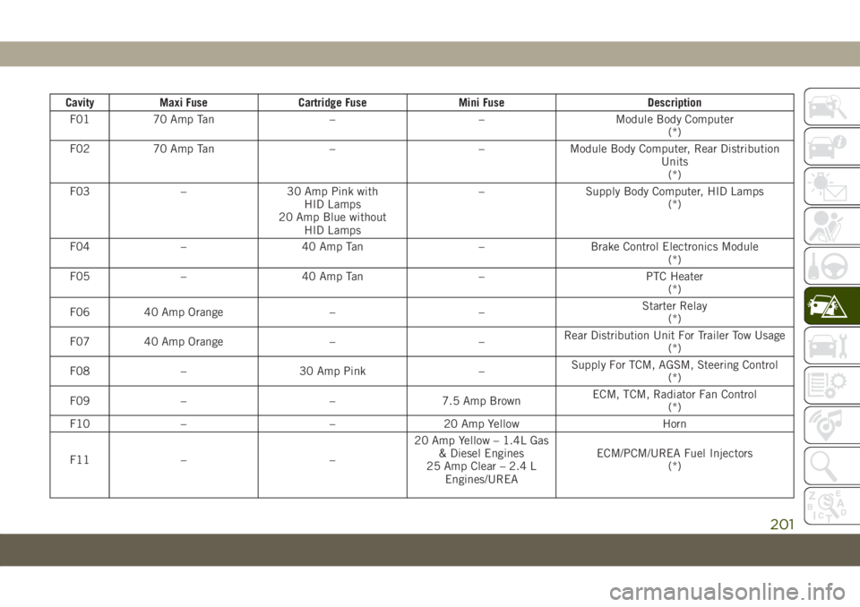
Cavity Maxi Fuse Cartridge Fuse Mini Fuse Description
F01 70 Amp Tan – – Module Body Computer
(*)
F02 70 Amp Tan – – Module Body Computer, Rear Distribution
Units
(*)
F03 – 30 Amp Pink with
HID Lamps
20 Amp Blue without
HID Lamps– Supply Body Computer, HID Lamps
(*)
F04 – 40 Amp Tan – Brake Control Electronics Module
(*)
F05 – 40 Amp Tan – PTC Heater
(*)
F06 40 Amp Orange – –Starter Relay
(*)
F07 40 Amp Orange – –Rear Distribution Unit For Trailer Tow Usage
(*)
F08 – 30 Amp Pink –Supply For TCM, AGSM, Steering Control
(*)
F09 – – 7.5 Amp BrownECM, TCM, Radiator Fan Control
(*)
F10 – – 20 Amp Yellow Horn
F11 – –20 Amp Yellow – 1.4L Gas
& Diesel Engines
25 Amp Clear – 2.4 L
Engines/UREAECM/PCM/UREA Fuel Injectors
(*)
201
Page 206 of 362
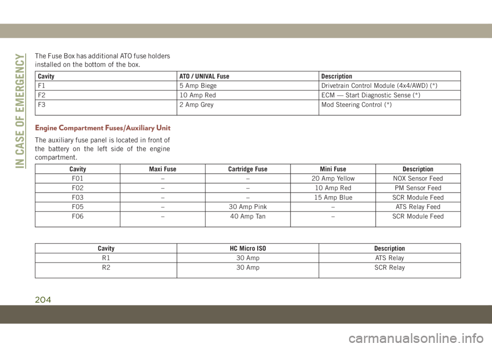
The Fuse Box has additional ATO fuse holders
installed on the bottom of the box.
Cavity ATO / UNIVAL Fuse Description
F1 5 Amp Biege Drivetrain Control Module (4x4/AWD) (*)
F2 10 Amp Red ECM — Start Diagnostic Sense (*)
F3 2 Amp Grey Mod Steering Control (*)
Engine Compartment Fuses/Auxiliary Unit
The auxiliary fuse panel is located in front of
the battery on the left side of the engine
compartment.
Cavity Maxi Fuse Cartridge Fuse Mini Fuse Description
F01 – – 20 Amp Yellow NOX Sensor Feed
F02 – – 10 Amp Red PM Sensor Feed
F03 – – 15 Amp Blue SCR Module Feed
F05 – 30 Amp Pink – ATS Relay Feed
F06 – 40 Amp Tan – SCR Module Feed
Cavity HC Micro ISO Description
R1 30 Amp ATS Relay
R2 30 Amp SCR Relay
IN CASE OF EMERGENCY
204
Page 207 of 362
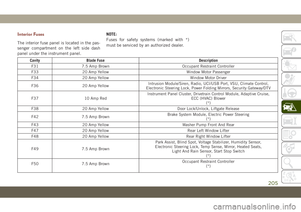
Interior Fuses
The interior fuse panel is located in the pas-
senger compartment on the left side dash
panel under the instrument panel.NOTE:
Fuses for safety systems (marked with *)
must be serviced by an authorized dealer.
Cavity Blade Fuse Description
F31 7.5 Amp Brown Occupant Restraint Controller
F33 20 Amp Yellow Window Motor Passenger
F34 20 Amp Yellow Window Motor Driver
F36 20 Amp YellowIntrusion Module/Siren, Radio, UCI/USB Port, VSU, Climate Control,
Electronic Steering Lock, Power Folding Mirrors, Security Gateway/DTV
F37 10 Amp RedInstrument Panel Cluster, Drivetrain Control Module, Adaptive Cruise,
ECC (HVAC) Blower
(*)
F38 20 Amp Yellow Door Lock/Unlock, Liftgate Release
F42 7.5 Amp BrownBrake System Module, Electric Power Steering
(*)
F43 20 Amp Yellow Washer Pump Front And Rear
F47 20 Amp Yellow Rear Left Window Lifter
F48 20 Amp Yellow Rear Right Window Lifter
F49 7.5 Amp BrownPark Assist, Blind Spot, Voltage Stabilizer, Humidity Sensor,
Electronic Steering Lock, Temp Sense, Mirror, Heated Seats,
Light And Rain Sensor, Start Stop Switch
(*)
F50 7.5 Amp BrownOccupant Restraint Controller
(*)
205
Page 208 of 362
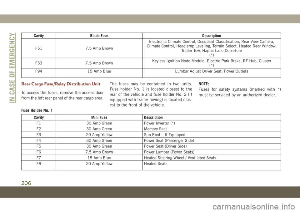
Cavity Blade Fuse Description
F51 7.5 Amp BrownElectronic Climate Control, Occupant Classification, Rear View Camera,
Climate Control, Headlamp Leveling, Terrain Select, Heated Rear Window,
Trailer Tow, Haptic Lane Departure
(*)
F53 7.5 Amp BrownKeyless Ignition Node Module, Electric Park Brake, RF Hub, Cluster
(*)
F94 15 Amp Blue Lumbar Adjust Driver Seat, Power Outlets
Rear Cargo Fuse/Relay Distribution Unit
To access the fuses, remove the access door
from the left rear panel of the rear cargo area.The fuses may be contained in two units.
Fuse holder No. 1 is located closest to the
rear of the vehicle and fuse holder No. 2 (if
equipped with trailer towing) is located clos-
est to the front of the vehicle.NOTE:
Fuses for safety systems (marked with *)
must be serviced by an authorized dealer.
Fuse Holder No. 1
Cavity Mini Fuse Description
F1 30 Amp Green Power Inverter (*)
F2 30 Amp Green Memory Seat
F3 20 Amp Yellow Sun Roof – If Equipped
F4 30 Amp Green Power Seat (Passenger Side)
F5 30 Amp Green Power Seat (Driver Side)
F6 7.5 Amp Brown Power Lumbar (Power Seats)
F7 15 Amp Blue Heated Steering Wheel / Ventilated Seats
F8 20 Amp Yellow Heated Seats
IN CASE OF EMERGENCY
206
Page 222 of 362
4. Have the tire inspected and repaired or
replaced at the earliest opportunity at an
authorized dealer or tire service center.
WARNING!
You must always indicate that the tire was
repaired using the Tire Service Kit. Give
the booklet to the technicians who will be
handling the tire that was treated using
the Tire Service Kit.
5. Remove the Speed Limit sticker from the
steering wheel after the tire has been
repaired.
6. Replace the Sealant Bottle at an autho-
rized dealer as soon as possible. Refer to
“Sealant Bottle Replacement”.
NOTE:
When having the tire serviced, advise the
authorized dealer or service center that the
tire has been sealed using the Tire Service
Kit.
Sealant Bottle Replacement:
1. Unwrap the power cord.
2. Unwrap the hose.3. Remove the bottle cover.
4. Rotate the bottle up beyond vertical to
release.
5. Pull the bottle away from the Compressor.
NOTE:
• For sealant bottle installation, follow these
steps in reverse order.
• Replacement sealant bottles are available
at authorized service centers.
WARNING!
As required by current regulations, the in-
formation on chemical substances for the
protection of human health and the environ-
ment and on the safe use of the sealing fluid
are on the packaging label. Compliance with
the indications on the label is an essential
condition to ensure the safety and effective-
ness of the product. Remember to carefully
read the label before use. The user of the
product is responsible for any damages
caused by improper use. The sealing fluid
has an expiration date. Replace the bottle if
the sealant has expired.
CAUTION!
Dispose of the bottle and the sealant liq-
uid properly. Have them disposed of in
compliance with national and local regu-
lations.
JUMP STARTING
If your vehicle has a discharged battery, it can
be jump started using a set of jumper cables
and a battery in another vehicle or by using a
portable battery booster pack. Jump starting
can be dangerous if done improperly, so
please follow the procedures in this section
carefully.
NOTE:
When using a portable battery booster pack,
follow the manufacturer’s operating instruc-
tions and precautions.
WARNING!
Do not attempt jump starting if the battery
is frozen. It could rupture or explode and
cause personal injury.
IN CASE OF EMERGENCY
220
Page 227 of 362
FREEING A STUCK VEHICLE
If your vehicle becomes stuck in mud, sand or
snow, it can often be moved using a rocking
motion. Turn the steering wheel right and left
to clear the area around the front wheels. For
vehicles with automatic transmission, push
and hold the lock button on the gear selector.
Then shift back and forth between DRIVE and
REVERSE (for automatic transmission) or
SECOND GEAR and REVERSE (for manual
transmission) while gently pressing the ac-
celerator.
NOTE:
For vehicles with automatic transmission,
shifts between DRIVE and REVERSE can only
be achieved at wheel speeds of 5 mph
(8 km/h) or less. Whenever the transmission
remains in NEUTRAL for more than two sec-
onds, you must press the brake pedal to
engage DRIVE or REVERSE.Use the least amount of accelerator pedal
pressure that will maintain the rocking mo-
tion without spinning the wheels or racing the
engine.
WARNING!
Fast spinning tires can be dangerous.
Forces generated by excessive wheel
speeds may cause damage, or even failure,
of the axle and tires. A tire could explode
and injure someone. Do not spin your ve-
hicle's wheels faster than 30 mph
(48 km/h) or for longer than 30 seconds
continuously without stopping when you
are stuck and do not let anyone near a
spinning wheel, no matter what the speed.
NOTE:
Push the “ESC Off” switch (if necessary), to
place the Electronic Stability Control (ESC)
system in “Partial Off” mode, before rocking
the vehicle. Refer to “Electronic Brake Con-
trol System” in “Safety” in the Owner’s
Manual for further information. Once the ve-
hicle has been freed, push the "ESC Off"
switch again to restore “ESC On” mode.
CAUTION!
• Racing the engine or spinning the
wheels may lead to transmission over-
heating and failure. Allow the engine to
idle with the transmission in NEUTRAL
for at least one minute after every five
rocking-motion cycles. This will mini-
mize overheating and reduce the risk of
clutch or transmission failure during
prolonged efforts to free a stuck vehicle.
• When “rocking” a stuck vehicle by shift-
ing between DRIVE/SECOND gear and
REVERSE, do not spin the wheels faster
than 15 mph (24 km/h), or drivetrain
damage may result.
• Revving the engine or spinning the
wheels too fast may lead to transmission
overheating and failure. It can also dam-
age the tires. Do not spin the wheels
above 30 mph (48 km/h) while in gear
(no transmission shifting occurring).
225
Page 230 of 362
CAUTION!
• Towing this vehicle in violation of the
above requirements can cause severe
transmission and/or transfer case dam-
age. Damage from improper towing is
not covered under the New Vehicle Lim-
ited Warranty.
• Proper towing or lifting equipment is
required to prevent damage to your ve-
hicle. Use only tow bars and other equip-
ment designed for this purpose, following
equipment manufacturer's instructions.
• Use of safety chains in mandatory. At-
tach a tow bar or other towing devices to
main structural members of the vehicle,
not to bumpers or associated brackets.
Emergency Tow Hooks
If your vehicle is equipped with tow hooks,
there will be one in the rear and two mounted
on the front of the vehicle. The rear hook will
be located on the driver's side of the vehicle.
NOTE:
For off-road recovery, it is recommended to
use both of the front tow hooks to minimize
the risk of damage to the vehicle.
Vehicles Equipped With Key Fob With
An Integrated Vehicle Key
Turn the ignition key to the ON/RUN and then
the OFF/LOCK position, without removing it.
By extracting the key this will automatically
engage the steering wheel lock. Place the
transmission into NEUTRAL.Vehicles With Keyless Enter-N-Go
Place the ignition in the ON/RUN position,
and subsequently in OFF/LOCK, without
opening the door. During towing, remember
that not having the aid of the power brakes
and the electromechanical power steering
will require greater force when applying the
brakes and steering of the vehicle.
WARNING!
• Do not use a chain for freeing a stuck
vehicle. Chains may break, causing seri-
ous injury or death.
• Stand clear of vehicles when pulling
with tow hooks. Tow straps may become
disengaged, causing serious injury.
CAUTION!
Tow hooks are for emergency use only, to
rescue a vehicle stranded off road. Do not
use tow hooks for tow truck hookup or
highway towing. You could damage your
vehicle.
IN CASE OF EMERGENCY
228
Page 232 of 362
WARNING!
• Failure to follow proper tow eye usage
may cause components to break result-
ing in serious injury or death.
• The brake and steering power assist sys-
tems will not function while the vehicle
is being towed. You will, therefore, need
to apply more force on the brake pedal
and steering wheel. Do not use flexible
ropes when towing, and avoid jerky
movements. Do not start the engine
while towing the car. Before tightening
the ring, clean the threaded housing
thoroughly. Make sure that the ring is
fully screwed into the housing before
towing the car.
Tow Eye Installation
Front Tow Eye
The front tow eye receptacle is located be-
hind a door on the front bumper fascia.To install the tow eye, open the door using the
vehicle key or a small screwdriver, and thread
the tow eye into the receptacle.
Insert the flat end of the jack handle through
the tow eye and tighten, refer to “Jacking And
Tire Changing” in this section for further
information. The tow eye must be fully seated
to the attaching bracket through the lower
front fascia. If the tow eye is not fully seated
to the attaching bracket, the vehicle should
not be moved.
Rear Tow Eye
The rear tow eye receptacle is located behind
a door, located on the right rear bumper
fascia.
To install the tow eye, open the door using the
vehicle key or a small screwdriver, and thread
the tow eye into the receptacle.
Insert the flat end of the jack handle through
the eye and tighten. The tow eye must be fully
seated to the attaching bracket through the
lower rear fascia. If the tow eye is not fully
seated to the attaching bracket, the vehicle
should not be moved.
ENHANCED ACCIDENT
RESPONSE SYSTEM (EARS)
This vehicle is equipped with an Enhanced
Accident Response System.
Please refer to “Occupant Restraint Sys-
tems” in “Safety” for further information on
the Enhanced Accident Response System
(EARS) function.
EVENT DATA RECORDER
(EDR)
This vehicle is equipped with an Event Data
Recorder (EDR). The main purpose of an EDR
is to record data that will assist in under-
standing how a vehicle’s systems performed
under certain crash or near crash-like situa-
tions, such as an air bag deployment or hit-
ting a road obstacle.
Please refer to “Occupant Restraint Sys-
tems” in “Safety” for further information on
the Event Data Recorder (EDR).
IN CASE OF EMERGENCY
230
Page 252 of 362
age or transmission malfunction, visit an au-
thorized dealer immediately to have the
transmission fluid level checked. Operating
the vehicle with an improper fluid level can
cause severe transmission damage.
CAUTION!
If a transmission fluid leak occurs, visit an
authorized dealer immediately. Severe
transmission damage may occur. An au-
thorized dealer has the proper tools to
adjust the fluid level accurately.
RAISING THE VEHICLE
In the case where it is necessary to raise the
vehicle, go to an authorized dealer or service
station.
TIRES
Tires — General Information
Tire Pressure
Proper tire inflation pressure is essential to
the safe and satisfactory operation of your
vehicle. Four primary areas are affected by
improper tire pressure:
• Safety and Vehicle Stability
• Economy
• Tread Wear
• Ride Comfort
Safety
WARNING!
• Improperly inflated tires are dangerous
and can cause collisions.
• Underinflation increases tire flexing and
can result in overheating and tire failure.
• Overinflation reduces a tire's ability to
cushion shock. Objects on the road and
chuckholes can cause damage that re-
sult in tire failure.
WARNING!
• Overinflated or underinflated tires can
affect vehicle handling and can fail sud-
denly, resulting in loss of vehicle con-
trol.
• Unequal tire pressures can cause steer-
ing problems. You could lose control of
your vehicle.
• Unequal tire pressures from one side of
the vehicle to the other can cause the
vehicle to drift to the right or left.
• Always drive with each tire inflated to
the recommended cold tire inflation
pressure.
Both under-inflation and over-inflation affect
the stability of the vehicle and can produce a
feeling of sluggish response or over respon-
siveness in the steering.
NOTE:
• Unequal tire pressures from side to side
may cause erratic and unpredictable steer-
ing response.
• Unequal tire pressure from side to side may
cause the vehicle to drift left or right.
SERVICING AND MAINTENANCE
250
Page 256 of 362
Life Of Tire
The service life of a tire is dependent upon
varying factors including, but not limited to:
• Driving style.
• Tire pressure - Improper cold tire inflation
pressures can cause uneven wear patterns
to develop across the tire tread. These ab-
normal wear patterns will reduce tread life,
resulting in the need for earlier tire replace-
ment.
• Distance driven.
• Performance tires, tires with a speed rating
of V or higher, and Summer tires typically
have a reduced tread life. Rotation of these
tires per the vehicle scheduled mainte-
nance is highly recommended.
WARNING!
Tires and the spare tire should be replaced
after six years, regardless of the remaining
tread. Failure to follow this warning can
result in sudden tire failure. You could lose
control and have a collision resulting in
serious injury or death.NOTE:
Wheel Valve Stem must be replaced as well
when installing new tires due to wear and tear
in existing tires.
Keep dismounted tires in a cool, dry place
with as little exposure to light as possible.
Protect tires from contact with oil, grease,
and gasoline.
Replacement Tires
The tires on your new vehicle provide a bal-
ance of many characteristics. They should be
inspected regularly for wear and correct cold
tire inflation pressures. The manufacturer
strongly recommends that you use tires
equivalent to the originals in size, quality and
performance when replacement is needed.
Refer to the paragraph on “Tread Wear Indi-
cators” in this section. Refer to the Tire and
Loading Information placard or the Vehicle
Certification Label for the size designation of
your tire. The Load Index and Speed Symbol
for your tire will be found on the original
equipment tire sidewall.It is recommended to replace the two front
tires or two rear tires as a pair. Replacing just
one tire can seriously affect your vehicle’s
handling. If you ever replace a wheel, make
sure that the wheel’s specifications match
those of the original wheels.
It is recommended you contact an authorized
tire dealer or original equipment dealer with
any questions you may have on tire specifi-
cations or capability. Failure to use equiva-
lent replacement tires may adversely affect
the safety, handling, and ride of your vehicle.
WARNING!
• Do not use a tire, wheel size, load rating,
or speed rating other than that specified
for your vehicle. Some combinations of
unapproved tires and wheels may
change suspension dimensions and per-
formance characteristics, resulting in
changes to steering, handling, and brak-
ing of your vehicle. This can cause un-
predictable handling and stress to steer-
ing and suspension components. You
could lose control and have a collisionSERVICING AND MAINTENANCE
254