steering JEEP COMPASS 2019 Owner handbook (in English)
[x] Cancel search | Manufacturer: JEEP, Model Year: 2019, Model line: COMPASS, Model: JEEP COMPASS 2019Pages: 362, PDF Size: 6.23 MB
Page 41 of 362
The Rain Sensing system has protection fea-
tures for the wiper blades and arms, and will
not operate under the following conditions:
ŌĆóChange In Ignition PositionŌĆö If the vehicle
is in Rain Sensing mode and the ignition is
cycled from OFF to ON, the auto wiper will
be suppressed until vehicle speed is greater
than 3 mph (5 km/h), or the wiper switch is
moved out of and back into the Intermittent
wipe position.
ŌĆóTransmission In NEUTRAL PositionŌĆö The
Rain Sensing system will not operate if the
NEUTRAL gear is selected at speeds of
3 mph (5 km/h) or less unless the wiper
switch is moved or the gear selector is
moved out of NEUTRAL.
Remote Start Mode InhibitŌĆö On vehicles
equipped with Remote Starting system, Rain
Sensing wipers are not operational when the
vehicle is in the remote start mode. Once the
operator is in the vehicle and has placed the
ignition switch in the ON/RUN position, Rain
Sensing wiper operation can resume, if it has
been selected, and no other inhibit condi-
tions (mentioned previously) exist.Rear Window Wiper/Washer
The rear wiper/washer controls are located on
the windshield wiper/washer lever on the
right side of the steering column. The rear
wiper/washer is operated by rotating a switch,
located at the middle of the lever.
Rotate the center portion of the lever upward
to the first detent for intermittent operation
and to the second detent for continuous rear
wiper operation.
To use the washer, push the lever forward and
hold while spray is desired. If the lever is
pushed while the wiper is in the off position,
the wiper will operate for several wipe cycles,
then turn off.
CLIMATE CONTROLS
The Climate Control System allows you to
regulate the temperature, air flow, and direc-
tion of air circulating throughout the vehicle.
The controls are located on the touchscreen
(if equipped) and on the instrument panel
below the radio.
Automatic Climate Controls Overview
The controls for the heating and air condi-
tioning system in this vehicle can consist of a
series of outer rotary dials, inner push knobs,
and/or a touchscreen. These comfort controls
can be set to obtain desired interior condi-
tions.
39
Page 62 of 362
INSTRUMENT CLUSTER
DISPLAY
Your vehicle may be equipped with an instru-
ment cluster display, which offers useful in-
formation to the driver. With the ignition in
the STOP/OFF mode, opening/closing of a
door will activate the display for viewing, and
display the total miles, or kilometers, in the
odometer. Your instrument cluster display is
designed to display important information
about your vehicleŌĆÖs systems and features.
Using a driver interactive display located on
the instrument panel, your instrument clus-
ter display can show you how systems are
working and give you warnings when they
arenŌĆÖt. The steering wheel mounted controls
allow you to scroll through and enter the main
menus and submenus. You can access the
specific information you want and make se-
lections and adjustments.
Instrument Cluster Display Location
And Controls
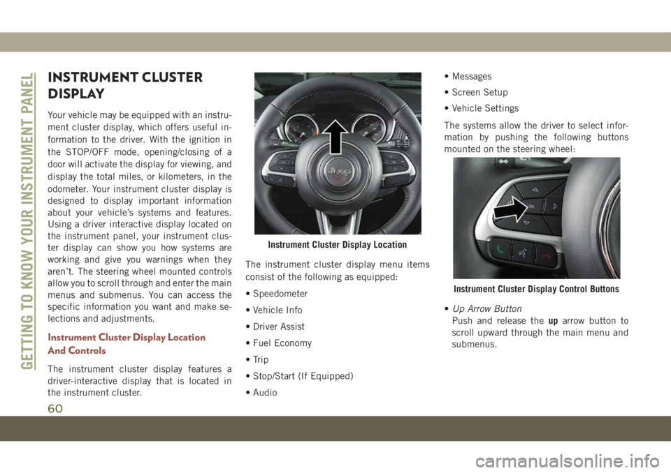
The instrument cluster display features a
driver-interactive display that is located in
the instrument cluster.The instrument cluster display menu items
consist of the following as equipped:
ŌĆó Speedometer
ŌĆó Vehicle Info
ŌĆó Driver Assist
ŌĆó Fuel Economy
ŌĆó Trip
ŌĆó Stop/Start (If Equipped)
ŌĆó AudioŌĆó Messages
ŌĆó Screen Setup
ŌĆó Vehicle Settings
The systems allow the driver to select infor-
mation by pushing the following buttons
mounted on the steering wheel:
ŌĆóUp Arrow Button
Push and release theuparrow button to
scroll upward through the main menu and
submenus.
Instrument Cluster Display Location
Instrument Cluster Display Control Buttons
GETTING TO KNOW YOUR INSTRUMENT PANEL
60
Page 68 of 362
ŌĆö Battery Charge Warning Light
This warning light will illuminate when the
battery is not charging properly. If it stays on
while the engine is running, there may be a
malfunction with the charging system. Con-
tact an authorized dealer as soon as possible.
This indicates a possible problem with the
electrical system or a related component.
ŌĆö Door Open Warning Light
This indicator will illuminate when a door is
ajar/open and not fully closed.
NOTE:
If the vehicle is moving, there will also be a
single chime.
ŌĆö Electric Power Steering Fault
Warning Light
This warning light will turn on when there's a
fault with the EPS (Electric Power Steering)
system. Refer to ŌĆ£Power SteeringŌĆØ in ŌĆ£Start-
ing And OperatingŌĆØ in the OwnerŌĆÖs Manual for
further information.
WARNING!
Continued operation with reduced assist
could pose a safety risk to yourself and
others. Service should be obtained as soon
as possible.
ŌĆö Electronic Throttle Control (ETC)
Warning Light
This warning light will illuminate to indicate
a problem with the Electronic Throttle Con-
trol (ETC) system. If a problem is detected
while the vehicle is running, the light will
either stay on or flash depending on the
nature of the problem. Cycle the ignition
when the vehicle is safely and completely
stopped and the transmission is placed in the
PARK position. The light should turn off. If
the light remains on with the vehicle running,
your vehicle will usually be drivable; however,
see an authorized dealer for service as soon
as possible.
NOTE:
This light may turn on if the accelerator and
brake pedals are pressed at the same time.If the light continues to flash when the ve-
hicle is running, immediate service is re-
quired and you may experience reduced per-
formance, an elevated/rough idle, or engine
stall and your vehicle may require towing.
The light will come on when the ignition is
placed in the ON/RUN or ACC/ON/RUN posi-
tion and remain on briefly as a bulb check. If
the light does not come on during starting,
have the system checked by an authorized
dealer.
ŌĆö Engine Temperature Warning Light
This warning light will illuminate to warn of
an overheated engine condition. If the engine
coolant temperature is too high, this light will
illuminate and a single chime will sound.
If the light turns on while driving, safely pull
over and stop the vehicle. If the A/C system is
on, turn it off. Also, shift the transmission
into NEUTRAL and idle the vehicle. If the
temperature reading does not return to nor-
mal, turn the engine off immediately and call
for service.
Refer to ŌĆ£If Your Engine OverheatsŌĆØ in ŌĆ£In
Case Of EmergencyŌĆØ for further information.
GETTING TO KNOW YOUR INSTRUMENT PANEL
66
Page 73 of 362
CAUTION!
Do not continue driving with one or more
flat tires as handling may be compro-
mised. Stop the vehicle, avoiding sharp
braking and steering. If a tire puncture
occurs, repair immediately using the dedi-
cated tire repair kit and contact an autho-
rized dealer as soon as possible.
Each tire, including the spare (if provided),
should be checked monthly when cold and
inflated to the inflation pressure recom-
mended by the vehicle manufacturer on the
vehicle placard or tire inflation pressure la-
bel. (If your vehicle has tires of a different
size than the size indicated on the vehicle
placard or tire inflation pressure label, you
should determine the proper tire inflation
pressure for those tires.)
As an added safety feature, your vehicle has
been equipped with a Tire Pressure Monitor-
ing System (TPMS) that illuminates a low tire
pressure telltale when one or more of your
tires is significantly under-inflated. Accord-
ingly, when the low tire pressure telltale illu-
minates, you should stop and check your tiresas soon as possible, and inflate them to the
proper pressure. Driving on a significantly
under-inflated tire causes the tire to overheat
and can lead to tire failure. Under-inflation
also reduces fuel efficiency and tire tread
life, and may affect the vehicleŌĆÖs handling
and stopping ability.
Please note that the TPMS is not a substitute
for proper tire maintenance, and it is the
driverŌĆÖs responsibility to maintain correct tire
pressure, even if under-inflation has not
reached the level to trigger illumination of the
TPMS low tire pressure telltale.
Your vehicle has also been equipped with a
TPMS malfunction indicator to indicate when
the system is not operating properly. The
TPMS malfunction indicator is combined
with the low tire pressure telltale. When the
system detects a malfunction, the telltale will
flash for approximately one minute and then
remain continuously illuminated. This se-
quence will continue upon subsequent ve-
hicle start-ups as long as the malfunction
exists. When the malfunction indicator is
illuminated, the system may not be able to
detect or signal low tire pressure as intended.
TPMS malfunctions may occur for a variety of
reasons, including the installation of replace-
ment or alternate tires or wheels on the vehicle
that prevent the TPMS from functioning prop-
erly. Always check the TPMS malfunction tell-
tale after replacing one or more tires or wheels
on your vehicle to ensure that the replacement
or alternate tires and wheels allow the TPMS to
continue to function properly.
CAUTION!
The TPMS has been optimized for the origi-
nal equipment tires and wheels. TPMS pres-
sures and warning have been established for
the tire size equipped on your vehicle. Un-
desirable system operation or sensor damage
may result when using replacement equip-
ment that is not of the same size, type,
and/or style. Aftermarket wheels can cause
sensor damage. Using aftermarket tire seal-
ants may cause the Tire Pressure Monitoring
System (TPMS) sensor to become inoper-
able. After using an aftermarket tire sealant
it is recommended that you take your vehicle
to your authorized dealer to have your sensor
function checked.
71
Page 81 of 362
SAFETY FEATURES
Anti-Lock Brake System (ABS)
The Anti-Lock Brake System (ABS) provides
increased vehicle stability and brake perfor-
mance under most braking conditions. The
system automatically prevents wheel lock,
and enhances vehicle control during braking.
The ABS performs a self-check cycle to en-
sure that the ABS is working properly each
time the vehicle is started and driven. During
this self-check, you may hear a slight clicking
sound as well as some related motor noises.
ABS is activated during braking when the
system detects one or more wheels begin to
lock. Road conditions such as ice, snow,
gravel, bumps, railroad tracks, loose debris,
or panic stops may increase the likelihood of
ABS activation(s).
You also may experience the following when
ABS activates:
ŌĆó The ABS motor noise (it may continue to
run for a short time after the stop).
ŌĆó The clicking sound of solenoid valves.ŌĆó Brake pedal pulsations.
ŌĆó A slight drop of the brake pedal at the end
of the stop.
These are all normal characteristics of ABS.
WARNING!
ŌĆó The ABS contains sophisticated elec-
tronic equipment that may be suscep-
tible to interference caused by improp-
erly installed or high output radio
transmitting equipment. This interfer-
ence can cause possible loss of anti-lock
braking capability. Installation of such
equipment should be performed by
qualified professionals.
ŌĆó Pumping of the Anti-Lock Brakes will
diminish their effectiveness and may
lead to a collision. Pumping makes the
stopping distance longer. Just press
firmly on your brake pedal when you
need to slow down or stop.
ŌĆó The ABS cannot prevent the natural laws
of physics from acting on the vehicle,
nor can it increase braking or steering
efficiency beyond that afforded by the
WARNING!
condition of the vehicle brakes and tires
or the traction afforded.
ŌĆó The ABS cannot prevent collisions, in-
cluding those resulting from excessive
speed in turns, following another vehicle
too closely, or hydroplaning.
ŌĆó The capabilities of an ABS equipped
vehicle must never be exploited in a
reckless or dangerous manner that could
jeopardize the userŌĆÖs safety or the safety
of others.
ABS is designed to function with the OEM
tires. Modification may result in degraded
ABS performance.
Anti-Lock Brake Warning Light
The yellow ŌĆ£Anti-Lock Brake Warning LightŌĆØ
will turn on when the ignition is turned to the
ON/RUN mode and may stay on for as long as
four seconds.
If the ŌĆ£Anti-Lock Brake Warning LightŌĆØ re-
mains on or comes on while driving, it indi-
cates that the anti-lock portion of the brake
system is not functioning and that service is
79
Page 83 of 362
WARNING!
speed in turns, driving on very slippery
surfaces, or hydroplaning. The capabilities
of a BAS-equipped vehicle must never be
exploited in a reckless or dangerous man-
ner, which could jeopardize the user's
safety or the safety of others.
Brake System Warning Light
The red ŌĆ£Brake System Warning LightŌĆØ will
turn on when the ignition is turned to the
ON/RUN mode and may stay on for as long as
four seconds.
If the ŌĆ£Brake System Warning LightŌĆØ remains
on or comes on while driving, it indicates that
the brake system is not functioning properly
and that immediate service is required. If the
ŌĆ£Brake System Warning LightŌĆØ does not
come on when the ignition is turned to the
ON/RUN mode, have the light repaired as
soon as possible.
Dynamic Steering Torque (DST)
Dynamic Steering Torque is a feature of the
ESC and Electric Power Steering (EPS) mod-
ules that provides torque at the steering
wheel for certain driving conditions in which
the ESC module is detecting vehicle instabil-
ity. The torque that the steering wheel re-
ceives is only meant to help the driver realize
optimal steering behavior in order to reach/
maintain vehicle stability. The only notifica-
tion the driver receives that the feature is
active is the torque applied to the steering
wheel.
NOTE:
The DST feature is only meant to help the
driver realize the correct course of action
through small torques on the steering wheel,
which means the effectiveness of the DST
feature is highly dependent on the driverŌĆÖs
sensitivity and overall reaction to the applied
torque. It is very important to realize that this
feature will not steer the vehicle, meaning the
driver is still responsible for steering the
vehicle.
Electronic Brake Force Distribution (EBD)
This function manages the distribution of the
braking torque between the front and rear
axles by limiting braking pressure to the rear
axle. This is done to prevent overslip of the
rear wheels to avoid vehicle instability, and to
prevent the rear axle from entering ABS be-
fore the front axle.
Electronic Roll Mitigation (ERM)
This system anticipates the potential for
wheel lift by monitoring the driverŌĆÖs steering
wheel input and the speed of the vehicle.
When ERM determines that the rate of
change of the steering wheel angle and vehi-
cleŌĆÖs speed are sufficient to potentially cause
wheel lift, it then applies the appropriate
brake and may also reduce engine power to
lessen the chance that wheel lift will occur.
ERM can only reduce the chance of wheel lift
occurring during severe or evasive driving
maneuvers; it cannot prevent wheel lift due to
other factors, such as road conditions, leav-
ing the roadway, or striking objects or other
vehicles.
81
Page 84 of 362
WARNING!
Many factors, such as vehicle loading,
road conditions and driving conditions,
influence the chance that wheel lift or
rollover may occur. ERM cannot prevent
all wheel lift or roll overs, especially those
that involve leaving the roadway or striking
objects or other vehicles. The capabilities
of an ERM-equipped vehicle must never
be exploited in a reckless or dangerous
manner which could jeopardize the user's
safety or the safety of others.
Electronic Stability Control (ESC)
This system enhances directional control and
stability of the vehicle under various driving
conditions. ESC corrects for oversteering or
understeering of the vehicle by applying the
brake of the appropriate wheel(s) to assist in
counteracting the oversteer or understeer
condition. Engine power may also be reduced
to help the vehicle maintain the desired path.
ESC uses sensors in the vehicle to determine
the vehicle path intended by the driver and
compares it to the actual path of the vehicle.When the actual path does not match the
intended path, ESC applies the brake of the
appropriate wheel to assist in counteracting
the oversteer or understeer condition.
ŌĆó Oversteer ŌĆö when the vehicle is turning
more than appropriate for the steering
wheel position.
ŌĆó Understeer ŌĆö when the vehicle is turning
less than appropriate for the steering wheel
position.
The ŌĆ£ESC Activation/Malfunction Indicator
LightŌĆØ located in the instrument cluster will
start to flash as soon as the ESC system
becomes active. The ŌĆ£ESC Activation/
Malfunction Indicator LightŌĆØ also flashes
when the TCS is active. If the ŌĆ£ESC
Activation/Malfunction Indicator LightŌĆØ be-
gins to flash during acceleration, ease up on
the accelerator and apply as little throttle as
possible. Be sure to adapt your speed and
driving to the prevailing road conditions.
WARNING!
ŌĆó Electronic Stability Control (ESC) can-
not prevent the natural laws of physics
from acting on the vehicle, nor can it
increase the traction afforded by prevail-
ing road conditions. ESC cannot prevent
accidents, including those resulting
from excessive speed in turns, driving on
very slippery surfaces, or hydroplaning.
ESC also cannot prevent accidents re-
sulting from loss of vehicle control due
to inappropriate driver input for the con-
ditions. Only a safe, attentive, and skill-
ful driver can prevent accidents. The
capabilities of an ESC equipped vehicle
must never be exploited in a reckless or
dangerous manner which could jeopar-
dize the userŌĆÖs safety or the safety of
others.
ŌĆó Vehicle modifications, or failure to prop-
erly maintain your vehicle, may change
the handling characteristics of your ve-
hicle, and may negatively affect the per-
formance of the ESC system. Changes to
the steering system, suspension, brak-
SAFETY
82
Page 94 of 362
NOTE:
FCW monitors the information from the for-
ward looking sensors as well as the Electronic
Brake Controller (EBC), to calculate the prob-
ability of a forward collision. When the sys-
tem determines that a forward collision is
probable, the driver will be provided with
audible and visual warnings and may provide
a brake jerk warning.
If the driver does not take action based upon
these progressive warnings, then the system
will provide a limited level of active braking to
help slow the vehicle and mitigate the poten-
tial forward collision. If the driver reacts to
the warnings by braking and the system de-
termines that the driver intends to avoid the
collision by braking but has not applied suf-
ficient brake force, the system will compen-
sate and provide additional brake force as
required.
If a Forward Collision Warning with Mitigation
event begins at a speed below 26 mph
(42 km/h), the system may provide the maxi-
mum braking possible to mitigate the poten-
tial forward collision. If the Forward CollisionWarning with Mitigation event stops the ve-
hicle completely, the system will hold the
vehicle at standstill for two seconds and then
release the brakes.
When the system determines a collision with
the vehicle in front of you is no longer prob-
able, the warning message will be deacti-
vated.
NOTE:
ŌĆó The minimum speed for FCW activation is
1 mph (2 km/h).
ŌĆó The FCW alerts may be triggered on objects
other than vehicles such as guard rails or
sign posts based on the course prediction.
This is expected and is a part of normal
FCW activation and functionality.
ŌĆó It is unsafe to test the FCW system. To
prevent such misuse of the system, after
four Active Braking events within a key
cycle, the Active Braking portion of FCW
will be deactivated until the next key cycle.ŌĆó The FCW system is intended for on-road
use only. If the vehicle is taken off-road, the
FCW system should be deactivated to pre-
vent unnecessary warnings to the
surroundings.
WARNING!
Forward Collision Warning (FCW) is not
intended to avoid a collision on its own,
nor can FCW detect every type of potential
collision. The driver has the responsibility
to avoid a collision by controlling the ve-
hicle via braking and steering. Failure to
follow this warning could lead to serious
injury or death.
FCW Settings
The forward collision menu setting is located
in the Uconnect settings.
NOTE:
The default status of FCW is ŌĆ£Full On,ŌĆØ this
allows the system to provide warning and
autonomous braking in the event of a poten-
tial frontal collision.
SAFETY
92
Page 109 of 362
Your vehicle may be equipped with the follow-
ing Air Bag System Components:
Air Bag System Components
ŌĆó Occupant Restraint Controller (ORC)
ŌĆó Air Bag Warning Light
ŌĆó Steering Wheel and Column
ŌĆó Instrument Panel
ŌĆó Knee Impact Bolsters
ŌĆó Driver and Front Passenger Air Bags
ŌĆó Seat Belt Buckle Switch
ŌĆó Supplemental Side Air Bags
ŌĆó Front and Side Impact Sensors
ŌĆó Seat Belt Pretensioners
ŌĆó Seat Track Position Sensors
Air Bag Warning Light
The ORC monitors the readiness of the
electronic parts of the air bag system when-
ever the ignition switch is in the START or
ON/RUN position. If the ignition switch is in
the OFF position or in the ACC position, the
air bag system is not on and the air bags will
not inflate.The ORC contains a backup power supply
system that may deploy the air bag system
even if the battery loses power or it becomes
disconnected prior to deployment.
The ORC turns on the Air Bag Warning Light
in the instrument panel for approximately
four to eight seconds for a self-check when
the ignition switch is first in the ON/RUN
position. After the self-check, the Air Bag
Warning Light will turn off. If the ORC detects
a malfunction in any part of the system, it
turns on the Air Bag Warning Light, either
momentarily or continuously. A single chime
will sound to alert you if the light comes on
again after initial startup.
The ORC also includes diagnostics that will
illuminate the instrument panel Air Bag
Warning Light if a malfunction is detected
that could affect the air bag system. The
diagnostics also record the nature of the
malfunction. While the air bag system is
designed to be maintenance free, if any of the
following occurs, have an authorized dealer
service the air bag system immediately.ŌĆó
The Air Bag Warning Light does not come on
during the four to eight seconds when the
ignition switch is first in the ON/RUN position.
ŌĆó The Air Bag Warning Light remains on after
the four to eight-second interval.
ŌĆó The Air Bag Warning Light comes on inter-
mittently or remains on while driving.
NOTE:
If the speedometer, tachometer, or any en-
gine related gauges are not working, the Oc-
cupant Restraint Controller (ORC) may also
be disabled. In this condition the air bags
may not be ready to inflate for your protec-
tion. Have an authorized dealer service the air
bag system immediately.
WARNING!
Ignoring the Air Bag Warning Light in your
instrument panel could mean you wonŌĆÖt have
the air bag system to protect you in a collision.
If the light does not come on as a bulb check
when the ignition is first turned on, stays on
after you start the vehicle, or if it comes on as
you drive, have an authorized dealer service
the air bag system immediately.
107
Page 110 of 362
Redundant Air Bag Warning Light
If a fault with the Air Bag Warning Light is
detected, which could affect the Supplemen-
tal Restraint System (SRS), the Redundant
Air Bag Warning Light will illuminate on the
instrument panel. The Redundant Air Bag
Warning Light will stay on until the fault is
cleared. In addition, a single chime will
sound to alert you that the Redundant Air Bag
Warning Light has come on and a fault has
been detected. If the Redundant Air Bag
Warning Light comes on intermittently or
remains on while driving have an authorized
dealer service the vehicle immediately.
For additional information regarding the Re-
dundant Air Bag Warning Light refer to ŌĆ£Get-
ting To Know Your Instrument PanelŌĆØ section
of this manual.
Front Air Bags
This vehicle has front air bags and lap/
shoulder belts for both the driver and front
passenger. The front air bags are a supple-
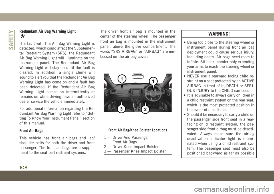
ment to the seat belt restraint systems.The driver front air bag is mounted in the
center of the steering wheel. The passenger
front air bag is mounted in the instrument
panel, above the glove compartment. The
words ŌĆ£SRS AIRBAGŌĆØ or ŌĆ£AIRBAGŌĆØ are em-
bossed on the air bag covers.
WARNING!
ŌĆó Being too close to the steering wheel or
instrument panel during front air bag
deployment could cause serious injury,
including death. Air bags need room to
inflate. Sit back, comfortably extending
your arms to reach the steering wheel or
instrument panel.
ŌĆó NEVER use a rearward facing child re-
straint on a seat protected by an ACTIVE
AIRBAG in front of it, DEATH or SERI-
OUS INJURY to the CHILD can occur.
ŌĆó It is advisable to always carry children in
a child restraint system on the rear seat,
which is the most protected position in
the event of a collision.
ŌĆó Should it be necessary to carry a child on
the passenger side front seat in a rear-
facing child restraint system, the pas-
senger side front airbag must be deacti-
vated. Always make sure the airbag
deactivation indicator light is illumi-
nated when using a child restraint sys-
tem. The passenger seat must also be
positioned backward as far as possible
Front Air Bag/Knee Bolster Locations
1 ŌĆö Driver And Passenger
Front Air Bags
2 ŌĆö Driver Knee Impact Bolster
3 ŌĆö Passenger Knee Impact Bolster
SAFETY
108