warning light JEEP COMPASS 2019 Owner handbook (in English)
[x] Cancel search | Manufacturer: JEEP, Model Year: 2019, Model line: COMPASS, Model: JEEP COMPASS 2019Pages: 362, PDF Size: 6.23 MB
Page 167 of 362
ADAPTIVE CRUISE
CONTROL (ACC) —
IF EQUIPPEDACC will allow you to keep cruise control
engaged in light to moderate traffic condi-
tions without the constant need to reset your
cruise control. ACC utilizes a radar sensor
and a forward facing camera designed to
detect a vehicle directly ahead of you.
NOTE:
• If the sensor does not detect a vehicle
ahead of you, ACC will maintain a fixed set
speed.
• If the ACC sensor detects a vehicle ahead,
ACC will apply limited braking or accelera-
tion (not to exceed the original set speed)
automatically to maintain a preset follow-
ing distance, while matching the speed of
the vehicle ahead.
To Activate/Deactivate
Push and release the Adaptive Cruise Control
(ACC) on/off button. The ACC menu in the
instrument cluster display will read “ACC
Ready.”To turn the system off, push and release the
Adaptive Cruise Control (ACC) on/off button
again. At this time, the system will turn off
and the instrument cluster display will read
“Adaptive Cruise Control (ACC) Off.”
WARNING!
Leaving the Adaptive Cruise Control (ACC)
system on when not in use is dangerous.
You could accidentally set the system or
cause it to go faster than you want. You
could lose control and have a collision.
Always leave the system off when you are
not using it.
To Set A Desired ACC Speed
When the vehicle reaches the speed desired,
push the SET(+)button or the SET(-)button
and release. The instrument cluster display
will show the set speed.
If the system is set when the vehicle speed is
below 19 mph (30 km/h), the set speed shall
be defaulted to 19 mph (30 km/h). If the
system is set when the vehicle speed is above
19 mph (30 km/h), the set speed shall be the
current speed of the vehicle.
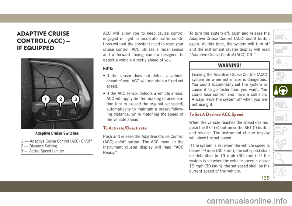
Adaptive Cruise Switches
1—Adaptive Cruise Control (ACC) On/Off
2 — Distance Setting
3 — Active Speed Limiter
165
Page 183 of 362
7. Remove the fuel nozzle and close the fuel
door.
Emergency Gas Can Refueling
Most gas cans will not open the flapper door.
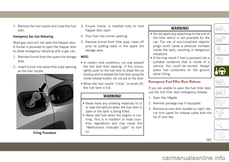
A funnel is provided to open the flapper door
to allow emergency refueling with a gas can.
1. Retrieve funnel from the spare tire storage
area.
2. Insert funnel into same filler pipe opening
as the fuel nozzle.3. Ensure funnel is inserted fully to hold
flapper door open.
4. Pour fuel into funnel opening.
5. Remove funnel from filler pipe, clean off
prior to putting back in the spare tire
storage area.
NOTE:
•
In certain cold conditions, ice may prevent
the fuel door from opening. If this occurs,
lightly push on the fuel door to break the ice
buildup and re-release the fuel door using the
inside release button. Do not pry on the door.
• When the fuel nozzle “clicks” or shuts off,
the fuel tank is full.
WARNING!
• Never have any smoking materials lit in
or near the vehicle when the fuel door is
open or the tank is being filled.
• Never add fuel when the engine is run-
ning. This is in violation of most coun-
tries regulations and may cause the
“Malfunction Indicator Light” to turn
on.
WARNING!
• Do not apply any object/cap to the end of
the filler which is not provided for the
car. The use of non-compliant objects/
plugs could cause a pressure increase
inside the tank, resulting in dangerous
situations.
• A fire may result if fuel is pumped into a
portable container that is inside of a
vehicle. You could be burned. Always
place fuel containers on the ground
while filling.
Emergency Fuel Filler Door Release
If you are unable to open the fuel filler door,
use the fuel filler door emergency release.
1. Open the liftgate.
2. Remove package tray if equipped.
3. Remove access door located on right inte-
rior trim panel for release cable with the
tip of your key.
Filling Procedure
181
Page 186 of 362
Emergency Gas Can Refueling
Most gas cans will not open the flapper door.
A funnel is provided to open the flapper door
to allow emergency refueling with a gas can.
1. Retrieve funnel from the rear cargo area.
2. Insert funnel into same filler pipe opening
as the fuel nozzle.
3. Ensure funnel is inserted fully to hold
flapper door open.
4. Pour fuel into funnel opening.
5. Remove funnel from filler pipe, clean off
prior to putting back in the spare tire
storage area.
NOTE:
• When the fuel nozzle “clicks” or shuts off,
the fuel tank is full.WARNING!
• Never have any smoking materials lit in
or near the vehicle when the fuel door is
open or the tank is being filled.
• Never add fuel when the engine is run-
ning. This is in violation of most coun-
tries regulations and may cause the
“Malfunction Indicator Light” to turn
on.
• Do not apply any object/cap to the end of
the filler which is not provided for the
car. The use of non-compliant objects/
plugs could cause a pressure increase
inside the tank, resulting in dangerous
situations.
• A fire may result if fuel is pumped into a
portable container that is inside of a
vehicle. You could be burned. Always
place fuel containers on the ground
while filling.
Adblue (UREA) — If Equipped
The vehicle is equipped with an UREA injec-
tion system and Selective Catalytic Reduc-
tion to meet emission standards. These two
systems ensure compliance with the diesel
emissions requirements; at the same, they
ensure fuel-efficiency, handling, torque and
power. For messages and system warnings,
refer to the "Warning Lights And Messages" in
the "Getting To Know Your Instrument Panel"
section. AdBlue (UREA) is a very stable prod-
uct with a long shelf life. Stored at tempera-
tures LOWER than 90 °F (32 °C), it has a
shelf life of at least one year. For more infor-
mation on the AdBlue liquid type, see the
“Fluids and lubricants” in the “Technical
specifications” section. The vehicle is
equipped with an automatic AdBlue heating
system when the engine starts allowing the
system to work correctly at temperatures
lower than 12 °F (-11 °C).
NOTE:
AdBlue freezes at temperatures lower than
12 °F (-11 °C).
STARTING AND OPERATING
184
Page 188 of 362
Proceed as follows:
• Insert the AdBlue (UREA) nozzle in the
filler, start refilling and stop refilling at the
first shut-off (the shut-off indicates that the
AdBlue (UREA) tank is full). Do not pro-
ceed with the refilling, to prevent spillage
of AdBlue (UREA).
• Extract the nozzle.
Refilling With Containers
Proceed as follows:
• Check the expiration date.
• Read the advice for use on the label before
pouring the content of the bottle into the
AdBlue (UREA) tank.
• If systems which cannot be screwed in (e.g.
tanks) are used for refilling, after the indi-
cation appears on the instrument panel
display refer to “Warning lights And Mes-
sages" in the “Getting To Know Your Instru-
ment Panel” for further information, fill the
AdBlue (UREA) tank with no more than
2 Gallons (8 liters).• If containers which can be screwed to the
filler are used, the reservoir is full when the
AdBlue (UREA) level in the container stops
pouring out. Do not proceed further.
Operations After Refilling
Proceed as follows:
• Fit the cap back on the AdBlue (UREA)
filler by turning it clockwise and screwing it
completely.
• Cycle the ignition to RUN (it is not neces-
sary to start the engine).
• Wait for the indication on the instrument
panel to switch off before moving the car.
The indication may stay on for a few sec-
onds to approximately half a minute. If the
engine is started and the car is moved, the
indication will remain on for longer. This
will not compromise engine operation.
• If the AdBlue (UREA) was topped up when
the tank was empty, wait for 2 minutes
before starting the engine.NOTE:
• If AdBlue (UREA) is spilled out of the filler
neck, clean up well the area and proceed to
filling up again. If the liquid crystallizes,
eliminate it with a sponge and warm water.
• DO NOT EXCEED THE MAXIMUM LEVEL:
this could cause damage to the reservoir.
AdBlue (UREA) freezes at under 12° F
(-11° C). Although the system is designed
to operate below the freezing point of the
UREA, it is advisable not to fill the tank
beyond the maximum level because if the
UREA freezes the system can be damaged.
Follow the instructions in this section.
• If the AdBlue (UREA) is spilled on painted
surfaces or aluminium, immediately clean
the area with water and use absorbent ma-
terial to collect the fluid that has been
spilled on the ground.
•
Do not try to start the engine if AdBlue
(UREA) was accidentally added to the diesel
fuel tank, this can result in serious engine
damage, contact an authorized dealer.
•Do not add additives or other fluids to AdBlue
(UREA), doing so could damage the system.
STARTING AND OPERATING
186
Page 189 of 362
• The use of non-conforming or degraded
AdBlue (UREA) may lead to indications
appearing on the instrument panel display
refer to “Warning Lights And Messages" in
the “Getting To Know Your Instrument
Panel” for further information.
• Never pour AdBlue (UREA) into another
container: it could be contaminated.
• If the AdBlue (UREA) runs out, see refer to
“Warning Lights And Messages" in the
“Getting To Know Your Instrument Panel”
for further information to continue using
the car normally.
TRAILER TOWING
Common Towing Definitions
The following trailer towing related defini-
tions will assist you in understanding the
following information:
Gross Vehicle Weight Rating (GVWR)
The GVWR is the total allowable weight of
your vehicle. This includes driver, passen-
gers, cargo and tongue weight.
The total load must be limited so that you do
not exceed the GVWR. Refer to “Vehicle
Loading/Vehicle Certification Label” in “Start-
ing And Operating” for further information.
Gross Trailer Weight (GTW)
The GTW is the weight of the trailer plus the
weight of all cargo, consumables and equip-
ment (permanent or temporary) loaded in or
on the trailer in its "loaded and ready for
operation" condition.
The recommended way to measure GTW is to
put your fully loaded trailer on a vehicle
scale. The entire weight of the trailer must be
supported by the scale.
Gross Axle Weight Rating (GAWR)
The GAWR is the maximum capacity of the
front and rear axles. Distribute the load over
the front and rear axles evenly. Make sure
that you do not exceed either front or rear
GAWR. Refer to “Vehicle Loading/Vehicle
Certification Label” in “Starting And Operat-
ing” for further information.
WARNING!
It is important that you do not exceed the
maximum front or rear GAWR. A dangerous
driving condition can result if either rating
is exceeded. You could lose control of the
vehicle and have a collision.
Tongue Weight (TW)
The tongue weight is the downward force
exerted on the hitch ball by the trailer. You
must consider this as part of the load on your
vehicle.
Trailer Frontal Area
The frontal area is the maximum height mul-
tiplied by the maximum width of the front of
a trailer.
187
Page 195 of 362
HAZARD WARNING
FLASHERS
The Hazard Warning flasher switch is located
in the lower center area of the instrument
panel.
Push the switch to turn on the
Hazard Warning flasher. When the
switch is activated, all directional
turn signals will flash on and off to
warn oncoming traffic of an emergency. Push
the switch a second time to turn off the
Hazard Warning flashers.This is an emergency warning system and it
should not be used when the vehicle is in
motion. Use it when your vehicle is disabled
and it is creating a safety hazard for other
motorists.
When you must leave the vehicle to seek
assistance, the Hazard Warning flashers will
continue to operate even though the ignition
is placed in the OFF position.
NOTE:
With extended use, the Hazard Warning
flashers may wear down your battery.
BULB REPLACEMENT
Replacement Bulbs
Interior Bulbs
Lamps Bulb Number
Front Courtesy Light C5W
Front Courtesy Lights (Sun Visors) C5W
Rear Dome Light (Models Without Retractable roof) C5W
Rear Interior Lights (Models With Retractable roof) C5W
Interior Lights HT-168
Dome Light (Glove Box) HT-168
193
Page 198 of 362
NOTE:
We advise referring to an authorized dealer.
WARNING!
Carry out the operation of replacing lamps
only with the engine off. Also make sure
that the engine is cold, to avoid the danger
of burns.
Turn Signal Light/Position Lights/
Daytime Running Lights
To replace the bulbs proceed as follows:
1. Turn the front wheels completely.
2. Remove the wheel liner.
3. Remove the electrical connectors.
4. For the DRL bulb, grip the bulb at the top
and bottom locking tabs and squeeze to
and remove the bulb.
5. To replace the DRL bulb gently push bulb
towards housing. Be sure to hear both the
top and bottom locking tabs “CLICK” to
ensure the bulb is properly seated.6. For the turn signal bulb, rotate in a coun-
terclockwise direction and remove the
bulb and bulb socket. Pull the bulb axially
to remove it from the socket.
7. Install the bulb and sockets and rotate
them clockwise making sure that it is
properly locked.
8. Reconnect the electrical connectors.
9. Reinstall the wheel liner.
NOTE:
We advise referring to an authorized dealer.
Front Fog Lights
To replace the bulbs proceed as follows:
1. Turn the front wheels completely.
2. Remove the wheel liner.
3. By pushing the electrical connector tab
remove the electrical connector.
4. Rotate the bulb counterclockwise, and
then replace the bulb.5. Insert the new bulb in the socket, making
sure the bulb is locked into place.
6. Reconnect the electrical connector.
7. Reinstall the wheel liner.
NOTE:
We advise referring to an authorized dealer.
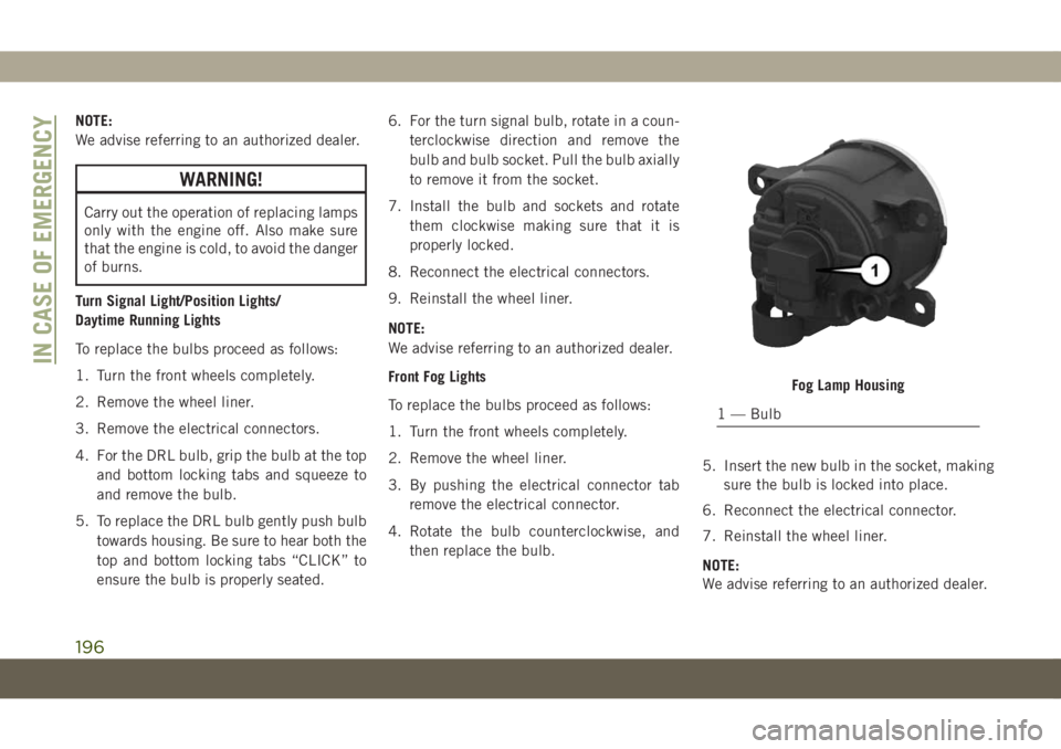
Fog Lamp Housing
1 — Bulb
IN CASE OF EMERGENCY
196
Page 201 of 362
Rear Fog Lamps
We advise referring to an authorized dealer
for service.
NOTE:
We advise referring to an authorized dealer.
Reverse Lamps
We advise referring to an authorized dealer
for service.
3rd Stop Lamp
The CHMSL is LED. For their replacement,
see an authorized dealer.
License Plate Lights
The license plate light is LED. For their re-
placement, see an authorized dealer.WARNING!
• Before proceeding with the replacement
of the lamp wait until the exhaust pipes
are cool: DANGER OF BURNS!
• Modifications or repair of the electrical
system performed incorrectly and with-
out taking into account the technical
characteristics can cause malfunctions
with the risk of fire.
• Halogen lamps contain gas under pres-
sure, in the event of breakage be careful
of the projection of fragments of glass.
• Halogen lamps must be handled by
touching only the metallic part. If the
transparent bulb is in contact with the
fingers, reduces the intensity of the
emitted light and you can also affect the
life of the lamp. In case of accidental
contact, rub the bulb with a cloth damp-
ened with alcohol and allow to dry.
NOTE:
It is recommended to have your bulbs re-
placed by an authorized dealer.
FUSES
WARNING!
• When replacing a blown fuse, always use
an appropriate replacement fuse with
the same amp rating as the original fuse.
Never replace a fuse with another fuse of
higher amp rating. Never replace a
blown fuse with metal wires or any other
material. Do not place a fuse inside a
circuit breaker cavity or vice versa. Fail-
ure to use proper fuses may result in
serious personal injury, fire and/or prop-
erty damage.
• Before replacing a fuse, make sure that
the ignition is off and that all the other
services are switched off and/or disen-
gaged.
• If the replaced fuse blows again, contact
an authorized dealer.
•
If a general protection fuse for safety
systems (air bag system, braking system),
power unit systems (engine system, trans-
mission system) or steering system blows,
contact an authorized dealer.
199
Page 214 of 362
5. Raise the vehicle just enough to remove
the flat tire.
WARNING!
Raising the vehicle higher than necessary
can make the vehicle less stable. It could
slip off the jack and hurt someone near it.
Raise the vehicle only enough to remove
the tire.
6. Remove the wheel bolts and tire.
7. Remove the alignment pin from the jack
assembly and thread the pin into the
wheel hub to assist in mounting the spare
tire.
8. Mount the spare tire.
CAUTION!
Be sure to mount the spare tire with the
valve stem facing outward. The vehicle
could be damaged if the spare tire is
mounted incorrectly.NOTE:
• For vehicles equipped, do not attempt
to install a center cap or wheel cover on
the compact spare.
• Refer to “Compact Spare Tire” and to
“Limited-Use Spare” under “Tires—
General Information” in “Servicing And
Maintenance” in the Owner's Manual
for additional warnings, cautions, and
information about the spare tire, its
use, and operation.
9. Install and lightly tighten the wheel bolts.
WARNING!
To avoid the risk of forcing the vehicle off
the jack, do not tighten the wheel nuts
fully until the vehicle has been lowered.
Failure to follow this warning may result in
serious injury.
10. Lower the vehicle to the ground by turn-
ing the jack handle counterclockwise.11. Finish tightening the wheel bolts. Push
down on the wrench while at the end of
the handle for increased leverage.
Tighten the wheel bolts in a star pattern
until each wheel bolt has been tightened
twice. Refer to “Wheel And Tire Torque
Specifications” in “Technical Specifica-
tions” for the proper lug bolt torque. If in
doubt about the correct tightness, have
them checked with a torque wrench by
an authorized dealer or at a service
station.
12. Place the jack on the foam tray and open
it far enough so that it is secured. Once
placed in position, rotate it clockwise to
lock it in. Replace the alignment pin in
the center hole to lock the jack in place.
WARNING!
A loose tire or jack thrown forward in a
collision or hard stop could endanger the
occupants of the vehicle. Always stow the
jack parts and the spare tire in the places
provided. Have the deflated (flat) tire re-
paired or replaced immediately.
IN CASE OF EMERGENCY
212
Page 215 of 362
Road Tire Installation
1. Mount the road tire on the axle.
2. Install the remaining wheel bolts with the
threaded end of the wheel bolt toward the
wheel. Lightly tighten the wheel bolts.
WARNING!
To avoid the risk of forcing the vehicle off
the jack, do not tighten the wheel bolts
fully until the vehicle has been lowered.
Failure to follow this warning may result in
serious injury.
3. Lower the vehicle to the ground by turning
the jack handle counterclockwise.
4. Finish tightening the wheel bolts. Push
down on the wrench while at the end of
the handle for increased leverage. Tighten
the wheel bolts in a star pattern until each
wheel bolt has been tightened twice. Re-
fer to “Wheel And Tire Torque Specifica-
tions” in “Technical Specifications” for
the proper lug bolt torque. If in doubt
about the correct tightness, have them
checked with a torque wrench by an au-
thorized dealer or service station.5. Lower the jack until it is free. Remove the
wheel blocks. Reassemble the lug wrench
to the jack assembly and stow it in the
spare tire area. Secure the assembly using
the means provided. Release the parking
brake before driving the vehicle.
6. After 25 miles (40 km), check the wheel
bolt torque with a torque wrench to ensure
that all wheel bolts are properly seated
against the wheel.
EC Declaration Of Conformance
1. The undersigned,Jaswant Singh, repre-
senting the Moonlight Tools Pvt. Ltd.,
herewith declares that the machinery de-
scribed below fulfills all the relevant pro-
visions of:
• The EC-directive 2006/42/EC on
Machinery2. Description of machinery.
a.
Generic Denomination:Pantograph jack
b.Function:Lifting Motor Vehicle
Model
CodeModel
NameType Working
load
M6 (556) MPV MLF1 1250Kg
3. Manufacturer Detail
Moonlight Tools Pvt. Ltd.
Vill. Jaspalon, G.T. Road Doraha
Distt. Ludhiana (141421) Punjab (India)
Teh. PH. No. 01628 258302
4. Authorized Person to compile the techni-
cal file
Mr. jaswant Singh DGM (QA & Dev.)
Moonlight Tools Pvt. Ltd.
Ludhiana
5. Reference standard : PF-90065
Date Place Signature Seal
29–03–
2017Doraha
Ludhiana
213