check oil JEEP COMPASS 2019 Owner handbook (in English)
[x] Cancel search | Manufacturer: JEEP, Model Year: 2019, Model line: COMPASS, Model: JEEP COMPASS 2019Pages: 362, PDF Size: 6.23 MB
Page 9 of 362
Power Inverter — If Equipped.......... 58
ROOF LUGGAGE RACK — IF EQUIPPED......... 59
GETTING TO KNOW YOUR
INSTRUMENT PANEL
INSTRUMENT CLUSTER DISPLAY............ 60Instrument Cluster Display Location
And Controls.................... 60
Oil Change Indicator System — If Equipped . 61
Gear Shift Indicator (GSI) — If Equipped . . . 61
Instrument Cluster Display Menu Items.... 62
Fuel System Messages.............. 62
TRIP COMPUTER..................... 64
WARNING LIGHTS AND MESSAGES.......... 64
Red Warning Lights................ 64
Yellow Warning Lights............... 68
Yellow Indicator Lights.............. 72
Green Indicator Lights.............. 74
White Indicator Lights.............. 75
Blue Indicator Lights............... 76
Gray Indicator Lights............... 76
ONBOARD DIAGNOSTIC SYSTEM — OBD II...... 76Onboard Diagnostic System (OBD II)
Cybersecurity.................... 77
EMISSIONS INSPECTION AND MAINTENANCE
PROGRAMS....................... 77
SAFETY
SAFETY FEATURES................... 79Anti-Lock Brake System (ABS)......... 79
Electronic Brake Control System........ 80
AUXILIARY DRIVING SYSTEMS............. 88Blind Spot Monitoring (BSM) — If Equipped . 88Forward Collision Warning (FCW)
With Mitigation — If Equipped......... 91
Tire Pressure Monitor System (TPMS)..... 94
OCCUPANT RESTRAINT SYSTEMS........... 98Occupant Restraint Systems Features..... 98
Important Safety Precautions.......... 98
Seat Belt Systems................ 99
Supplemental Restraint Systems (SRS) . . . 106
Child Restraints — Carrying
Children Safely................. 122
Transporting Pets................ 137
SAFETY TIPS..................... 138Transporting Passengers............ 138
Exhaust Gas................... 138
Safety Checks You Should Make Inside
The Vehicle.................... 138
Periodic Safety Checks You Should Make
Outside The Vehicle............... 140
STARTING AND OPERATING
STARTING THE ENGINE................ 141Normal Starting — Gasoline Engine..... 141
Stopping The Engine.............. 143
Normal Starting — Diesel Engine....... 143
PARK BRAKE...................... 145Electric Park Brake (EPB)........... 145
MANUAL TRANSMISSION — IF EQUIPPED...... 147Shifting...................... 148
Downshifting................... 149
Parking....................... 150
AUTOMATIC TRANSMISSION — IF EQUIPPED.... 151Ignition Park Interlock.............. 152
Brake/Transmission Shift Interlock System . 152
Nine-Speed Automatic Transmission..... 152
FOUR-WHEEL DRIVE OPERATION — IF EQUIPPED . . 158
Jeep Active Drive................. 158
SELEC-TERRAIN — IF EQUIPPED........... 160Mode Selection Guide.............. 160
STOP/START SYSTEM — IF EQUIPPED........ 161Operating Modes................. 161
Manual Activation / Deactivation....... 162
ACTIVE SPEED LIMITER — IF EQUIPPED....... 162Activation..................... 163
Exceeding The Set Speed............ 163
Deactivation.................... 163
SPEED CONTROL — IF EQUIPPED.......... 163To Activate.................... 164
To Set A Desired Speed............. 164
To Resume Speed................ 164
To Deactivate................... 164
ADAPTIVE CRUISE CONTROL (ACC) —
IF EQUIPPED...................... 165
To Activate/Deactivate.............. 165
To Set A Desired ACC Speed.......... 165
To Resume.................... 166
To Vary The Speed Setting........... 166
Setting The Following Distance In ACC.... 167
PARKSENSE REAR PARK ASSIST — IF EQUIPPED . . 168ParkSense Sensors................ 168
ParkSense Warning Display........... 168
Enabling And Disabling ParkSense...... 168
ParkSense System Usage Precautions.... 169
PARKSENSE FRONT AND REAR PARK ASSIST —
IF EQUIPPED...................... 170
ParkSense Sensors................ 170
Enabling And Disabling ParkSense...... 171
Side Distance Warning System......... 171
PARKSENSE ACTIVE PARK ASSIST SYSTEM —
IF EQUIPPED...................... 173
7
Page 10 of 362
Enabling And Disabling The ParkSense
Active Park Assist System........... 173
Exiting The Parking Space........... 174
LANESENSE — IF EQUIPPED............. 176LaneSense Operation.............. 176
Turning LaneSense On Or Off......... 177
LaneSense Warning Message.......... 177
Changing LaneSense Status.......... 179
PARKVIEW REAR BACK UP CAMERA —
IF EQUIPPED...................... 179
REFUELING THE VEHICLE............... 180
Emergency Fuel Filler Door Release..... 181
REFUELING THE VEHICLE — DIESEL ENGINE.... 183Adblue (UREA) — If Equipped........ 184
TRAILER TOWING................... 187Common Towing Definitions.......... 187
Trailer Towing Weights (Maximum
Trailer Weight Ratings)............. 189
Towing Requirements.............. 189
RECREATIONAL TOWING (BEHIND MOTORHOME,
ETC.).......................... 191
Towing This Vehicle Behind Another
Vehicle....................... 191
Recreational Towing — Front-Wheel Drive (FWD)
Models....................... 191
Recreational Towing — 4X4 Models..... 192
IN CASE OF EMERGENCY
HAZARD WARNING FLASHERS............ 193
BULB REPLACEMENT................. 193
Replacement Bulbs............... 193
Replacing Exterior Bulbs............ 195
FUSES......................... 199General Information............... 200Fuse Location................... 200
Engine Compartment Fuses/Distribution
Unit........................ 200
Engine Compartment Fuses/Auxiliary Unit . . 204
Interior Fuses................... 205
Rear Cargo Fuse/Relay Distribution Unit . . . 206
JACKING AND TIRE CHANGING............ 208Jack Location/Spare Tire Stowage....... 208
Preparations For Jacking............ 209
Jacking Instructions............... 210
Road Tire Installation.............. 213
EC Declaration Of Conformance........ 213
Jack Usage Precautions............ 214
TIRE SERVICE KIT — IF EQUIPPED.......... 215
JUMP STARTING.................... 220
Preparations For Jump Start.......... 221
Jump Starting Procedure............ 222
REFUELING IN EMERGENCY.............. 223
IF YOUR ENGINE OVERHEATS............. 223
GEAR SELECTOR OVERRIDE.............. 224
FREEING A STUCK VEHICLE.............. 225
TOWING A DISABLED VEHICLE............ 226
Without The Key Fob.............. 227
Front-Wheel Drive (FWD) Models —
WithKeyFob ................... 227
4x4 Models.................... 227
Emergency Tow Hooks.............. 228
Tow Eye Usage — If Equipped......... 229
ENHANCED ACCIDENT RESPONSE SYSTEM (EARS) . 230
EVENT DATA RECORDER (EDR)............ 230
SERVICING AND MAINTENANCE
SCHEDULED SERVICING................ 2311.4L Gasoline Engine.............. 231Diesel Engines.................. 235
ENGINE COMPARTMENT............... 2401.4L Engine.................... 240
2.0L Diesel Engine............... 241
1.6L Diesel Engine............... 242
Checking Oil Level................ 243
Adding Washer Fluid.............. 243
Maintenance-Free Battery........... 244
DEALER SERVICE................... 245Air Conditioner Maintenance.......... 245
Wiper Blades................... 245
Exhaust System................. 246
Cooling System.................. 247
Brake System.................. 248
Manual Transmission — If Equipped..... 249
Automatic Transmission............. 249
RAISING THE VEHICLE................. 250
TIRES.......................... 250
Tires — General Information......... 250
Tire Types..................... 255
Spare Tires — If Equipped.......... 256
Tire Chains (Traction Devices)......... 257
Tire Rotation Recommendations........ 258
STORING THE VEHICLE................ 259
BODYWORK....................... 260
Preserving The Bodywork............ 260
INTERIORS....................... 261Seats And Fabric Parts............. 261
Plastic And Coated Parts............ 262
Leather Parts................... 262
Glass Surfaces.................. 262
TECHNICAL SPECIFICATIONS
IDENTIFICATION DATA................. 263Vehicle Identification Number......... 263
TABLE OF CONTENTS
8
Page 69 of 362
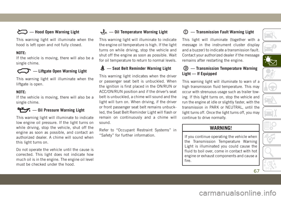
— Hood Open Warning Light
This warning light will illuminate when the
hood is left open and not fully closed.
NOTE:
If the vehicle is moving, there will also be a
single chime.
— Liftgate Open Warning Light
This warning light will illuminate when the
liftgate is open.
NOTE:
If the vehicle is moving, there will also be a
single chime.
— Oil Pressure Warning Light
This warning light will illuminate to indicate
low engine oil pressure. If the light turns on
while driving, stop the vehicle, shut off the
engine as soon as possible, and contact an
authorized dealer. A chime will sound when
this light turns on.
Do not operate the vehicle until the cause is
corrected. This light does not indicate how
much oil is in the engine. The engine oil level
must be checked under the hood.
— Oil Temperature Warning Light
This warning light will illuminate to indicate
the engine oil temperature is high. If the light
turns on while driving, stop the vehicle and
shut off the engine as soon as possible. Wait
for oil temperature to return to normal levels.
— Seat Belt Reminder Warning Light
This warning light indicates when the driver
or passenger seat belt is unbuckled. When
the ignition is first placed in the ON/RUN or
ACC/ON/RUN position and if the driver’s seat
belt is unbuckled, a chime will sound and the
light will turn on. When driving, if the driver
or front passenger seat belt remains unbuck-
led, the Seat Belt Reminder Light will flash or
remain on continuously and a chime will
sound.
Refer to “Occupant Restraint Systems” in
“Safety” for further information.
— Transmission Fault Warning Light
This light will illuminate (together with a
message in the instrument cluster display
and a buzzer) to indicate a transmission fault.
Contact your authorized dealer if the message
remains after restarting the engine.
— Transmission Temperature Warning
Light — If Equipped
This warning light will illuminate to warn of a
high transmission fluid temperature. This may
occur with strenuous usage such as trailer tow-
ing. If this light turns on, stop the vehicle and
run the engine at idle or slightly faster, with the
transmission in PARK or NEUTRAL, until the
light turns off. Once the light turns off, you may
continue to drive normally.
WARNING!
If you continue operating the vehicle when
the Transmission Temperature Warning
Light is illuminated you could cause the
fluid to boil over, come in contact with hot
engine or exhaust components and cause a
fire.
67
Page 140 of 362
SAFETY TIPS
Transporting Passengers
NEVER TRANSPORT PASSENGERS IN THE
CARGO AREA.
WARNING!
• Do not leave children or animals inside
parked vehicles in hot weather. Interior
heat build-up may cause serious injury
or death.
• It is extremely dangerous to ride in a
cargo area, inside or outside of a vehicle.
In a collision, people riding in these
areas are more likely to be seriously
injured or killed.
• Do not allow people to ride in any area of
your vehicle that is not equipped with
seats and seat belts.
• Be sure everyone in your vehicle is in a
seat and using a seat belt properly.
Exhaust Gas
WARNING!
Exhaust gases can injure or kill. They con-
tain carbon monoxide (CO), which is col-
orless and odorless. Breathing it can make
you unconscious and can eventually poi-
son you. To avoid breathing (CO), follow
these safety tips:
• Do not run the engine in a closed garage
or in confined areas any longer than
needed to move your vehicle in or out of
the area.
• If you are required to drive with the
trunk/liftgate/rear doors open, make
sure that all windows are closed and the
climate control BLOWER switch is set at
high speed. DO NOT use the recircula-
tion mode.
• If it is necessary to sit in a parked
vehicle with the engine running, adjust
your heating or cooling controls to force
outside air into the vehicle. Set the
blower at high speed.The best protection against carbon monoxide
entry into the vehicle body is a properly
maintained engine exhaust system.
Whenever a change is noticed in the sound of
the exhaust system, when exhaust fumes can
be detected inside the vehicle, or when the
underside or rear of the vehicle is damaged,
have a competent mechanic inspect the com-
plete exhaust system and adjacent body ar-
eas for broken, damaged, deteriorated, or
mispositioned parts. Open seams or loose
connections could permit exhaust fumes to
seep into the passenger compartment. In
addition, inspect the exhaust system each
time the vehicle is raised for lubrication or oil
change. Replace as required.
Safety Checks You Should Make Inside
The Vehicle
Seat Belts
Inspect the seat belt system periodically,
checking for cuts, frays, and loose parts.
Damaged parts must be replaced immediately.
Do not disassemble or modify the system.
SAFETY
138
Page 142 of 362
WARNING!
interference. If your floor mat interferes
with the operation of any pedal, or is not
secure to the floor, remove the floor mat
from the vehicle and place the floor mat
in your trunk.
• ONLY use the passenger’s side floor mat
on the passenger’s side floor area.
• ALWAYS make sure objects cannot fall or
slide into the driver’s side floor area
when the vehicle is moving. Objects can
become trapped under accelerator,
brake, or clutch pedals and could cause
a loss of vehicle control.
• NEVER place any objects under the floor
mat (e.g., towels, keys, etc.). These ob-
jects could change the position of the
floor mat and may cause interference
with the accelerator, brake, or clutch
pedals.
• If the vehicle carpet has been removed
and re-installed, always properly attach
carpet to the floor and check the floor
mat fasteners are secure to the vehicle
WARNING!
carpet. Fully depress each pedal to
check for interference with the accelera-
tor, brake, or clutch pedals then re-
install the floor mats.
• It is recommended to only use mild soap
and water to clean your floor mats. After
cleaning, always check your floor mat
has been properly installed and is se-
cured to your vehicle using the floor mat
fasteners by lightly pulling mat.
Periodic Safety Checks You Should Make
Outside The Vehicle
Tires
Examine tires for excessive tread wear and
uneven wear patterns. Check for stones,
nails, glass, or other objects lodged in the
tread or sidewall. Inspect the tread for cuts
and cracks. Inspect sidewalls for cuts,
cracks, and bulges. Check the wheel nuts for
tightness. Check the tires (including spare)
for proper cold inflation pressure.
Lights
Have someone observe the operation of brake
lights and exterior lights while you work the
controls. Check turn signal and high beam
indicator lights on the instrument panel.
Door Latches
Check for proper closing, latching, and lock-
ing.
Fluid Leaks
Check area under the vehicle after overnight
parking for fuel, coolant, oil, or other fluid
leaks. Also, if gasoline fumes are detected or
if fuel, or brake fluid leaks are suspected. The
cause should be located and corrected imme-
diately.
SAFETY
140
Page 146 of 362
WARNING!
N-Go in the ACC or ON/RUN mode. A
child could operate power windows,
other controls, or move the vehicle.
• Do not leave children or animals inside
parked vehicles in hot weather. Interior
heat build-up may cause serious injury
or death.
NOTE:
Engine start up in very low ambient tempera-
ture could result in evident white smoke. This
condition will disappear as the engine warms
up.
CAUTION!
The engine is allowed to crank as long as
30 seconds. If the engine fails to start
during this period, please wait at least two
minutes for the starter to cool before re-
peating start procedure.
Normal Starting Procedure — Keyless
Enter-N-Go
Observe the instrument panel cluster lights
when starting the engine.
NOTE:
Normal starting of either a cold or a warm
engine is obtained without pumping or press-
ing the accelerator pedal.
1. Always apply the parking brake.
2. Press and hold the brake pedal while
pushing the ENGINE START/STOP button
once.
NOTE:
A delay of the start of up to five seconds is
possible under very cold conditions. The
“Wait to Start” telltale will be illuminated
during the pre-heat process, When the
engine Wait To Start light goes off the
engine will automatically crank.
CAUTION!
If the “Water in Fuel Indicator Light” re-
mains on, DO NOT START the engine be-
fore the water is drained from the fuel
filters to avoid engine damage.
3. The system will automatically engage the
starter to crank the engine. If the vehicle
fails to start, the starter will disengage
automatically after 30 seconds.
4. If you wish to stop the cranking of the
engine prior to the engine starting, push
the button again.
5. Check that the oil pressure warning light
has turned off.
6. Release the parking brake.
STARTING AND OPERATING
144
Page 220 of 362
2. Place the Tire Service Kit flat on the
ground next to the deflated tire.
3. Remove the cap from the valve stem and
then screw the fitting at the end of the
Sealant Hose onto the valve stem.
4. Uncoil the Power Plug and insert the plug
into the vehicle’s 12 Volt power outlet.
NOTE:
Do not remove foreign objects (e.g., screws or
nails) from the tire.
Injecting Tire Service Kit Sealant Into
The Deflated Tire:
1. Always start the vehicle before turning the
Tire Service Kit on.
2. Ensure the Mode Select Knob is to the
Sealant Mode position.
3. After pushing the Power Button, the seal-
ant (white fluid) will flow from the Sealant
Bottle through the Sealant Hose and into
the tire.
NOTE:
Sealant may leak out through the puncture in
the tire.If the sealant (white fluid) does not flow within
0 – 10 seconds through the Sealant Hose:
1. Push the Power Button to turn the Tire
Service Kit off. Disconnect the Sealant
Hose from the valve stem. Make sure the
valve stem is free of debris. Reconnect the
Sealant Hose to the valve stem. Check
that the Mode Select Knob is in the Seal-
ant Mode position and not Air Mode. Push
the Power Button to turn the Tire Service
Kit on.
2. Connect the Power Plug to a different
12 Volt power outlet in your vehicle or
another vehicle, if available. Make sure
the vehicle is running before turning the
Tire Service Kit on.
3. The Sealant Bottle may be empty due to
previous use. Call for assistance.
If the sealant (white fluid) does flow through the
Sealant Hose:
1. Continue to operate the pump until seal-
ant is no longer flowing through hose
(typically takes 30 - 70 seconds). As the
sealant flows through the Sealant Hose,
the Pressure Gauge can read as high as70 psi (4.8 Bar). The Pressure Gauge will
decrease quickly from approximately
70 psi (4.8 Bar) to the actual tire pressure
when the Sealant Bottle is empty.
2. The pump will start to inject air into the
tire immediately after the Sealant Bottle
is empty. Continue to operate the pump
and inflate the tire to the cold tire infla-
tion pressure found on the tire and load-
ing information label located in the driver-
side door opening. Check the tire pressure
by looking at the Pressure Gauge.
If the tire does not inflate to at least 26 psi
(1.8 Bar) pressure within 15 minutes:
• The tire is too badly damaged. Do not
attempt to drive the vehicle further. Call for
assistance.
If the tire inflates to the recommended pressure
or is at least 26 psi (1.8 Bar) pressure within
15 minutes:
NOTE:
If the tire becomes over-inflated, push the
Deflation Button to reduce the tire pressure
to the recommended inflation pressure be-
fore continuing.
IN CASE OF EMERGENCY
218
Page 221 of 362
1. Push the Power Button to turn off the Tire
Service Kit.
2. Remove the speed limit label from the Tire
Service Kit and place sticker on the steer-
ing wheel.
3. Immediately disconnect the Sealant Hose
from the valve stem, reinstall the cap on
the fitting at the end of the hose, and
place the Tire Service Kit in the vehicle
storage location. Proceed to “Drive
Vehicle.”
Drive Vehicle:
Immediately after injecting sealant and in-
flating the tire, drive the vehicle 5 miles
(8 km) or ten minutes to ensure distribution
of the Tire Service Kit Sealant within the tire.
Do not exceed 50 mph (80 km/h).
WARNING!
The Tire Service Kit is not a permanent flat
tire repair. Have the tire inspected and
repaired or replaced after using the Tire
Service Kit. Do not exceed 50 mph
(80 km/h) until the tire is repaired or
WARNING!
replaced. Failure to follow this warning
can result in injuries that are serious or
fatal to you, your passengers, and others
around you. Have the tire checked as soon
as possible at your authorized dealer.
After Driving:
Pull over to a safe location. Refer to “When-
ever You Stop To Use Tire Service Kit” in this
section before continuing.
1. Uncoil the Sealant Hose, and then remove
the cap from the fitting at the end of the
hose.
2. Place the Tire Service Kit flat on the
ground next to the deflated tire.
3. Remove the cap from the valve stem, and
then screw the fitting at the end of the
Sealant Hose onto the valve stem.
4. Uncoil the power plug and insert the plug
into the vehicle's 12 Volt power outlet.
5. Uncoil the Hose and screw the fitting at
the end of the hose onto the valve stem.6. Turn the Mode Select Knob and turn to the
Air Mode position.
7. Check the pressure in the tire by reading
the Pressure Gauge.
If tire pressure is less than 19 psi (1.3 Bar):
The tire is too badly damaged. Do not attempt
to drive the vehicle further. Call for assis-
tance.
If the tire pressure is 19 psi (1.3 Bar) or higher:
1. Push the Power Button to turn on Tire
Service Kit and inflate the tire to the cold
tire inflation pressure found on the tire
and loading information label located in
the driver-side door opening.
NOTE:
If the tire becomes over-inflated, push the
Deflation Button to reduce the tire pres-
sure to the recommended inflation pres-
sure before continuing.
2. Disconnect the Tire Service Kit from the
valve stem, reinstall the cap on the valve
stem and unplug from 12 Volt outlet.
3. Place the Tire Service Kit in its proper
storage area in the vehicle.
219
Page 233 of 362
SCHEDULED SERVICING
Correct servicing is crucial for guaranteeing a
long life for the car under the best conditions.
For this reason, Jeep has planned a series of
checks and services at fixed distance inter-
vals and, where provided, at fixed time inter-
vals, as described in the Scheduled Servicing
plan. To keep the car’s efficiency in tip-top
condition, in the following Scheduled Service
plan pages a few additional checks are listed
that should be carried out more frequently
with respect to the normal coupon redemp-
tion schedule. Scheduled Servicing is offered
by all authorized dealerships according to
fixed time or mileage intervals. If, during
each operation, in addition to the ones sched-
uled, the need arises for further replace-
ments or repairs, these may be carried out
with the owner's explicit agreement only.
The technicians at your dealership know your
vehicle best, and have access to factory trained
information, genuine Mopar parts, and specially
designed electronic and mechanical tools that
can help prevent future costly repairs. If your car
is used frequently for towing, the interval be-
tween one scheduled servicing operation and
the next should be reduced. More frequentmaintenance may be needed for vehicles in
severe operating conditions, such as dusty areas
and very short trip driving.
NOTE:
Scheduled Servicing interventions are set out
by the Manufacturer. Failure to have them
carried out may invalidate the warranty. It is
advised to inform an authorized dealership of
any small operating irregularities without
waiting for the next service.
1.4L Gasoline Engine
NOTE:
Under no circumstances should oil change
intervals exceed 9,000 miles (15,000 km) or
12 months, whichever comes first.
Once A Month Or Before A Long Trip
• Check engine oil level.
• Check windshield washer fluid level.
• Check tire pressure and look for unusual
wear or damage. Rotate tires at the first
sign of irregular wear, even if it occurs
before the oil indicator system turns on.
•
Check the fluid levels of the coolant reservoir
and brake master cylinder, fill as needed.
• Check function of all interior and exterior
lights.
At Each Oil Change
• Change oil and filter.
• Rotate the tires.Rotate at the first sign of
irregular wear, even if it occurs before the oil
indicator system turns on.
• Inspect battery and clean and tighten ter-
minals as required.
• Inspect brake pads, shoes, rotors, drums,
hoses and park brake.
• Inspect engine cooling system protection
and hoses.
• Inspect exhaust system.
• Inspect engine air cleaner if using in dusty
or off-road conditions.
Refer to the “Maintenance Plan” on the fol-
lowing page for the required maintenance
intervals.
CAUTION!
Failure to perform the required maintenance
items may result in damage to the vehicle.
231
Page 238 of 362
•Areas that are not dusty: recommended maxi-
mum distance 75,000 mi (120,000 km). The
belt must be replaced every 6 years, regard-
less of distance travelled. Dusty areas and/or
heavy conditions (severe weather conditions,
very low or very high temperatures for ex-
tended periods, urban driving, long periods of
idling): the recommended maximum distance
is 37,500 mi (60,000 km). The belt must be
replaced every 4 years, regardless of dis-
tance travelled.
Once A Month Or Before A Long Trip
• Check engine oil level.
• Check windshield washer fluid level.
• Check tire pressure and look for unusual
wear or damage. Rotate tires at the first
sign of irregular wear, even if it occurs
before the oil indicator system turns on.
• Check the fluid levels of the coolant reser-
voir and brake master cylinder, fill as
needed.• Check function of all interior and exterior
lights.
• Control and recovery of additive level for
AdBlue Diesel emissions (UREA) (if
equipped).
At Each Oil Change
• Change the engine oil filter.
• Inspect the brake hoses and lines.
• Inspect for the presence of water in the fuel
filter/water separator unit.
Demanding Vehicle Use
• Restore additive level for AdBlue Diesel
emissions (UREA) (if equipped), when the
lamp is illuminated or the message on the
instrument panel.
CAUTION!
Failure to perform the required mainte-
nance items may result in damage to the
vehicle.
SERVICING AND MAINTENANCE
236