traction control JEEP COMPASS 2019 Owner handbook (in English)
[x] Cancel search | Manufacturer: JEEP, Model Year: 2019, Model line: COMPASS, Model: JEEP COMPASS 2019Pages: 362, PDF Size: 6.23 MB
Page 81 of 362
SAFETY FEATURES
Anti-Lock Brake System (ABS)
The Anti-Lock Brake System (ABS) provides
increased vehicle stability and brake perfor-
mance under most braking conditions. The
system automatically prevents wheel lock,
and enhances vehicle control during braking.
The ABS performs a self-check cycle to en-
sure that the ABS is working properly each
time the vehicle is started and driven. During
this self-check, you may hear a slight clicking
sound as well as some related motor noises.
ABS is activated during braking when the
system detects one or more wheels begin to
lock. Road conditions such as ice, snow,
gravel, bumps, railroad tracks, loose debris,
or panic stops may increase the likelihood of
ABS activation(s).
You also may experience the following when
ABS activates:
• The ABS motor noise (it may continue to
run for a short time after the stop).
• The clicking sound of solenoid valves.• Brake pedal pulsations.
• A slight drop of the brake pedal at the end
of the stop.
These are all normal characteristics of ABS.
WARNING!
• The ABS contains sophisticated elec-
tronic equipment that may be suscep-
tible to interference caused by improp-
erly installed or high output radio
transmitting equipment. This interfer-
ence can cause possible loss of anti-lock
braking capability. Installation of such
equipment should be performed by
qualified professionals.
• Pumping of the Anti-Lock Brakes will
diminish their effectiveness and may
lead to a collision. Pumping makes the
stopping distance longer. Just press
firmly on your brake pedal when you
need to slow down or stop.
• The ABS cannot prevent the natural laws
of physics from acting on the vehicle,
nor can it increase braking or steering
efficiency beyond that afforded by the
WARNING!
condition of the vehicle brakes and tires
or the traction afforded.
• The ABS cannot prevent collisions, in-
cluding those resulting from excessive
speed in turns, following another vehicle
too closely, or hydroplaning.
• The capabilities of an ABS equipped
vehicle must never be exploited in a
reckless or dangerous manner that could
jeopardize the user’s safety or the safety
of others.
ABS is designed to function with the OEM
tires. Modification may result in degraded
ABS performance.
Anti-Lock Brake Warning Light
The yellow “Anti-Lock Brake Warning Light”
will turn on when the ignition is turned to the
ON/RUN mode and may stay on for as long as
four seconds.
If the “Anti-Lock Brake Warning Light” re-
mains on or comes on while driving, it indi-
cates that the anti-lock portion of the brake
system is not functioning and that service is
79
Page 82 of 362
required. However, the conventional brake
system will continue to operate normally if
the “Anti-Lock Brake Warning Light” is on.
If the “Anti-Lock Brake Warning Light” is on,
the brake system should be serviced as soon
as possible to restore the benefits of anti-lock
brakes. If the “Anti-Lock Brake Warning
Light” does not come on when the ignition is
turned to the ON/RUN mode, have the light
repaired as soon as possible.
Electronic Brake Control System
Your vehicle is equipped with an advanced
Electronic Brake Control system (EBC). This
system includes Electronic Brake Force Dis-
tribution (EBD), Anti-Lock Brake System
(ABS), Brake Assist System (BAS), Hill Start
Assist (HSA), Traction Control System (TCS),
Electronic Stability Control (ESC), and Elec-
tronic Roll Mitigation (ERM). These systems
work together to enhance both vehicle stabil-
ity and control in various driving conditions.Your vehicle may also be equipped with
Ready Alert Braking (RAB), Rain Brake Sup-
port (RBS), Trailer Sway Control (TSC), Hill
Descent Control (HDC), and Dynamic Steer-
ing Torque (DST).
Traction Control System (TCS)
This system monitors the amount of wheel
spin of each of the driven wheels. If wheel
spin is detected, the TCS may apply brake
pressure to the spinning wheel(s) and/or re-
duce vehicle power to provide enhanced ac-
celeration and stability. A feature of the TCS,
Brake Limited Differential (BLD), functions
similar to a limited slip differential and con-
trols the wheel spin across a driven axle. If
one wheel on a driven axle is spinning faster
than the other, the system will apply the
brake of the spinning wheel. This will allow
more vehicle torque to be applied to the
wheel that is not spinning. BLD may remain
enabled even if TCS and ESC are in a reduced
mode.
Brake Assist System (BAS) — If Equipped
The BAS is designed to optimize the vehicle’s
braking capability during emergency braking
maneuvers. The system detects an emer-
gency braking situation by sensing the rate
and amount of brake application and then
applies optimum pressure to the brakes. This
can help reduce braking distances. The BAS
complements the anti-lock brake system
(ABS). Applying the brakes very quickly re-
sults in the best BAS assistance. To receive
the benefit of the system, you must apply
continuous braking pressure during the stop-
ping sequence, (do not “pump” the brakes).
Do not reduce brake pedal pressure unless
braking is no longer desired. Once the brake
pedal is released, the BAS is deactivated.
WARNING!
The Brake Assist System (BAS) cannot
prevent the natural laws of physics from
acting on the vehicle, nor can it increase
the traction afforded by prevailing road
conditions. BAS cannot prevent collisions,
including those resulting from excessive
SAFETY
80
Page 84 of 362
WARNING!
Many factors, such as vehicle loading,
road conditions and driving conditions,
influence the chance that wheel lift or
rollover may occur. ERM cannot prevent
all wheel lift or roll overs, especially those
that involve leaving the roadway or striking
objects or other vehicles. The capabilities
of an ERM-equipped vehicle must never
be exploited in a reckless or dangerous
manner which could jeopardize the user's
safety or the safety of others.
Electronic Stability Control (ESC)
This system enhances directional control and
stability of the vehicle under various driving
conditions. ESC corrects for oversteering or
understeering of the vehicle by applying the
brake of the appropriate wheel(s) to assist in
counteracting the oversteer or understeer
condition. Engine power may also be reduced
to help the vehicle maintain the desired path.
ESC uses sensors in the vehicle to determine
the vehicle path intended by the driver and
compares it to the actual path of the vehicle.When the actual path does not match the
intended path, ESC applies the brake of the
appropriate wheel to assist in counteracting
the oversteer or understeer condition.
• Oversteer — when the vehicle is turning
more than appropriate for the steering
wheel position.
• Understeer — when the vehicle is turning
less than appropriate for the steering wheel
position.
The “ESC Activation/Malfunction Indicator
Light” located in the instrument cluster will
start to flash as soon as the ESC system
becomes active. The “ESC Activation/
Malfunction Indicator Light” also flashes
when the TCS is active. If the “ESC
Activation/Malfunction Indicator Light” be-
gins to flash during acceleration, ease up on
the accelerator and apply as little throttle as
possible. Be sure to adapt your speed and
driving to the prevailing road conditions.
WARNING!
• Electronic Stability Control (ESC) can-
not prevent the natural laws of physics
from acting on the vehicle, nor can it
increase the traction afforded by prevail-
ing road conditions. ESC cannot prevent
accidents, including those resulting
from excessive speed in turns, driving on
very slippery surfaces, or hydroplaning.
ESC also cannot prevent accidents re-
sulting from loss of vehicle control due
to inappropriate driver input for the con-
ditions. Only a safe, attentive, and skill-
ful driver can prevent accidents. The
capabilities of an ESC equipped vehicle
must never be exploited in a reckless or
dangerous manner which could jeopar-
dize the user’s safety or the safety of
others.
• Vehicle modifications, or failure to prop-
erly maintain your vehicle, may change
the handling characteristics of your ve-
hicle, and may negatively affect the per-
formance of the ESC system. Changes to
the steering system, suspension, brak-
SAFETY
82
Page 87 of 362
The “ESC Activation/Malfunction Indicator
Light” (located in the instrument cluster) starts
to flash as soon as the tires lose traction and the
ESC system becomes active. The “ESC
Activation/Malfunction Indicator Light” also
flashes when TCS is active. If the “ESC
Activation/Malfunction Indicator Light” begins
to flash during acceleration, ease up on the
accelerator and apply as little throttle as pos-
sible. Be sure to adapt your speed and driving to
the prevailing road conditions.
NOTE:
• The “ESC Activation/Malfunction Indicator
Light” and the “ESC OFF Indicator Light”
come on momentarily each time the igni-
tion is turned ON.
• Each time the ignition is turned ON, the
ESC system will be on even if it was turned
off previously.
• The ESC system will make buzzing or click-
ing sounds when it is active. This is normal;
the sounds will stop when ESC becomes
inactive following the maneuver that
caused the ESC activation.The “ESC OFF Indicator Light” indi-
cates the customer has elected to
have the Electronic Stability Control
(ESC) in a reduced mode.
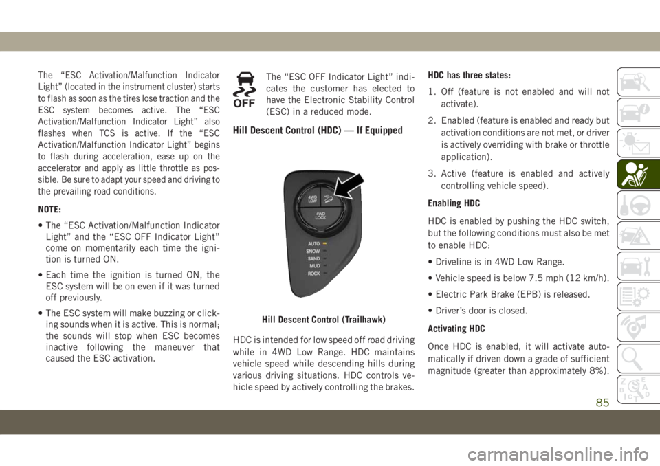
Hill Descent Control (HDC) — If Equipped
HDC is intended for low speed off road driving
while in 4WD Low Range. HDC maintains
vehicle speed while descending hills during
various driving situations. HDC controls ve-
hicle speed by actively controlling the brakes.HDC has three states:
1. Off (feature is not enabled and will not
activate).
2. Enabled (feature is enabled and ready but
activation conditions are not met, or driver
is actively overriding with brake or throttle
application).
3. Active (feature is enabled and actively
controlling vehicle speed).
Enabling HDC
HDC is enabled by pushing the HDC switch,
but the following conditions must also be met
to enable HDC:
• Driveline is in 4WD Low Range.
• Vehicle speed is below 7.5 mph (12 km/h).
• Electric Park Brake (EPB) is released.
• Driver’s door is closed.
Activating HDC
Once HDC is enabled, it will activate auto-
matically if driven down a grade of sufficient
magnitude (greater than approximately 8%).
Hill Descent Control (Trailhawk)
85
Page 162 of 362
SELEC-TERRAIN —
IF EQUIPPED
Selec-Terrain combines the capabilities of
the vehicle control systems, along with driver
input, to provide the best performance for all
terrains.
Mode Selection Guide
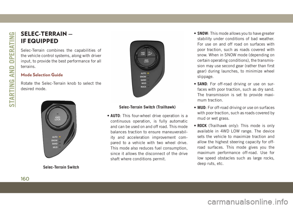
Rotate the Selec-Terrain knob to select the
desired mode.
•AUTO: This four-wheel drive operation is a
continuous operation, is fully automatic
and can be used on and off road. This mode
balances traction to ensure maneuverabil-
ity and acceleration improvement com-
pared to a vehicle with two wheel drive.
This mode also reduces fuel consumption,
since it allows the disconnect of the drive
shaft where conditions permit.•SNOW: This mode allows you to have greater
stability under conditions of bad weather.
For use on and off road on surfaces with
poor traction, such as roads covered with
snow. When in SNOW mode (depending on
certain operating conditions), the transmis-
sion may use second gear (rather than first
gear) during launches, to minimize wheel
slippage.
•SAND: For off-road driving or use on sur-
faces with poor traction, such as dry sand.
The transmission is set to provide maxi-
mum traction.
•MUD: For off-road driving or use on surfaces
with poor traction, such as roads covered by
mud or wet grass.
•ROCK(Trailhawk only): This mode is only
available in 4WD LOW range. The device
sets the vehicle to maximize traction and
allow the highest steering capacity for off-
road surfaces. This mode gives you the
maximum performance off-road. Use for
low speed obstacles such as large rocks,
deep ruts, etc.
Selec-Terrain Switch
Selec-Terrain Switch (Trailhawk)STARTING AND OPERATING
160
Page 181 of 362
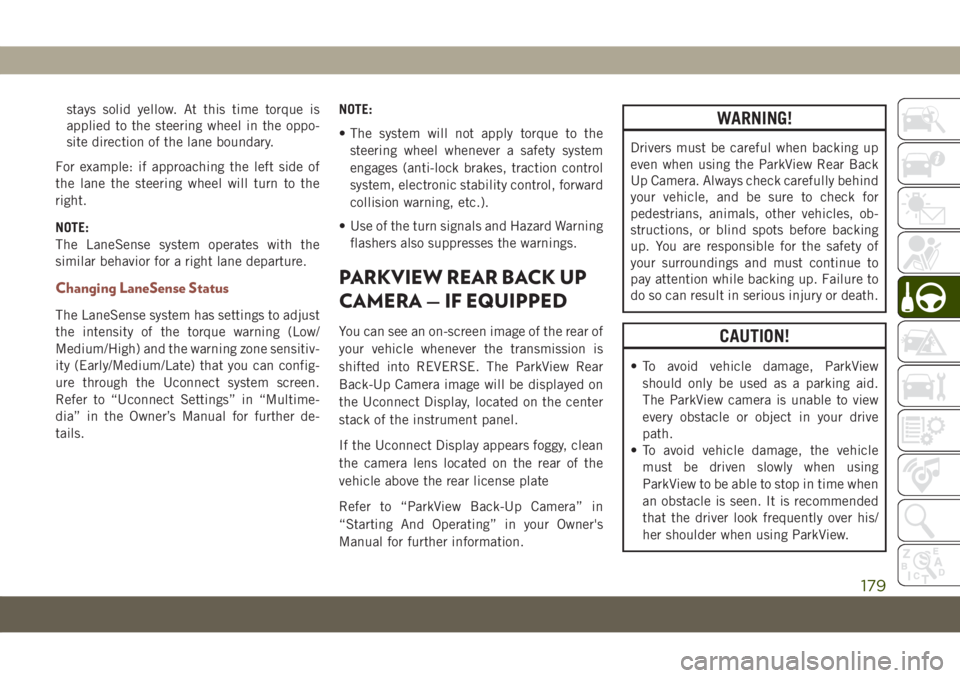
stays solid yellow. At this time torque is
applied to the steering wheel in the oppo-
site direction of the lane boundary.
For example: if approaching the left side of
the lane the steering wheel will turn to the
right.
NOTE:
The LaneSense system operates with the
similar behavior for a right lane departure.
Changing LaneSense Status
The LaneSense system has settings to adjust
the intensity of the torque warning (Low/
Medium/High) and the warning zone sensitiv-
ity (Early/Medium/Late) that you can config-
ure through the Uconnect system screen.
Refer to “Uconnect Settings” in “Multime-
dia” in the Owner’s Manual for further de-
tails.NOTE:
• The system will not apply torque to the
steering wheel whenever a safety system
engages (anti-lock brakes, traction control
system, electronic stability control, forward
collision warning, etc.).
• Use of the turn signals and Hazard Warning
flashers also suppresses the warnings.
PARKVIEW REAR BACK UP
CAMERA — IF EQUIPPED
You can see an on-screen image of the rear of
your vehicle whenever the transmission is
shifted into REVERSE. The ParkView Rear
Back-Up Camera image will be displayed on
the Uconnect Display, located on the center
stack of the instrument panel.
If the Uconnect Display appears foggy, clean
the camera lens located on the rear of the
vehicle above the rear license plate
Refer to “ParkView Back-Up Camera” in
“Starting And Operating” in your Owner's
Manual for further information.
WARNING!
Drivers must be careful when backing up
even when using the ParkView Rear Back
Up Camera. Always check carefully behind
your vehicle, and be sure to check for
pedestrians, animals, other vehicles, ob-
structions, or blind spots before backing
up. You are responsible for the safety of
your surroundings and must continue to
pay attention while backing up. Failure to
do so can result in serious injury or death.
CAUTION!
• To avoid vehicle damage, ParkView
should only be used as a parking aid.
The ParkView camera is unable to view
every obstacle or object in your drive
path.
• To avoid vehicle damage, the vehicle
must be driven slowly when using
ParkView to be able to stop in time when
an obstacle is seen. It is recommended
that the driver look frequently over his/
her shoulder when using ParkView.
179
Page 257 of 362
WARNING!
resulting in serious injury or death. Use
only the tire and wheel sizes with load
ratings approved for your vehicle.
• Never use a tire with a smaller load index
or capacity, other than what was origi-
nally equipped on your vehicle. Using a
tire with a smaller load index could re-
sult in tire overloading and failure. You
could lose control and have a collision.
• Failure to equip your vehicle with tires
having adequate speed capability can
result in sudden tire failure and loss of
vehicle control.
CAUTION!
Replacing original tires with tires of a
different size may result in false speedom-
eter and odometer readings.
Tire Types
All Season Tires — If Equipped
All Season tires provide traction for all sea-
sons (Spring, Summer, Fall, and Winter).
Traction levels may vary between different all
season tires. All season tires can be identified
by the M+S, M&S, M/S or MS designation on
the tire sidewall. Use all season tires only in
sets of four; failure to do so may adversely
affect the safety and handling of your vehicle.
Summer Or Three Season Tires —
If Equipped
Summer tires provide traction in both wet
and dry conditions, and are not intended to
be driven in snow or on ice. If your vehicle is
equipped with Summer tires, be aware these
tires are not designed for Winter or cold
driving conditions. Install Winter tires on your
vehicle when ambient temperatures are less
than 40°F (5°C) or if roads are covered with
ice or snow. For more information, contact an
authorized dealer.
Summer tires do not contain the all season
designation or mountain/snowflake symbol
on the tire sidewall. Use Summer tires only insets of four; failure to do so may adversely
affect the safety and handling of your vehicle.
WARNING!
Do not use Summer tires in snow/ice con-
ditions. You could lose vehicle control,
resulting in severe injury or death. Driving
too fast for conditions also creates the
possibility of loss of vehicle control.
Snow Tires
Some areas of the country require the use of
snow tires during the Winter. Snow tires can
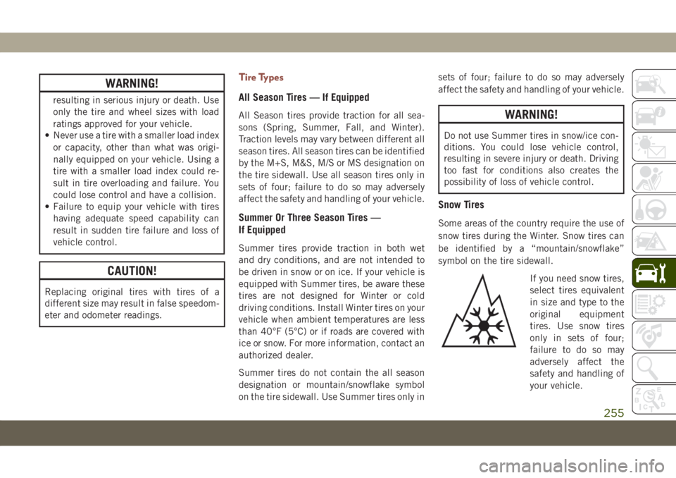
be identified by a “mountain/snowflake”
symbol on the tire sidewall.
If you need snow tires,
select tires equivalent
in size and type to the
original equipment
tires. Use snow tires
only in sets of four;
failure to do so may
adversely affect the
safety and handling of
your vehicle.
255
Page 259 of 362
WARNING!
Compact and collapsible spares are for
temporary emergency use only. With these
spares, do not drive more than 50 mph
(80 km/h). Temporary use spares have lim-
ited tread life. When the tread is worn to
the tread wear indicators, the temporary
use spare tire needs to be replaced. Be
sure to follow the warnings, which apply to
your spare. Failure to do so could result in
spare tire failure and loss of vehicle con-
trol.
Full Size Spare — If Equipped
The full size spare is for temporary emer-
gency use only. This tire may look like the
originally equipped tire on the front or rear
axle of your vehicle, but it is not. This spare
tire may have limited tread life. When the
tread is worn to the tread wear indicators, the
temporary use full size spare tire needs to be
replaced. Since it is not the same as your
original equipment tire, replace (or repair)
the original equipment tire and reinstall on
the vehicle at the first opportunity.
Limited Use Spare — If Equipped
The limited use spare tire is for temporary
emergency use only. This tire is identified by
a label located on the limited use spare
wheel. This label contains the driving limita-
tions for this spare. This tire may look like the
original equipped tire on the front or rear axle
of your vehicle, but it is not. Installation of
this limited use spare tire affects vehicle
handling. Since it is not the same as your
original equipment tire, replace (or repair)
the original equipment tire and reinstall on
the vehicle at the first opportunity.
WARNING!
Limited use spares are for emergency use
only. Installation of this limited use spare
tire affects vehicle handling. With this tire,
do not drive more than the speed listed on
the limited use spare wheel. Keep inflated
to the cold tire inflation pressures listed on
your Tire and Loading Information Placard
located on the driver’s side B-Pillar or the
rear edge of the driver’s side door. Replace
(or repair) the original equipment tire at
the first opportunity and reinstall it on your
WARNING!
vehicle. Failure to do so could result in loss
of vehicle control.
Tire Chains (Traction Devices)
Use of traction devices require sufficient tire-
to-body clearance. Follow these recommen-
dations to guard against damage:
• Traction device must be of proper size for
the tire, as recommended by the traction
device manufacturer.
• Install on front tires only.
• For a 215/65R16 tire, use of a snow trac-
tion device with a maximum projection of
7 mm beyond the tire profile is recom-
mended.
• No other tire sizes are recommended for
use with a tire chain or traction device.
NOTE:
Any aftermarket tire add on like tire chains
may effect the Tire Pressure Monitoring Sys-
tem (TPMS) feature performance.
257
Page 260 of 362
WARNING!
Using tires of different size and type
(M+S, Snow) between front and rear axles
can cause unpredictable handling. You
could lose control and have a collision.
CAUTION!
To avoid damage to your vehicle or tires,
observe the following precautions:
• Because of restricted traction device
clearance between tires and other sus-
pension components, it is important
that only traction devices in good condi-
tion are used. Broken devices can cause
serious damage. Stop the vehicle imme-
diately if noise occurs that could indi-
cate device breakage. Remove the dam-
aged parts of the device before further
use.
• Install device as tightly as possible and
then retighten after driving about ½ mile
(0.8 km).
• Do not exceed 30 mph (48 km/h).
CAUTION!
• Drive cautiously and avoid severe turns
and large bumps, especially with a
loaded vehicle.
• Do not drive for a prolonged period on
dry pavement.
• Observe the traction device manufactur-
er’s instructions on the method of instal-
lation, operating speed, and conditions
for use. Always use the suggested oper-
ating speed of the device manufacturer’s
if it is less than 30 mph (48 km/h).
• Do not use traction devices on a com-
pact spare tire.
Tire Rotation Recommendations
The tires on the front and rear of your vehicle
operate at different loads and perform differ-
ent steering, handling, and braking func-
tions. For these reasons, they wear at unequal
rates.
These effects can be reduced by timely rota-
tion of tires. The benefits of rotation are espe-
cially worthwhile with aggressive tread designs
such as those on On/Off Road type tires.Rotation will increase tread life, help to main-
tain mud, snow, and wet traction levels, and
contribute to a smooth, quiet ride.
Refer to the “Maintenance Plan” for the
proper maintenance intervals. The reasons
for any rapid or unusual wear should be
corrected prior to rotation being performed.
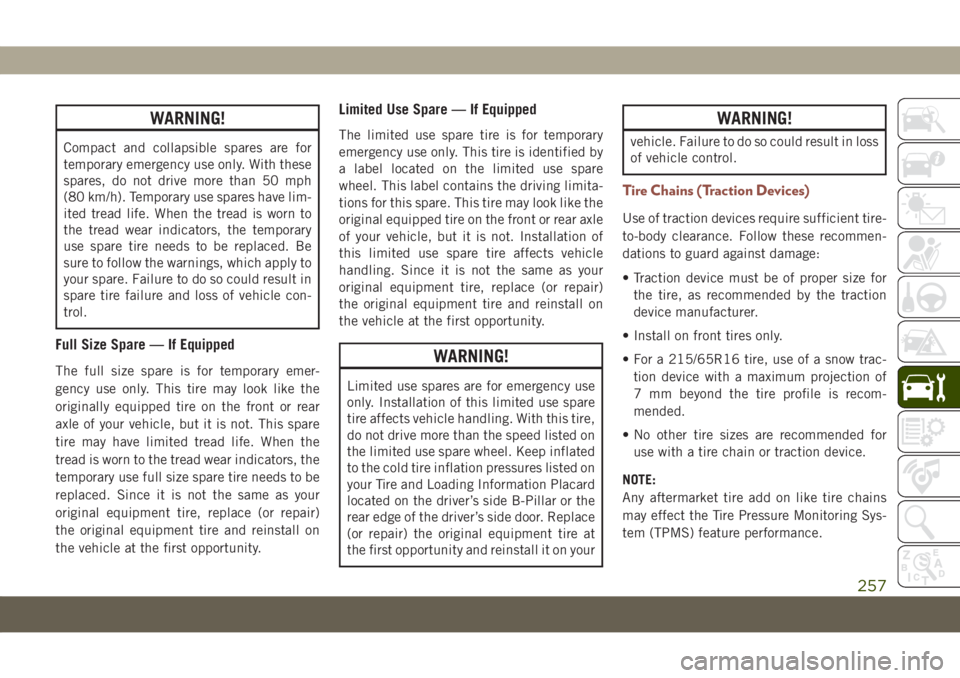
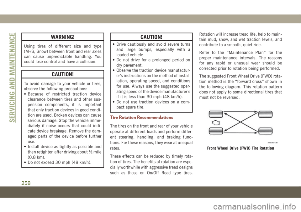
The suggested Front Wheel Drive (FWD) rota-
tion method is the “forward cross” shown in
the following diagram. This rotation pattern
does not apply to some directional tires that
must not be reversed.
Front Wheel Drive (FWD) Tire Rotation
SERVICING AND MAINTENANCE
258
Page 352 of 362
Bulbs, Light.................140
Camera, Rear................179
Capacities, Fluid..............274
Caps, Filler
Fuel....................180
Oil (Engine)...............240
Radiator (Coolant Pressure)......247
Carbon Monoxide Warning.....138, 272
Car Washes..................260
Chains, Tire..................257
Change Oil Indicator.............61
Changing A Flat Tire.........208, 250
Check Engine Light (Malfunction
Indicator Light)..............77
Checking Your Vehicle For Safety. . . .138
Checks, Safety................138
Child Safety Locks..............23
Cleaning
Windshield Wiper Blades.......245
Climate Control................39
Clock Settings................284
Compact Spare Tire.............256
Computer, Trip/Travel.............64
Cooling Pressure Cap (Radiator Cap) . .247
Cooling System...............247
Coolant Level..............247Cooling Capacity............274
Pressure Cap...............247
Radiator Cap...............247
Selection Of Coolant
(Antifreeze)............274, 276
Cruise Light.............74, 75, 76
Customer Assistance............332
Customer Programmable Features. . . .307
Cybersecurity.................282
Daytime Running Lights........33, 34
Dealer Service................245
Defroster, Windshield............139
Diagnostic System, Onboard........76
Diesel Fuel.................
.272
Diesel Fuel Requirements
.........272
Dimmer Switch
Headlight...............33, 34
Dipsticks
Oil (Engine)...............243
Disabled Vehicle Towing..........226
Do Not Disturb............320, 329
Door Ajar.................66, 67
Door Ajar Light..............66, 67
Drag And Drop Menu............289
Driver’s Seat Back Tilt............24Easy Entry Seats...............27
Electrical Outlet, Auxiliary
(Power Outlet)...............56
Electric Brake Control System.......80
Anti-Lock Brake System.........79
Traction Control System.........80
Electric Parking Brake...........145
Electronic Speed Control
(Cruise Control)..............163
Electronic Stability Control (ESC).....82
Electronic Throttle Control
Warning Light...............66
Emergency, In Case Of
Hazard Warning Flasher........193
Jacking...............208, 250
Jump Starting..............220
Tow Hooks................228
Towing...................226
Emission Control System
Maintenance................77
Emissions...................280
Engine.....................240
Checking Oil Level...........243
Coolant (Antifreeze)..........276
Cooling..................247
Exhaust Gas Caution.......138, 272
Jump Starting..............220
INDEX
350