JEEP COMPASS 2023 Owners Manual
Manufacturer: JEEP, Model Year: 2023, Model line: COMPASS, Model: JEEP COMPASS 2023Pages: 344, PDF Size: 18.8 MB
Page 291 of 344
SERVICING AND MAINTENANCE289
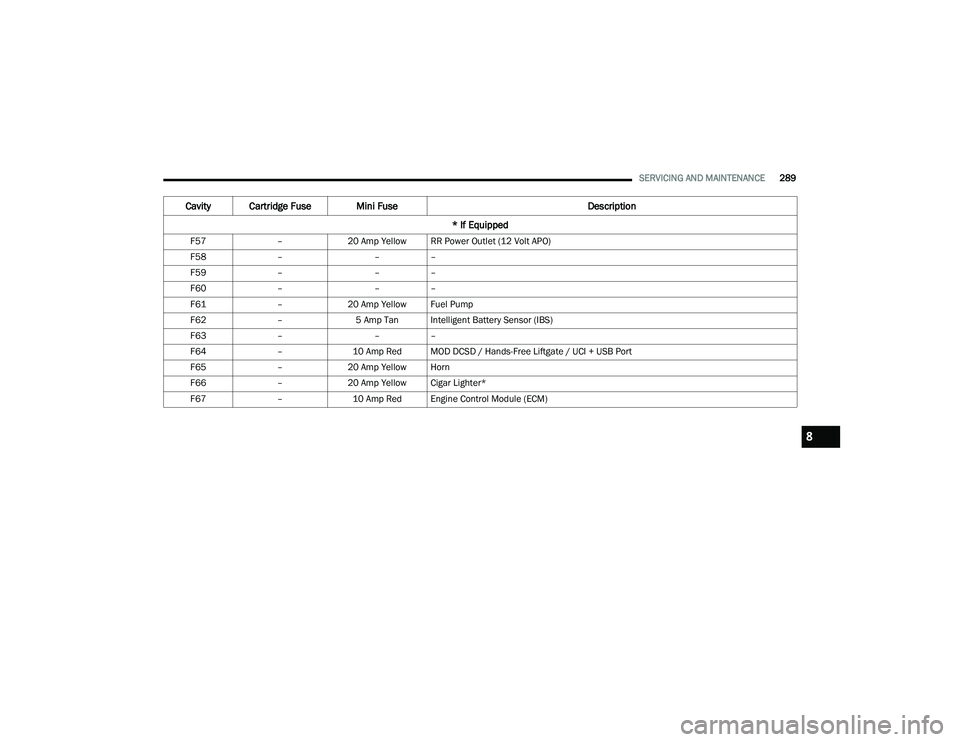
F57 –20 Amp Yellow RR Power Outlet (12 Volt APO)
F58 – ––
F59 – ––
F60 – ––
F61 –20 Amp Yellow Fuel Pump
F62 –5 Amp Tan Intelligent Battery Sensor (IBS)
F63 – ––
F64 –10 Amp Red MOD DCSD / Hands-Free Liftgate / UCI + USB Port
F65 –20 Amp Yellow Horn
F66 –20 Amp Yellow Cigar Lighter*
F67 –10 Amp Red Engine Control Module (ECM)
Cavity Cartridge Fuse Mini Fuse Description
* If Equipped
8
22_MP_OM_EN_USC_t.book Page 289
Page 292 of 344
290SERVICING AND MAINTENANCE
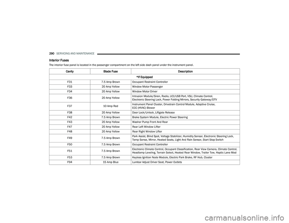
Interior Fuses
The interior fuse panel is located in the passenger compartment on the left side dash panel under the instrument panel.
CavityBlade Fuse Description
*If Equipped
F31 7.5 Amp Brown Occupant Restraint Controller
F33 20 Amp Yellow Window Motor Passenger
F34 20 Amp Yellow Window Motor Driver
F36 20 Amp YellowIntrusion Module/Siren, Radio, UCI/USB Port, VSU, Climate Control,
Electronic Steering Lock, Power Folding Mirrors, Security Gateway/DTV
F37 10 Amp RedInstrument Panel Cluster, Drivetrain Control Module, Adaptive Cruise,
ECC (HVAC) Blower
F38 20 Amp Yellow Door Lock/Unlock, Liftgate Release
F42 7.5 Amp Brown Brake System Module, Electric Power Steering
F43 20 Amp Yellow Washer Pump Front And Rear
F47 20 Amp Yellow Rear Left Window Lifter
F48 20 Amp Yellow Rear Right Window Lifter
F49 7.5 Amp BrownPark Assist, Blind Spot, Voltage Stabilizer, Humidity Sensor, Electronic Steering Lock,
Temp Sense, Mirror, Heated Seats, Light And Rain Sensor, Start Stop Switch
F50 7.5 Amp Brown Occupant Restraint Controller
F51 7.5 Amp BrownElectronic Climate Control, Occupant Classification, Rear View Camera, Climate Control,
Headlamp Leveling, Terrain Select, Heated Rear Window, Trailer Tow, Haptic Lane Mod
F53 7.5 Amp Brown Keyless Ignition Node Module, Electric Park Brake, RF Hub, Cluster
F94 15 Amp Blue Lumbar Adjust Driver Seat, Power Outlets
22_MP_OM_EN_USC_t.book Page 290
Page 293 of 344
SERVICING AND MAINTENANCE291
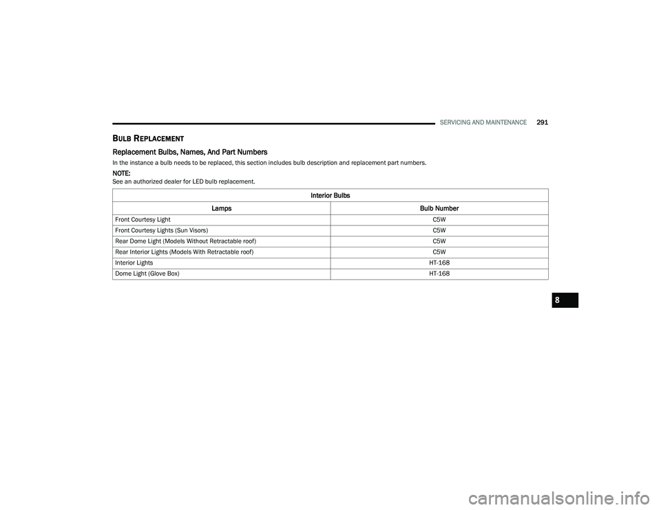
BULB REPLACEMENT
Replacement Bulbs, Names, And Part Numbers
In the instance a bulb needs to be replaced, this section includes bulb description and replacement part numbers.
NOTE:See an authorized dealer for LED bulb replacement.
Interior Bulbs
Lamps Bulb Number
Front Courtesy Light C5W
Front Courtesy Lights (Sun Visors) C5W
Rear Dome Light (Models Without Retractable roof) C5W
Rear Interior Lights (Models With Retractable roof) C5W
Interior Lights HT-168
Dome Light (Glove Box) HT-168
8
22_MP_OM_EN_USC_t.book Page 291
Page 294 of 344
292SERVICING AND MAINTENANCE
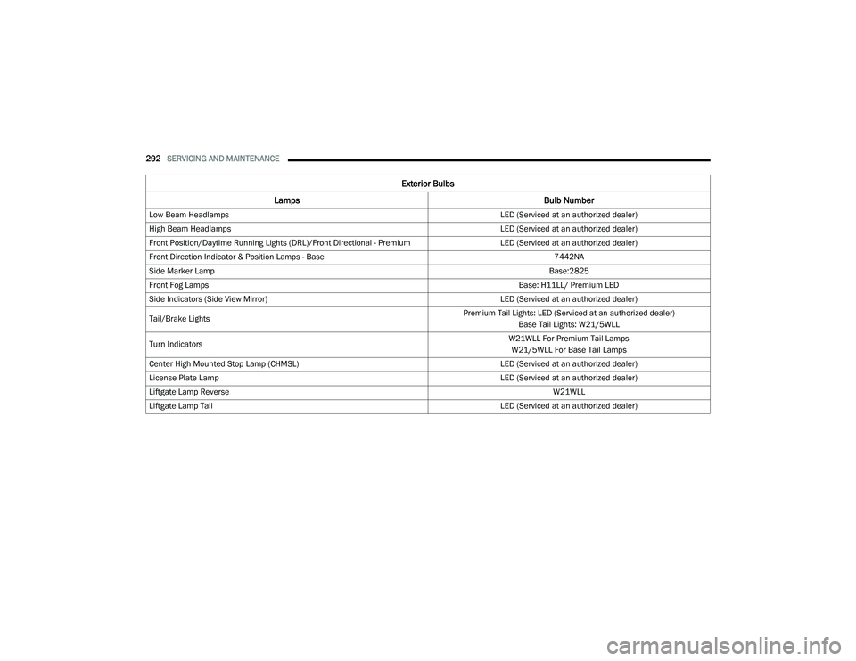
Exterior Bulbs
Lamps Bulb Number
Low Beam Headlamps LED (Serviced at an authorized dealer)
High Beam Headlamps LED (Serviced at an authorized dealer)
Front Position/Daytime Running Lights (DRL)/Front Directional - Premium LED (Serviced at an authorized dealer)
Front Direction Indicator & Position Lamps - Base 7442NA
Side Marker Lamp Base:2825
Front Fog Lamps Base: H11LL/ Premium LED
Side Indicators (Side View Mirror) LED (Serviced at an authorized dealer)
Tail/Brake Lights Premium Tail Lights: LED (Serviced at an authorized dealer)
Base Tail Lights: W21/5WLL
Turn Indicators W21WLL For Premium Tail Lamps
W21/5WLL For Base Tail Lamps
Center High Mounted Stop Lamp (CHMSL) LED (Serviced at an authorized dealer)
License Plate Lamp LED (Serviced at an authorized dealer)
Liftgate Lamp Reverse W21WLL
Liftgate Lamp Tail LED (Serviced at an authorized dealer)
22_MP_OM_EN_USC_t.book Page 292
Page 295 of 344
SERVICING AND MAINTENANCE293
Replacing Exterior Bulbs
Turn Signal Light/Position Lights (Base)
To replace the bulbs proceed as follows:
1. Open hood.
2. Reach behind headlamp near the radiator.
3. Remove the electrical connectors.
4. For the turn signal bulb, rotate in a counter -
clockwise direction and remove the bulb and
bulb socket. Pull the bulb axially to remove it
from the socket.
5. Install the bulb and sockets and rotate them clockwise making sure that it is properly
locked.
6. Reconnect the electrical connectors.
7. Close hood.
NOTE:It is advised referring to an authorized dealer. Front Fog Lights (Base)
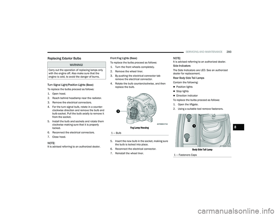
To replace the bulbs proceed as follows:
1. Turn the front wheels completely.
2. Remove the wheel liner.
3. By pushing the electrical connector tab
remove the electrical connector.
4. Rotate the bulb counterclockwise, and then replace the bulb.
Fog Lamp Housing
5. Insert the new bulb in the socket, making sure the bulb is locked into place.
6. Reconnect the electrical connector.
7. Reinstall the wheel liner.
NOTE:It is advised referring to an authorized dealer.
Side Indicators
The Side Indicators are LED. See an authorized
dealer for replacement.
Rear Body Side Tail Lamps
Contain the following:
Position lights
Stop lights
Direction indicator
To replace the bulbs proceed as follows:
1. Open the liftgate.
2. Using a suitable tool remove fasteners.
Body Side Tail Lamp
WARNING!
Carry out the operation of replacing lamps only
with the engine off. Also make sure that the
engine is cold, to avoid the danger of burns.
1 — Bulb
1 — Fasteners Caps
8
22_MP_OM_EN_USC_t.book Page 293
Page 296 of 344
294SERVICING AND MAINTENANCE
3. Disconnect the electrical connector by pushing the release.
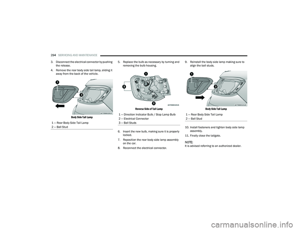
4. Remove the rear body side tail lamp, sliding it away from the back of the vehicle.
Body Side Tail Lamp
5. Replace the bulb as necessary by turning and
removing the bulb housing.
Reverse Side of Tail Lamp
6. Insert the new bulb, making sure it is properly locked.
7. Reposition the rear body side lamp assembly on the car.
8. Reconnect the electrical connector. 9. Reinstall the body side lamp making sure to
align the ball studs.
Body Side Tail Lamp
10. Install fasteners and tighten body side lamp assembly.
11. Finally close the tailgate.
NOTE:It is advised referring to an authorized dealer.
1 — Rear Body Side Tail Lamp
2 — Ball Stud
1 — Direction Indicator Bulb / Stop Lamp Bulb
2 — Electrical Connector
3 — Ball Studs1 — Rear Body Side Tail Lamp
2 — Ball Stud
22_MP_OM_EN_USC_t.book Page 294
Page 297 of 344
SERVICING AND MAINTENANCE295
Reverse Lamps
1. Open the liftgate.
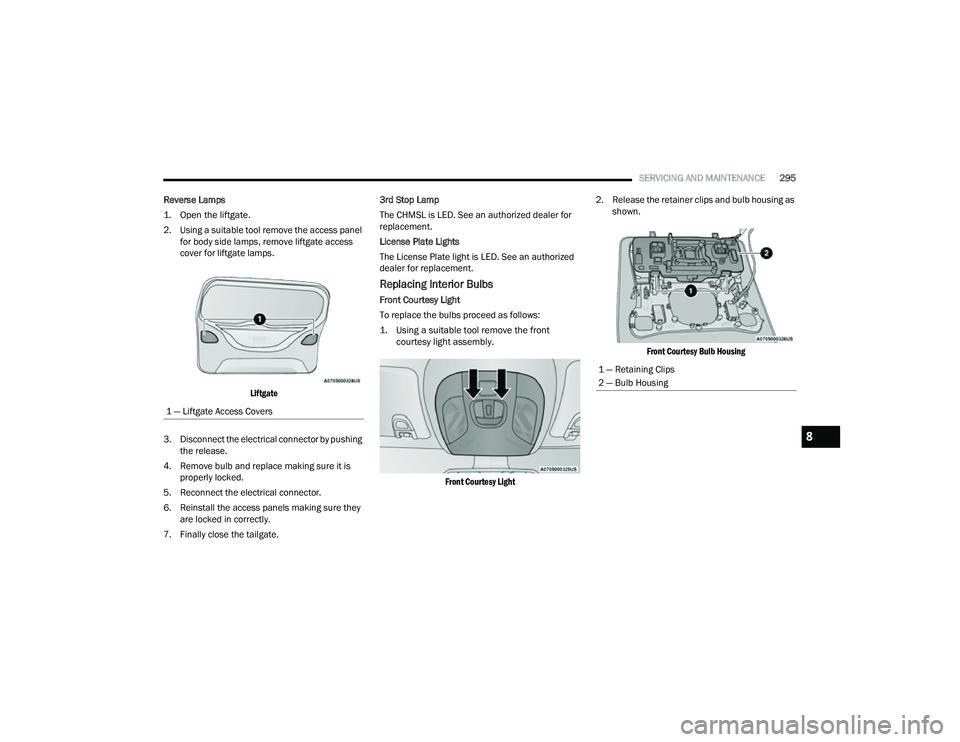
2. Using a suitable tool remove the access panel for body side lamps, remove liftgate access
cover for liftgate lamps.
Liftgate
3. Disconnect the electrical connector by pushing the release.
4. Remove bulb and replace making sure it is properly locked.
5. Reconnect the electrical connector.
6. Reinstall the access panels making sure they are locked in correctly.
7. Finally close the tailgate. 3rd Stop Lamp
The CHMSL is LED. See an authorized dealer for
replacement.
License Plate Lights
The License Plate light is LED. See an authorized
dealer for replacement.
Replacing Interior Bulbs
Front Courtesy Light
To replace the bulbs proceed as follows:
1. Using a suitable tool remove the front
courtesy light assembly.
Front Courtesy Light
2. Release the retainer clips and bulb housing as
shown.
Front Courtesy Bulb Housing
1 — Liftgate Access Covers
1 — Retaining Clips
2 — Bulb Housing
8
22_MP_OM_EN_USC_t.book Page 295
Page 298 of 344
296SERVICING AND MAINTENANCE
3. Replace the bulbs by pulling straight out of bulb housing.
Front Courtesy Bulb Housing
4. Insert the new bulbs, making sure that they are properly locked.
5. Reassemble the bulb housing and courtesy light housing making sure that they are
properly locked.
6. Install the front courtesy light, making sure that it is properly locked. Dome Light Vanity Mirror — If Equipped
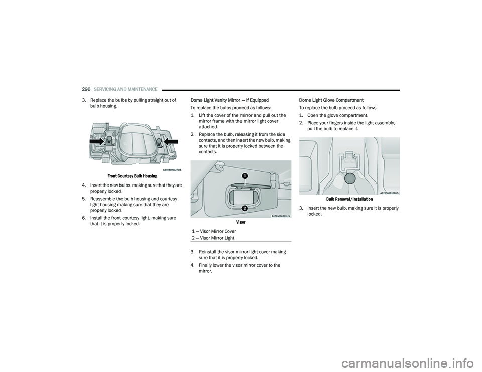
To replace the bulbs proceed as follows:
1. Lift the cover of the mirror and pull out the
mirror frame with the mirror light cover
attached.
2. Replace the bulb, releasing it from the side contacts, and then insert the new bulb, making
sure that it is properly locked between the
contacts.
Visor
3. Reinstall the visor mirror light cover making sure that it is properly locked.
4. Finally lower the visor mirror cover to the mirror. Dome Light Glove Compartment
To replace the bulb proceed as follows:
1. Open the glove compartment.
2. Place your fingers inside the light assembly,
pull the bulb to replace it.
Bulb Removal/Installation
3. Insert the new bulb, making sure it is properly locked.
1 — Visor Mirror Cover
2 — Visor Mirror Light
22_MP_OM_EN_USC_t.book Page 296
Page 299 of 344
SERVICING AND MAINTENANCE297
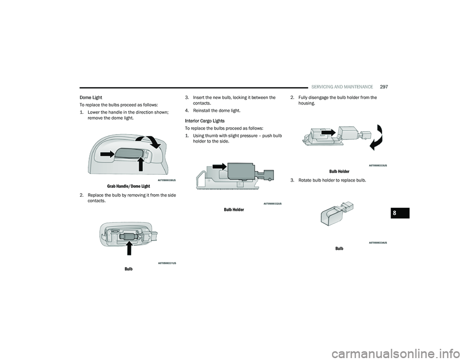
Dome Light
To replace the bulbs proceed as follows:
1. Lower the handle in the direction shown; remove the dome light.
Grab Handle/Dome Light
2. Replace the bulb by removing it from the side contacts.
Bulb
3. Insert the new bulb, locking it between the
contacts.
4. Reinstall the dome light.
Interior Cargo Lights
To replace the bulbs proceed as follows:
1. Using thumb with slight pressure – push bulb holder to the side.
Bulb Holder
2. Fully disengage the bulb holder from the
housing.
Bulb Holder
3. Rotate bulb holder to replace bulb.
Bulb
8
22_MP_OM_EN_USC_t.book Page 297
Page 300 of 344
298SERVICING AND MAINTENANCE
NOTE:It is recommended to have your bulbs replaced by
an authorized dealer.
TIRES
TIRE SAFETY INFORMATION
Tire safety information will cover aspects of the
following information: Tire Markings, Tire
Identification Numbers, Tire Terminology and
Definitions, Tire Pressures, and Tire Loading.
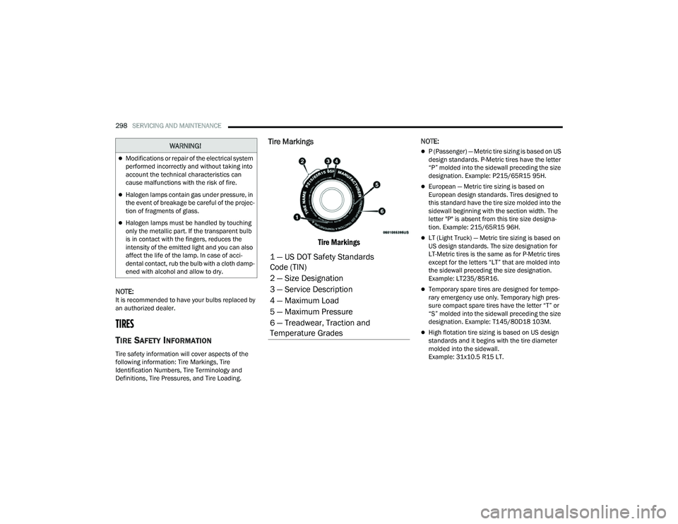
Tire Markings
Tire Markings
NOTE:
P (Passenger) — Metric tire sizing is based on US
design standards. P-Metric tires have the letter
“P” molded into the sidewall preceding the size
designation. Example: P215/65R15 95H.
European — Metric tire sizing is based on
European design standards. Tires designed to
this standard have the tire size molded into the
sidewall beginning with the section width. The
letter "P" is absent from this tire size designa -
tion. Example: 215/65R15 96H.
LT (Light Truck) — Metric tire sizing is based on
US design standards. The size designation for
LT-Metric tires is the same as for P-Metric tires
except for the letters “LT” that are molded into
the sidewall preceding the size designation.
Example: LT235/85R16.
Temporary spare tires are designed for tempo -
rary emergency use only. Temporary high pres -
sure compact spare tires have the letter “T” or
“S” molded into the sidewall preceding the size
designation. Example: T145/80D18 103M.
High flotation tire sizing is based on US design
standards and it begins with the tire diameter
molded into the sidewall.
Example: 31x10.5 R15 LT.
WARNING!
Modifications or repair of the electrical system
performed incorrectly and without taking into
account the technical characteristics can
cause malfunctions with the risk of fire.
Halogen lamps contain gas under pressure, in
the event of breakage be careful of the projec -
tion of fragments of glass.
Halogen lamps must be handled by touching
only the metallic part. If the transparent bulb
is in contact with the fingers, reduces the
intensity of the emitted light and you can also
affect the life of the lamp. In case of acci -
dental contact, rub the bulb with a cloth damp -
ened with alcohol and allow to dry.
1 — US DOT Safety Standards
Code (TIN)
2 — Size Designation
3 — Service Description
4 — Maximum Load
5 — Maximum Pressure
6 — Treadwear, Traction and
Temperature Grades
22_MP_OM_EN_USC_t.book Page 298