engine JEEP COMPASS 2023 Workshop Manual
[x] Cancel search | Manufacturer: JEEP, Model Year: 2023, Model line: COMPASS, Model: JEEP COMPASS 2023Pages: 344, PDF Size: 18.8 MB
Page 117 of 344
STARTING AND OPERATING115
POSSIBLE REASONS THE ENGINE DOES
N
OT AUTOSTOP
Prior to engine shut down, the system will check
many safety and comfort conditions to see if they
are fulfilled. Detailed information about the
operation of the Stop/Start system may be viewed
in the instrument cluster display Stop/Start
Screen. In the following situations the engine will
not stop:
Driver’s seat belt is not buckled.
Driver’s door is not closed.
Battery temperature is too warm or cold.
Battery charge is low.
The vehicle is on a steep grade.
Cabin heating or cooling is in process and an
acceptable cabin temperature has not been
achieved.
HVAC is set to full defrost mode at a high blower
speed.
HVAC is set to MAX A/C.
Engine has not reached normal operating
temperature.
The transmission is not in a forward gear.
Hood is open.
Vehicle is in 4WD LOW transfer case mode.
Brake pedal is not pressed with sufficient pres -
sure.
Accelerator pedal input.
Engine temperature is too high.
5 mph (8 km/h) threshold has not been
achieved from previous Autostop.
Steering angle beyond threshold.
Adaptive Cruise Control is on and speed is set.
It may be possible for the vehicle to be driven
several times without the Stop/Start system going
into a STOP/START READY state under more
extreme conditions of the items listed above.
TO START THE ENGINE WHILE IN
A
UTOSTOP MODE
While in a forward gear, the engine will start when
the brake pedal is released or the throttle pedal is
pressed. The transmission will automatically
re-engage upon engine restart. Conditions That Will Cause The Engine To Start
Automatically While In Autostop Mode:
The transmission selector is moved out of
DRIVE (D).
To maintain cabin temperature comfort.
HVAC is set to full defrost mode.
HVAC system temperature or fan speed is
manually adjusted.
Battery voltage drops too low.
Stop/Start OFF switch is pressed.
A Stop/Start system error occurs.
Vehicle is in 4WD LOW transfer case mode.
Conditions That Force An Application Of The
Electric Park Brake While In Autostop Mode:
The driver’s door is open and brake pedal
released.
The driver’s door is open and the driver’s seat
belt is unbuckled.
The engine hood has been opened.
A Stop/Start system error occurs.
If the Electric Park Brake (EPB) is applied with the
engine off, the engine may require a manual
restart and the EPB may require a manual release
(press brake pedal and press EPB switch)
Ú page 77.
4
22_MP_OM_EN_USC_t.book Page 115
Page 118 of 344
116STARTING AND OPERATING
TO MANUALLY TURN OFF THE STOP/
S
TART SYSTEM
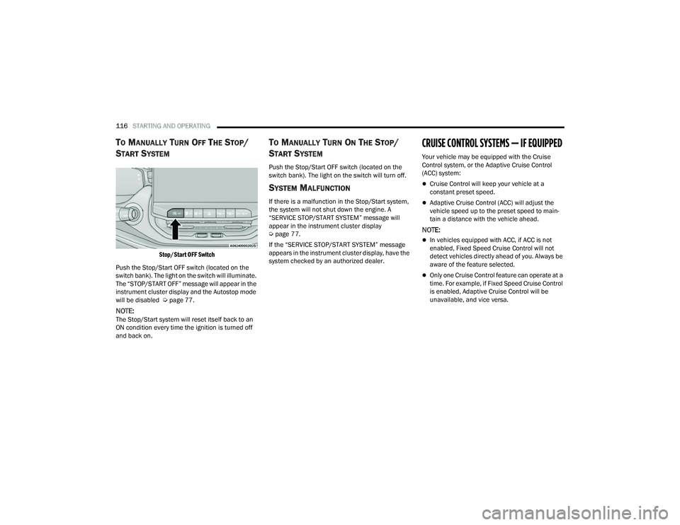
Stop/Start OFF Switch
Push the Stop/Start OFF switch (located on the
switch bank). The light on the switch will illuminate.
The “STOP/START OFF” message will appear in the
instrument cluster display and the Autostop mode
will be disabled Ú page 77.
NOTE:The Stop/Start system will reset itself back to an
ON condition every time the ignition is turned off
and back on.
TO MANUALLY TURN ON THE STOP/
S
TART SYSTEM
Push the Stop/Start OFF switch (located on the
switch bank). The light on the switch will turn off.
SYSTEM MALFUNCTION
If there is a malfunction in the Stop/Start system,
the system will not shut down the engine. A
“SERVICE STOP/START SYSTEM” message will
appear in the instrument cluster display
Ú page 77.
If the “SERVICE STOP/START SYSTEM” message
appears in the instrument cluster display, have the
system checked by an authorized dealer.
CRUISE CONTROL SYSTEMS — IF EQUIPPED
Your vehicle may be equipped with the Cruise
Control system, or the Adaptive Cruise Control
(ACC) system:
Cruise Control will keep your vehicle at a
constant preset speed.
Adaptive Cruise Control (ACC) will adjust the
vehicle speed up to the preset speed to main -
tain a distance with the vehicle ahead.
NOTE:
In vehicles equipped with ACC, if ACC is not
enabled, Fixed Speed Cruise Control will not
detect vehicles directly ahead of you. Always be
aware of the feature selected.
Only one Cruise Control feature can operate at a
time. For example, if Fixed Speed Cruise Control
is enabled, Adaptive Cruise Control will be
unavailable, and vice versa.
22_MP_OM_EN_USC_t.book Page 116
Page 120 of 344
118STARTING AND OPERATING
Metric Speed (km/h)
Pushing the SET (+) , or SET (-) button once will
result in a 1 km/h speed adjustment. Each
subsequent tap of the button results in an
adjustment of 1 km/h.
If the button is continually pushed, the set
speed will continue to adjust until the button is
released, then the new set speed will be estab -
lished.
To Accelerate For Passing
While the Cruise Control is set, press the
accelerator to pass as you would normally. When
the pedal is released, the vehicle will return to the
set speed.
USING CRUISE CONTROL ON HILLS
The transmission may downshift on hills to
maintain the vehicle set speed.
The Cruise Control system maintains speed up and
down hills. A slight speed change on moderate hills
is normal. On steep hills, a greater speed loss or
gain may occur so it may be preferable to drive
without Cruise Control.
To Resume Speed
To resume a previously set speed, push the RES
button and release. Resume can be used at any
speed above 20 mph (32 km/h).
To Deactivate
A tap on the brake pedal, or pushing the CANC
button, or normal brake pressure will deactivate
the Cruise Control system without erasing the set
speed from memory.
The following conditions will also deactivate the
Cruise Control without erasing the set speed from
memory:
Vehicle parking brake is applied
Stability event occurs
Gear selector is moved out of DRIVE
Engine overspeed occurs
Pushing the on/off button or placing the ignition in
the OFF position, will erase the set speed from
memory.
ADAPTIVE CRUISE CONTROL (ACC)
Adaptive Cruise Control (ACC) increases the driving
convenience provided by Cruise Control while
traveling on highways and major roadways.
However, it is not a safety system and not designed
to prevent collisions. The Cruise Control function
performs differently if your vehicle is not equipped
with ACC Ú page 117.
ACC will allow you to keep Cruise Control engaged
in light to moderate traffic conditions without the
constant need to reset your speed. ACC utilizes a
radar sensor and a forward facing camera
designed to detect a vehicle directly ahead of you
to maintain a set speed.
NOTE:
If the ACC sensor detects a vehicle ahead, ACC
will apply limited braking or accelerate (not to
exceed the original set speed) automatically to
maintain a preset following distance, while
matching the speed of the vehicle ahead.
Any chassis/suspension or tire size modifica -
tions to the vehicle will affect the performance
of the Adaptive Cruise Control and Forward Colli -
sion Warning system.
Fixed Speed Cruise Control (ACC not enabled)
will not detect vehicles directly ahead of you.
Always be aware of the feature selected
Ú page 328.
WARNING!
Cruise Control can be dangerous where the
system cannot maintain a constant speed. Your
vehicle could go too fast for the conditions, and
you could lose control and have an accident. Do
not use Cruise Control in heavy traffic or on roads
that are winding, icy, snow-covered or slippery.
22_MP_OM_EN_USC_t.book Page 118
Page 124 of 344
122STARTING AND OPERATING
To Resume
If there is a set speed in memory, push the RES
(resume) button and remove your foot from the
accelerator pedal. The instrument cluster display
will show the last set speed.
Resume can be used at any speed above 20 mph
(32 km/h) when only Fixed Speed Cruise Control is
being used.
Resume can be used at any speed above 0 mph
(0 km/h) when ACC is active.
NOTE:
If your vehicle is at standstill longer than two
seconds, the driver will either have to push the
RES (resume) button, or apply the accelerator
pedal to reengage the Adaptive Cruise Control
(ACC) to the existing set speed
ACC cannot be resumed if there is a stationary
vehicle in front of your vehicle in close proximity.
To Vary The Speed Setting
To Increase Or Decrease The Set Speed
After setting a speed, you can increase the set
speed by pushing the SET (+) button, or decrease
speed by pushing the SET (-) button.
U.S. Speed (mph)
Pushing the SET (+) , or SET (-) button once will
result in a 1 mph speed adjustment. Each
subsequent tap of the button results in an
adjustment of 1 mph.
If the button is continually pushed, the set
speed will continue to adjust in 5 mph incre -
ments until the button is released. The new set
speed is reflected in the instrument cluster
display.
Metric Speed (km/h)
Pushing the SET (+) , or SET (-) button once will
result in a 1 km/h speed adjustment. Each
subsequent tap of the button results in an
adjustment of 1 km/h.
If the button is continually pushed, the set
speed will continue to adjust in 10 km/h incre -
ments until the button is released. The new set
speed is reflected in the instrument cluster
display.
NOTE:When you override and push the SET (+) button or
SET (-) button, the new set speed will be the current
speed of the vehicle.
When ACC Is Active
When you use the SET (-) button to decelerate, if
the engine’s braking power does not slow the
vehicle sufficiently to reach the set speed, the
brake system will automatically slow the
vehicle.
The ACC system decelerates the vehicle to a full
stop when following the vehicle in front. If your
vehicle follows the vehicle in front to a standstill,
after two seconds the driver will either have to
push the RES (resume) button, or apply the
accelerator pedal to reengage the ACC to the
existing set speed.
The ACC system maintains set speed when
driving uphill and downhill. However, a slight
speed change on moderate hills is normal. In
addition, downshifting may occur while climbing
uphill or descending downhill. This is normal
operation and necessary to maintain set speed.
When driving uphill and downhill, the ACC
system will cancel if the braking temperature
exceeds normal range (overheated).
WARNING!
The Resume function should only be used if
traffic and road conditions permit. Resuming a
set speed that is too high or too low for
prevailing traffic and road conditions could
cause the vehicle to accelerate or decelerate too
sharply for safe operation. Failure to follow these
warnings can result in a collision and death or
serious personal injury.
22_MP_OM_EN_USC_t.book Page 122
Page 155 of 344
STARTING AND OPERATING153
4. Keep the nozzle in the filler for five seconds after nozzle clicks to allow fuel to drain from
the nozzle.
5. Remove the fuel nozzle and close the fuel door.
VEHICLE LOADING
CERTIFICATION LABEL
As required by National Highway Traffic Safety
Administration regulations, your vehicle has a
certification label affixed to the driver's side door or
pillar. This label contains the month and year of
manufacture, Gross Vehicle Weight Rating
(GVWR), front and rear Gross Axle Weight Rating
(GAWR), and Vehicle Identification Number (VIN).
A Month-Day-Hour (MDH) number is included on
this label and indicates the Month, Day and Hour of
manufacture. The bar code that appears on the
bottom of the label is your VIN.
Gross Vehicle Weight Rating (GVWR)
The GVWR is the total permissible weight of your
vehicle including driver, passengers, vehicle,
options and cargo. The label also specifies
maximum capacities of front and rear Gross Axle
Weight Rating (GAWR). Total load must be limited so
GVWR and front and rear GAWR are not exceeded.
Payload
The payload of a vehicle is defined as the allowable
load weight a truck can carry, including the weight
of the driver, all passengers, options and cargo.
Gross Axle Weight Rating (GAWR)
The GAWR is the maximum permissible load on the
front and rear axles. The load must be distributed
in the cargo area so that the GAWR of each axle is
not exceeded.
Each axle GAWR is determined by the components
in the system with the lowest load carrying capacity
(axle, springs, tires or wheels). Heavier axles or suspension components sometimes specified by
purchasers for increased durability does not
necessarily increase the vehicle's GVWR.
Tire Size
The tire size on the Vehicle Certification Label
represents the actual tire size on your vehicle.
Replacement tires must be equal to the load
capacity of this tire size.
Rim Size
This is the rim size that is appropriate for the tire
size listed.
Inflation Pressure
This is the cold tire inflation pressure for your
vehicle for all loading conditions up to full GAWR.
Curb Weight
The curb weight of a vehicle is defined as the total
weight of the vehicle with all fluids, including
vehicle fuel, at full capacity conditions, and with no
occupants or cargo loaded into the vehicle. The
front and rear curb weight values are determined
by weighing your vehicle on a commercial scale
before any occupants or cargo are added.
Loading
The actual total weight and the weight of the front
and rear of your vehicle at the ground can best be
determined by weighing it when it is loaded and
ready for operation.
WARNING!
Never have any smoking materials lit in or
near the vehicle when the fuel door is open or
the tank is being filled.
Never add fuel when the engine is running.
This is in violation of most state and federal
fire regulations and may cause the Malfunc
-
tion Indicator Light to turn on.
A fire may result if fuel is pumped into a
portable container that is inside of a vehicle.
You could be burned. Always place fuel
containers on the ground while filling.
4
22_MP_OM_EN_USC_t.book Page 153
Page 157 of 344
STARTING AND OPERATING155
Trailer Sway Control (TSC)
The TSC can be a mechanical telescoping link that
can be installed between the hitch receiver and the
trailer tongue that typically provides adjustable
friction associated with the telescoping motion to
dampen any unwanted trailer swaying motions
while traveling.
If equipped, the electronic TSC recognizes a
swaying trailer and automatically applies individual
wheel brakes and/or reduces engine power to
attempt to eliminate the trailer sway.
Weight-Carrying Hitch
A weight-carrying hitch supports the trailer tongue
weight, just as if it were luggage located at a hitch
ball or some other connecting point of the vehicle. These kinds of hitches are commonly used to tow
small and medium sized trailers.
Weight-Distributing Hitch
A Weight-Distributing system works by applying
leverage through spring (load) bars. They are
typically used for heavier loads to distribute trailer
tongue weight to the tow vehicle's front axle and
the trailer axle(s). When used in accordance with
the manufacturer's directions, it provides for a
more level ride, offering more consistent steering
and brake control thereby enhancing towing
safety. The addition of a friction/hydraulic sway
control also dampens sway caused by traffic and
crosswinds and contributes positively to tow
vehicle and trailer stability. Trailer sway control and
a Weight-Distributing (load equalizing) Hitch are recommended for heavier Tongue Weights (TW)
and may be required depending on vehicle and
trailer configuration/loading to comply with Gross
Axle Weight Rating (GAWR) requirements.
TRAILER TOWING WEIGHTS (MAXIMUM TRAILER WEIGHT RATINGS)
WARNING!
An improperly adjusted Weight-Distributing
Hitch system may reduce handling, stability,
braking performance, and could result in a
collision.
Weight-Distributing systems may not be
compatible with surge brake couplers. Consult
with your hitch and trailer manufacturer or a
reputable Recreational Vehicle dealer for
additional information.
Engine/Transmission
ModelMaximum GTW Maximum Trailer TW
2.4L / 6 Speed Auto FWDTrailer towing is not recommended.
2.4L / 9 Speed Auto FWD or 4WD2,000 lb (907 kg) 200 lb (90 kg)
When towing a trailer, the technically permissible laden weight may be exceeded by not more than 10% or 220 lb (100 kg), whichever is lower provided that the operating speed is restricted to 62 mph (100 km/h) or less.
Refer to local laws for maximum trailer towing speeds and loads.
Towing limits quoted represent the maximum towing ability of the vehicle at its Gross Combined Mass to restart on a 12 percent gradient at sea level. The performance and economy of all models will be reduced when used for towing.
4
22_MP_OM_EN_USC_t.book Page 155
Page 158 of 344
156STARTING AND OPERATING
(Continued)
TRAILER AND TONGUE WEIGHT
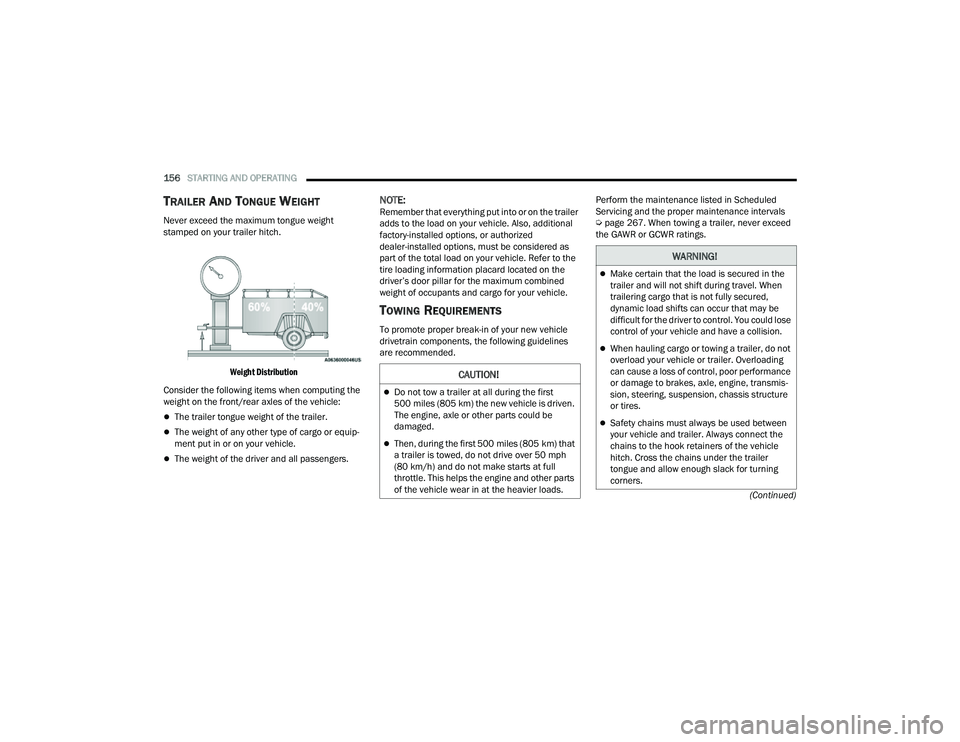
Never exceed the maximum tongue weight
stamped on your trailer hitch.
Weight Distribution
Consider the following items when computing the
weight on the front/rear axles of the vehicle:
The trailer tongue weight of the trailer.
The weight of any other type of cargo or equip -
ment put in or on your vehicle.
The weight of the driver and all passengers.
NOTE:Remember that everything put into or on the trailer
adds to the load on your vehicle. Also, additional
factory-installed options, or authorized
dealer-installed options, must be considered as
part of the total load on your vehicle. Refer to the
tire loading information placard located on the
driver’s door pillar for the maximum combined
weight of occupants and cargo for your vehicle.
TOWING REQUIREMENTS
To promote proper break-in of your new vehicle
drivetrain components, the following guidelines
are recommended. Perform the maintenance listed in Scheduled
Servicing and the proper maintenance intervals
Ú
page 267. When towing a trailer, never exceed
the GAWR or GCWR ratings.
CAUTION!
Do not tow a trailer at all during the first
500 miles (805 km) the new vehicle is driven.
The engine, axle or other parts could be
damaged.
Then, during the first 500 miles (805 km) that
a trailer is towed, do not drive over 50 mph
(80 km/h) and do not make starts at full
throttle. This helps the engine and other parts
of the vehicle wear in at the heavier loads.
WARNING!
Make certain that the load is secured in the
trailer and will not shift during travel. When
trailering cargo that is not fully secured,
dynamic load shifts can occur that may be
difficult for the driver to control. You could lose
control of your vehicle and have a collision.
When hauling cargo or towing a trailer, do not
overload your vehicle or trailer. Overloading
can cause a loss of control, poor performance
or damage to brakes, axle, engine, transmis -
sion, steering, suspension, chassis structure
or tires.
Safety chains must always be used between
your vehicle and trailer. Always connect the
chains to the hook retainers of the vehicle
hitch. Cross the chains under the trailer
tongue and allow enough slack for turning
corners.
22_MP_OM_EN_USC_t.book Page 156
Page 161 of 344
STARTING AND OPERATING159
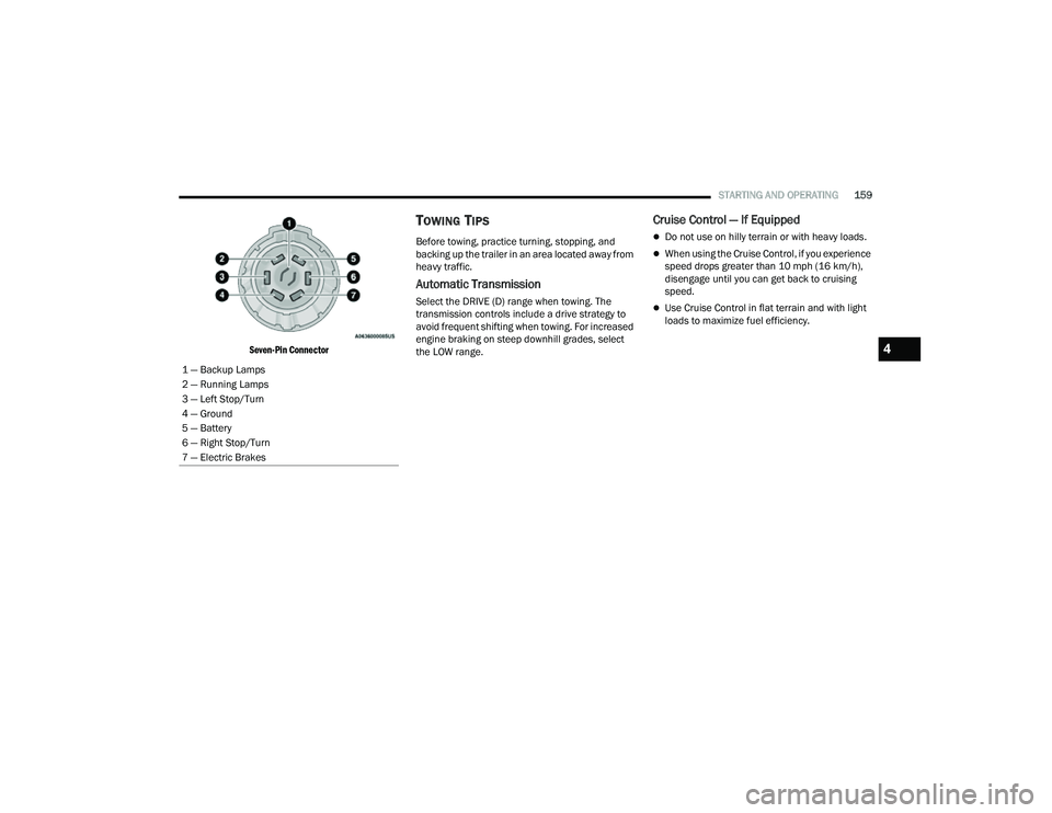
Seven-Pin Connector
TOWING TIPS
Before towing, practice turning, stopping, and
backing up the trailer in an area located away from
heavy traffic.
Automatic Transmission
Select the DRIVE (D) range when towing. The
transmission controls include a drive strategy to
avoid frequent shifting when towing. For increased
engine braking on steep downhill grades, select
the LOW range.
Cruise Control — If Equipped
Do not use on hilly terrain or with heavy loads.
When using the Cruise Control, if you experience
speed drops greater than 10 mph (16 km/h),
disengage until you can get back to cruising
speed.
Use Cruise Control in flat terrain and with light
loads to maximize fuel efficiency.
1 — Backup Lamps
2 — Running Lamps
3 — Left Stop/Turn
4 — Ground
5 — Battery
6 — Right Stop/Turn
7 — Electric Brakes
4
22_MP_OM_EN_USC_t.book Page 159
Page 162 of 344
160STARTING AND OPERATING
RECREATIONAL TOWING (BEHIND MOTORHOME)
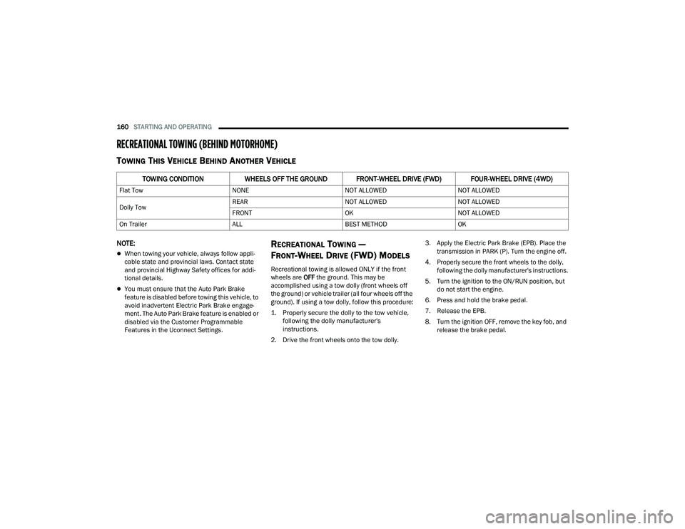
TOWING THIS VEHICLE BEHIND ANOTHER VEHICLE
NOTE:
When towing your vehicle, always follow appli -
cable state and provincial laws. Contact state
and provincial Highway Safety offices for addi -
tional details.
You must ensure that the Auto Park Brake
feature is disabled before towing this vehicle, to
avoid inadvertent Electric Park Brake engage -
ment. The Auto Park Brake feature is enabled or
disabled via the Customer Programmable
Features in the Uconnect Settings.
RECREATIONAL TOWING —
F
RONT-WHEEL DRIVE (FWD) MODELS
Recreational towing is allowed ONLY if the front
wheels are OFF the ground. This may be
accomplished using a tow dolly (front wheels off
the ground) or vehicle trailer (all four wheels off the
ground). If using a tow dolly, follow this procedure:
1. Properly secure the dolly to the tow vehicle, following the dolly manufacturer's
instructions.
2. Drive the front wheels onto the tow dolly. 3. Apply the Electric Park Brake (EPB). Place the
transmission in PARK (P). Turn the engine off.
4. Properly secure the front wheels to the dolly, following the dolly manufacturer's instructions.
5. Turn the ignition to the ON/RUN position, but do not start the engine.
6. Press and hold the brake pedal.
7. Release the EPB.
8. Turn the ignition OFF, remove the key fob, and release the brake pedal.
TOWING CONDITION WHEELS OFF THE GROUND FRONT-WHEEL DRIVE (FWD) FOUR-WHEEL DRIVE (4WD)
Flat Tow NONENOT ALLOWEDNOT ALLOWED
Dolly Tow REAR
NOT ALLOWEDNOT ALLOWED
FRONT OKNOT ALLOWED
On Trailer ALLBEST METHODOK
22_MP_OM_EN_USC_t.book Page 160
Page 164 of 344
162STARTING AND OPERATING
Flowing Water
If the water is swift flowing and rising (as in storm
run-off) avoid crossing until the water level recedes
and/or the flow rate is reduced. If you must cross
flowing-water, avoid depths in excess of 9 inches
(22 cm). The flowing water can erode the
streambed causing your vehicle to sink into deeper
water. Determine exit point(s) that are downstream
of your entry point to allow for drifting.
Standing Water
Avoid driving in standing water deeper than
16 inches (40.5 cm), and reduce speed
appropriately to minimize wave effects. Maximum
speed in 16 inches (40.5 cm) of water is less than
5 mph (8 km/h).
(Trailhawk only): Avoid driving in standing water
deeper than 19 inches (48 cm), and reduce speed
appropriately to minimize wave effects. Maximum
speed in 19 inches (48 cm) of water is less than
5 mph (8 km/h).
Maintenance
After driving through deep water, inspect your
vehicle fluids and lubricants (engine, transmission,
Power Transfer Unit, and Rear Drive Module) to
ensure they have not been contaminated.
Contaminated fluids and lubricants (milky, foamy
in appearance) should be flushed/changed as
soon as possible to prevent component damage.
Driving In Snow, Mud And Sand
In heavy snow, when pulling a load, or for
additional control at slower speeds, shift the
transmission to a low gear and shift the 4WD
system to the appropriate terrain mode, using
4WD LOW if necessary Úpage 112. Do not shift to
a lower gear than necessary to maintain headway.
Over-revving the engine can spin the wheels and
traction will be lost.
Avoid abrupt downshifts on icy or slippery roads
because engine braking may cause skidding and
loss of control.
Hill Climbing
NOTE:Before attempting to climb a hill, determine the
conditions at the crest and/or on the other side.
Before climbing a steep hill, shift the transmission
to a lower gear and shift the 4WD System to 4WD
LOW. Use FIRST gear and 4WD LOW for very steep
hills.
NOTE:Brakes should be applied at increased slippage,
but before coming to a stop to avoid digging into
the loose surface and rendering the operator of the
vehicle stuck/immobile. If you stall or begin to lose headway
while climbing
a steep hill, allow your vehicle to come to a stop
and immediately apply the brakes. Once stopped,
shift to REVERSE. Back slowly down the hill
allowing the compression braking of the engine to
help regulate your speed. If the brakes are
required to control vehicle speed, apply them
lightly and avoid locking or skidding the tires.
NOTE:Remember, never drive diagonally across a hill -
drive straight up or down.
If the wheels start to slip as you approach the crest
of a hill, ease off the accelerator and maintain
headway by turning the front wheels slowly left and
right. This may provide a fresh “bite” into the
surface and may provide traction to complete the
climb.
WARNING!
If the engine stalls or you lose headway or
cannot make it to the top of a steep hill or grade,
never attempt to turn around. To do so may
result in tipping and rolling the vehicle. Always
back straight down a hill in REVERSE gear
carefully. Never back down a hill in NEUTRAL
using only the brake.
22_MP_OM_EN_USC_t.book Page 162