fuse JEEP COMPASS 2023 Owners Manual
[x] Cancel search | Manufacturer: JEEP, Model Year: 2023, Model line: COMPASS, Model: JEEP COMPASS 2023Pages: 344, PDF Size: 18.8 MB
Page 8 of 344
6
IN CASE OF EMERGENCY
HAZARD WARNING FLASHERS ........................ 244
SOS MIRROR — IF EQUIPPED ............................ 244
JACKING AND TIRE CHANGING —
IF EQUIPPED ......................................................... 247
Preparations For Jacking ............................. 248
Jack Location/Spare Tire Stowage .............. 248
Jacking Instructions ..................................... 250
TIRE SERVICE KIT — IF EQUIPPED ..................... 252
JUMP STARTING................................................... 258
Preparations For Jump Start......................... 258Jump Starting Procedure .............................. 259
REFUELING IN EMERGENCY............................... 260
IF YOUR ENGINE OVERHEATS ........................... 261
GEAR SELECTOR OVERRIDE ............................. 262
FREEING A STUCK VEHICLE .............................. 262
TOWING A DISABLED VEHICLE .......................... 264 Without The Key Fob ..................................... 265
Front-Wheel Drive (FWD) Models —
With Key Fob.................................................. 265
4x4 Models .................................................... 265
Emergency Tow Hooks —
If Equipped .................................................... 266 ENHANCED ACCIDENT RESPONSE
SYSTEM (EARS) .................................................. 266
EVENT DATA RECORDER (EDR) ........................ 266
SERVICING AND MAINTENANCE
SCHEDULED SERVICING ................................... 267
Maintenance Plan ......................................... 268
ENGINE COMPARTMENT .................................... 271
2.4L Engine ................................................... 271
Checking Oil Level ......................................... 272
Adding Washer Fluid .................................... 272
Maintenance-Free Battery ............................ 272
Pressure Washing ......................................... 273
VEHICLE MAINTENANCE..................................... 273
Engine Oil ....................................................... 273
Engine Oil Filter ............................................. 274Engine Air Cleaner Filter ............................... 274
Air Conditioner Maintenance........................ 274
Body Lubrication ........................................... 275Wiper Blades ................................................ 275Exhaust System ............................................ 278
Cooling System .............................................. 279
Brake System ............................................... 282
Automatic Transmission —
If Equipped..................................................... 283Fuses.............................................................. 284
Bulb Replacement ........................................ 291 TIRES .................................................................... 298
Tire Safety Information ................................ 298Tires — General Information ........................ 306Tire Types....................................................... 309Spare Tires — If Equipped ............................ 310
Snow Traction Devices ................................. 311
Tire Rotation Recommendations ................ 313
DEPARTMENT OF TRANSPORTATION UNIFORM
TIRE QUALITY GRADES ...................................... 314
Treadwear...................................................... 314
Traction Grades ............................................. 314Temperature Grades..................................... 314
STORING THE VEHICLE ....................................... 315
BODYWORK .......................................................... 315
Protection From Atmospheric Agents .......... 315
Body And Underbody Maintenance ............. 315
Preserving The Bodywork ............................. 316
INTERIORS ........................................................... 317
Seats And Fabric Parts ................................. 317
Plastic And Coated Parts .............................. 318
Leather Surfaces........................................... 318
Glass Surfaces ............................................. 318
22_MP_OM_EN_USC_t.book Page 6
Page 61 of 344
GETTING TO KNOW YOUR VEHICLE59
Plugging in a phone or another USB device may
cause the connection to a previous device to be
lost.
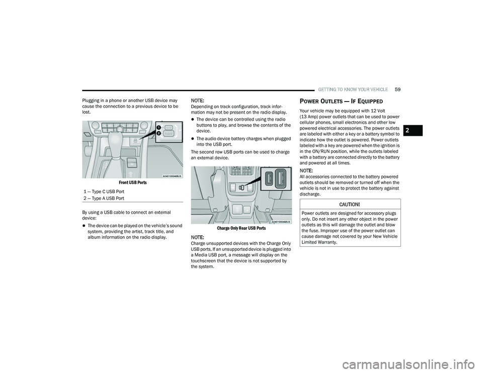
Front USB Ports
By using a USB cable to connect an external
device:
The device can be played on the vehicle’s sound
system, providing the artist, track title, and
album information on the radio display.
NOTE:Depending on track configuration, track infor -
mation may not be present on the radio display.
The device can be controlled using the radio
buttons to play, and browse the contents of the
device.
The audio device battery charges when plugged
into the USB port.
The second row USB ports can be used to charge
an external device.
Charge Only Rear USB Ports
NOTE:Charge unsupported devices with the Charge Only
USB ports. If an unsupported device is plugged into
a Media USB port, a message will display on the
touchscreen that the device is not supported by
the system.
POWER OUTLETS — IF EQUIPPED
Your vehicle may be equipped with 12 Volt
(13 Amp) power outlets that can be used to power
cellular phones, small electronics and other low
powered electrical accessories. The power outlets
are labeled with either a key or a battery symbol to
indicate how the outlet is powered. Power outlets
labeled with a key are powered when the ignition is
in the ON/RUN position, while the outlets labeled
with a battery are connected directly to the battery
and powered at all times.
NOTE:All accessories connected to the battery powered
outlets should be removed or turned off when the
vehicle is not in use to protect the battery against
discharge.
1 — Type C USB Port
2 — Type A USB Port
CAUTION!
Power outlets are designed for accessory plugs
only. Do not insert any other object in the power
outlets as this will damage the outlet and blow
the fuse. Improper use of the power outlet can
cause damage not covered by your New Vehicle
Limited Warranty.
2
22_MP_OM_EN_USC_t.book Page 59
Page 273 of 344
SERVICING AND MAINTENANCE271
ENGINE COMPARTMENT
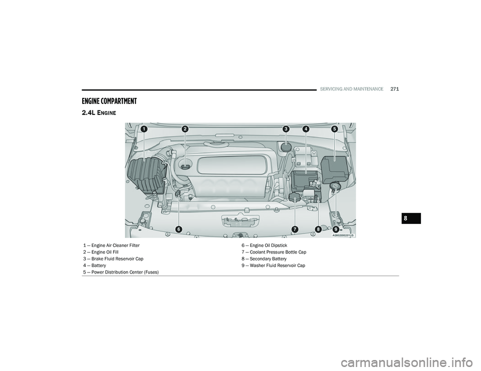
2.4L ENGINE
1 — Engine Air Cleaner Filter 6 — Engine Oil Dipstick
2 — Engine Oil Fill 7 — Coolant Pressure Bottle Cap
3 — Brake Fluid Reservoir Cap 8 — Secondary Battery
4 — Battery 9 — Washer Fluid Reservoir Cap
5 — Power Distribution Center (Fuses)
8
22_MP_OM_EN_USC_t.book Page 271
Page 286 of 344
284SERVICING AND MAINTENANCE
(Continued)
FUSES
General Information
The fuses protect electrical systems against
excessive current.
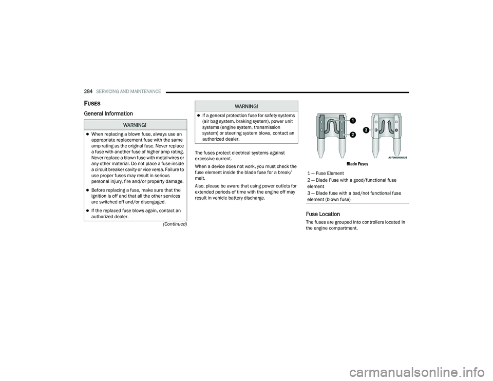
When a device does not work, you must check the
fuse element inside the blade fuse for a break/
melt.
Also, please be aware that using power outlets for
extended periods of time with the engine off may
result in vehicle battery discharge.
Blade Fuses
Fuse Location
The fuses are grouped into controllers located in
the engine compartment.
WARNING!
When replacing a blown fuse, always use an
appropriate replacement fuse with the same
amp rating as the original fuse. Never replace
a fuse with another fuse of higher amp rating.
Never replace a blown fuse with metal wires or
any other material. Do not place a fuse inside
a circuit breaker cavity or vice versa. Failure to
use proper fuses may result in serious
personal injury, fire and/or property damage.
Before replacing a fuse, make sure that the
ignition is off and that all the other services
are switched off and/or disengaged.
If the replaced fuse blows again, contact an
authorized dealer.
If a general protection fuse for safety systems
(air bag system, braking system), power unit
systems (engine system, transmission
system) or steering system blows, contact an
authorized dealer.
WARNING!
1 — Fuse Element
2 — Blade Fuse with a good/functional fuse
element
3 — Blade fuse with a bad/not functional fuse
element (blown fuse)
22_MP_OM_EN_USC_t.book Page 284
Page 287 of 344
SERVICING AND MAINTENANCE285
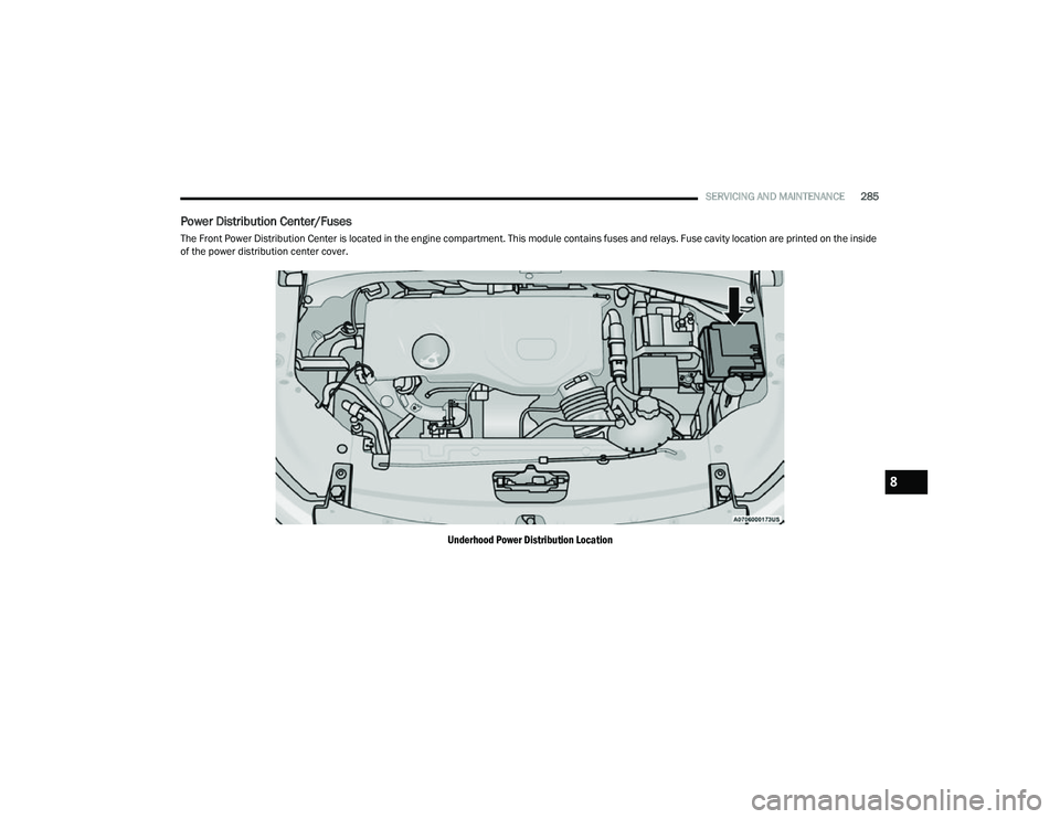
Power Distribution Center/Fuses
The Front Power Distribution Center is located in the engine compartment. This module contains fuses and relays. Fuse cavity location are printed on the inside
of the power distribution center cover.
Underhood Power Distribution Location
8
22_MP_OM_EN_USC_t.book Page 285
Page 288 of 344
286SERVICING AND MAINTENANCE
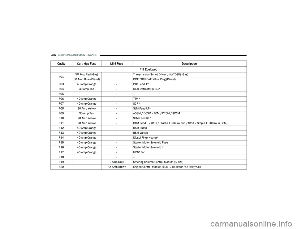
Cavity Cartridge Fuse Mini Fuse Description
* If Equipped
F01 50 Amp Red (Gas)
–Transmission Smart Driver Unit (TDSU) (Gas)
60 Amp Blue (Diesel) DCTT SDU BATT Glow Plug (Diesel)
F03 40 Amp Orange –PTC Feed 1*
F04 30 Amp Tan –Rear Defroster (EBL)*
F05 – ––
F06 40 Amp Orange –TTM*
F07 40 Amp Orange –SCR*
F08 20 Amp Yellow –SLM Feed LT*
F09 30 Amp Tan –AGSM / DCSM / TCM / DTCM / SCCM
F10 20 Amp Yellow –SLM Feed RT*
F11 20 Amp Yellow –BCM Feed 3 / (Run / Start & FB Relay and / Start / Stop & FB Relay in BCM)
F12 40 Amp Orange –BSM Pump
F13 40 Amp Orange –BSM Valves
F14 40 Amp Orange –Diesel Filter Heater*
F15 40 Amp Orange –Starter Motor Solenoid Fuse
F16 40 Amp Orange –Starter Motor Solenoid *
F17 40 Amp Orange –HVAC Fan
F18 – ––
F19 –2 Amp Grey Steering Column Control Module (SCCM)
F20 –7.5 Amp Brown Engine Control Module (ECM) / Radiator Fan Relay Coil
22_MP_OM_EN_USC_t.book Page 286
Page 289 of 344
SERVICING AND MAINTENANCE287
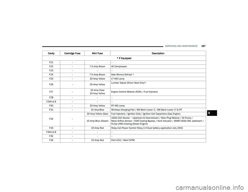
F21 – ––
F22 –7.5 Amp Brown AC Compressor
F23 – ––
F24 –7.5 Amp Brown Side Mirrors Defrost *
F25 –20 Amp Yellow LT HID Lamp
F26 –20 Amp Yellow Lumbar Adjust (Driver Seat Only)*
F27 –25 Amp Clear
20 Amp Yellow Engine Control Module (ECM) / Fuel Injectors
F28 – ––
F29A & B –––
F30 –20 Amp Yellow RT HID Lamp
F31 –15 Amp Blue Wireless Charging Pad / SW Bank Lower 2 / SW Bank Lower LT & RT
F32 –20 Amp Yellow (Gas) Fuel Injectors / Ignition Coils / Ignition Coil Capacitors (Gas Engine)
15 Amp Blue (Diesel) UEGO (02) Sensor – Upstream & Downstream / Glow Plug Module / Oil Pump /
Mass Airflow Sensor / EGR Cooling Bypass / Swirl Actuator / SNSR UEGO DSL Upstream /
Pump UREA Cooling (Diesel Engine)
F33 –10 Amp Red Relay Coil Power Control Relay 2.4 Dual battery application only (XHZ)
F34A & B –––
F35 – ––
F36 –10 Amp Red Port UCI2 / Mod CVPM
Cavity Cartridge Fuse Mini Fuse Description
* If Equipped
8
22_MP_OM_EN_USC_t.book Page 287
Page 290 of 344

288SERVICING AND MAINTENANCE
F37 – ––
F38 –10 Amp Red ECM / TCM / AGSM / DCSM / STM
F39 – ––
F40 – ––
F41 – ––
F42 –20 Amp Yellow Cargo Power Outlet – Ignition power
F43 – –Cargo Power Outlet (Can be replaced with 20 Amp fuse in F42 direct battery power)
F44 – ––
F45 – ––
F46 –30 Amp Tan Drivetrain Control Module (DTCM) AWD Power
F47 –30 Amp Tan Front Windshield Defrost*
F48 – ––
F49 –15 Amp Blue Transmission Control Module (TCM)
F50 –5 Amp Tan Drive Train Control Module (DTCM) ECU Power
F51 –20 Amp Yellow NOX SNSR Feed (Diesel Engine)
F52 –5 Amp Tan Automatic Gearbox Shifter Module (AGSM) (Diesel & Gas)
F53 – ––
F54 – ––
F55 – ––
F56 – ––
Cavity Cartridge Fuse Mini Fuse Description
* If Equipped
22_MP_OM_EN_USC_t.book Page 288
Page 291 of 344
SERVICING AND MAINTENANCE289
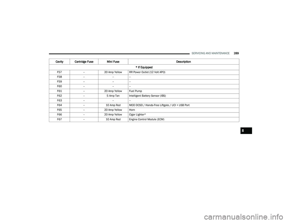
F57 –20 Amp Yellow RR Power Outlet (12 Volt APO)
F58 – ––
F59 – ––
F60 – ––
F61 –20 Amp Yellow Fuel Pump
F62 –5 Amp Tan Intelligent Battery Sensor (IBS)
F63 – ––
F64 –10 Amp Red MOD DCSD / Hands-Free Liftgate / UCI + USB Port
F65 –20 Amp Yellow Horn
F66 –20 Amp Yellow Cigar Lighter*
F67 –10 Amp Red Engine Control Module (ECM)
Cavity Cartridge Fuse Mini Fuse Description
* If Equipped
8
22_MP_OM_EN_USC_t.book Page 289
Page 292 of 344
290SERVICING AND MAINTENANCE
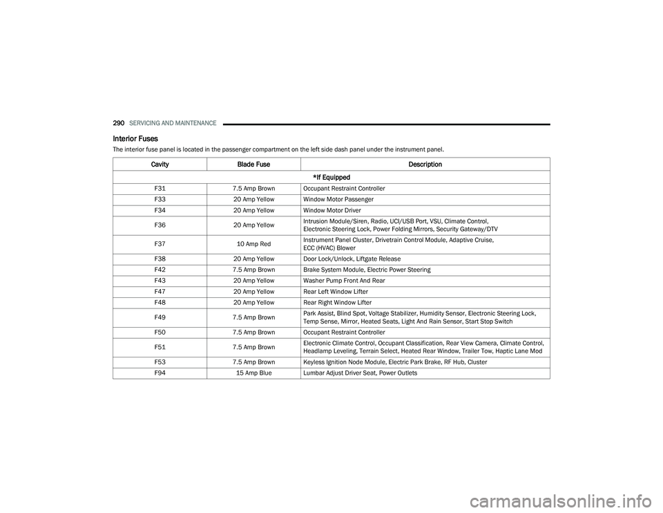
Interior Fuses
The interior fuse panel is located in the passenger compartment on the left side dash panel under the instrument panel.
CavityBlade Fuse Description
*If Equipped
F31 7.5 Amp Brown Occupant Restraint Controller
F33 20 Amp Yellow Window Motor Passenger
F34 20 Amp Yellow Window Motor Driver
F36 20 Amp YellowIntrusion Module/Siren, Radio, UCI/USB Port, VSU, Climate Control,
Electronic Steering Lock, Power Folding Mirrors, Security Gateway/DTV
F37 10 Amp RedInstrument Panel Cluster, Drivetrain Control Module, Adaptive Cruise,
ECC (HVAC) Blower
F38 20 Amp Yellow Door Lock/Unlock, Liftgate Release
F42 7.5 Amp Brown Brake System Module, Electric Power Steering
F43 20 Amp Yellow Washer Pump Front And Rear
F47 20 Amp Yellow Rear Left Window Lifter
F48 20 Amp Yellow Rear Right Window Lifter
F49 7.5 Amp BrownPark Assist, Blind Spot, Voltage Stabilizer, Humidity Sensor, Electronic Steering Lock,
Temp Sense, Mirror, Heated Seats, Light And Rain Sensor, Start Stop Switch
F50 7.5 Amp Brown Occupant Restraint Controller
F51 7.5 Amp BrownElectronic Climate Control, Occupant Classification, Rear View Camera, Climate Control,
Headlamp Leveling, Terrain Select, Heated Rear Window, Trailer Tow, Haptic Lane Mod
F53 7.5 Amp Brown Keyless Ignition Node Module, Electric Park Brake, RF Hub, Cluster
F94 15 Amp Blue Lumbar Adjust Driver Seat, Power Outlets
22_MP_OM_EN_USC_t.book Page 290