JEEP DJ 1953 Service Manual
Manufacturer: JEEP, Model Year: 1953, Model line: DJ, Model: JEEP DJ 1953Pages: 376, PDF Size: 19.96 MB
Page 131 of 376
'Jeep'
UNIVERSAL SERIES SERVICE
MANUAL
E
possibility of vapor lock by keeping cool fuel from
the tank constantly circulating through the fuel
pump.
Fuel
pump pressure at carburetor (inlet) on Daunt
less
V6-225
engine
should be 3% lbs.
[0,264
kgm-cm2] minimum at idle with the vapor return
hose
squeezed off. With the vapor return
hose
open
pump pressure should be 2j^ lbs. [0,176 kg-cm2]
minimum.
The
Dauntless V-6
engine
is equipped with a sealed
unit,
non-repairable, single-action fuel pump (Fig.
E-33).
Note:
All Dauntless V-6
engines
are equipped with
a
throw-away can-type gasoline filter installed in
the fuel line
between
the fuel pump and the
car
buretor.
This
unit must be replaced every
12,000
miles
[19.200
km.] of vehicle operation.
E-68.
Fuel
Pump Removal
To
remove the fuel pump from the Dauntless V-6
engine, disconnect the fuel inlet, fuel
outlet
and fuel return lines from the pump. Remove the two
fuel pump body attaching cap screws and lock
washers.
Pull
the fuel filter bracket free and remove the pump and gasket. Discard pump and gasket.
Install
new pump in reverse procedure of removal.
E-69.
AIR
CLEANER
Servicing
of the air cleaner is properly taken care of as part of the periodic lubrication and servicing of the vehicle. For this reason, air cleaner servicing
information is given in the Lubrication Section.
Refer
to and follow the instructions given there.
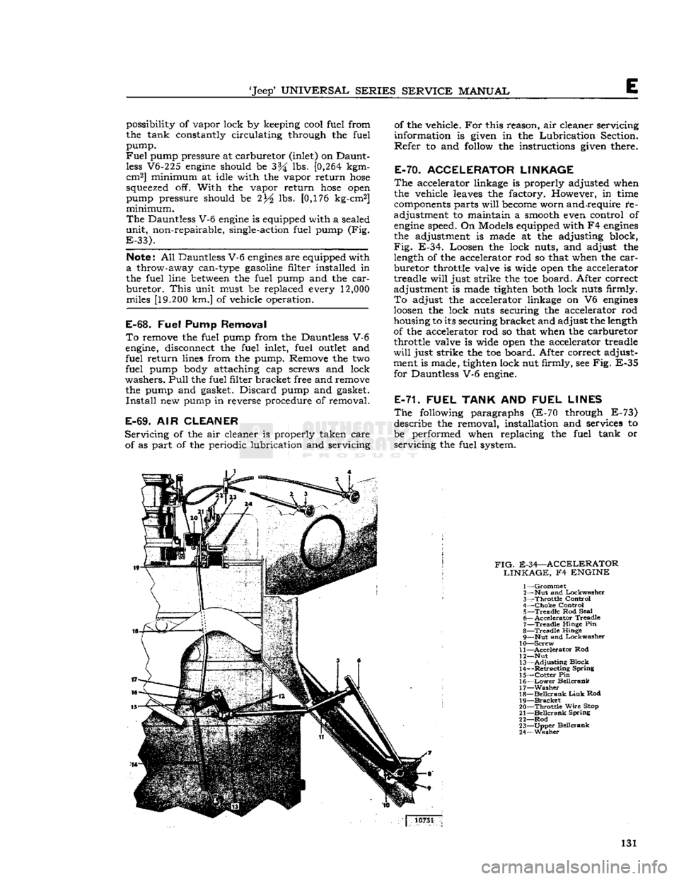
E-70. ACCELERATOR LINKAGE
The
accelerator linkage is properly adjusted when
the vehicle leaves the factory. However, in time
components parts
will
become
worn and require re
adjustment to maintain a smooth even control of
engine
speed. On Models equipped with F4
engines
the adjustment is made at the adjusting block,
Fig.
E-34. Loosen the lock nuts, and adjust the length of the accelerator rod so that when the
car
buretor throttle valve is wide open the accelerator
treadle
will
just strike the toe board. After correct
adjustment is made tighten both lock nuts firmly.
To
adjust the accelerator linkage on V6
engines
loosen
the lock nuts securing the accelerator rod
housing to its securing bracket and adjust the length
of the accelerator rod so that when the carburetor throttle valve is wide open the accelerator treadle
will
just strike the toe board. After correct adjust
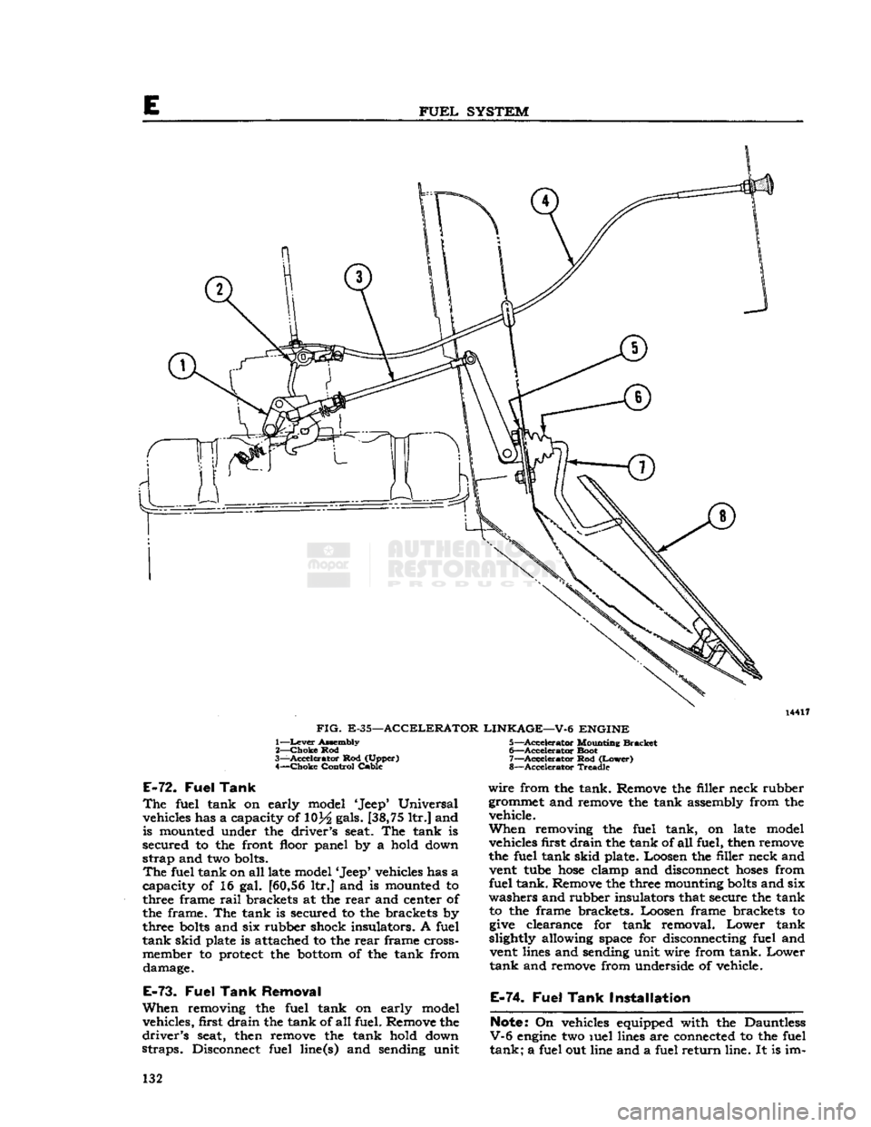
ment is made, tighten lock nut firmly, see Fig. E-35 for Dauntless V-6 engine.
E-71. FUEL
TANK
AND
FUEL LINES
The
following paragraphs (E-70 through E-73) describe the removal, installation and services to
be performed when replacing the fuel tank or
servicing
the fuel system.
FIG.
E-34—ACCELERATOR LINKAGE,
F4
ENGINE
1—
Grommet
2— Nut and Lockwasher
3—
Throttle
Control
4—
Choke
Control 5—
Treadle
Rod Seal
6—
Accelerator
Treadle
7—
Treadle
Hinge Pin
8—
Treadle
Hinge 9— Nut and Lockwasher
10—
Screw
11—
Accelerator
Rod
12— Nut
13—
Adjusting
Block
14—
Retracting
Spring
15—
Cotter
Pin
16—
Lower
Beilcrank
17—
Washer
18—
Beilcrank
Link
Rod
19—
Bracket
20—
Throttle
Wire
Stop
21—
Beilcrank
Spring
22—
Rod
23—
Upper
Beilcrank
24—
Wesher
10731
131
Page 132 of 376
FUEL
SYSTEM
14417
FIG.
E-35—ACCELERATOR LINKAGE—V-6 ENGINE
1— Lever
Assembly
2—
Choke
Rod
3—
-Accelerator
Rod (Upper) 4—
Choke
Control Cable
E-72.
Fuel
Tank
The
fuel tank on early model 'Jeep* Universal vehicles has a capacity of 10}4 gals. [38,75 ltr.] and
is mounted under the driver's seat. The tank is
secured to the front floor panel by a hold down
strap
and two bolts.
The
fuel tank on all late model 'Jeep* vehicles has a
capacity of 16 gal. [60,56 ltr.] and is mounted to
three frame
rail
brackets at the
rear
and center of
the frame. The tank is secured to the brackets by
three
bolts
and six rubber shock insulators. A fuel
tank
skid plate is attached to the
rear
frame cross- member to protect the
bottom
of the tank from damage.
E-73.
Fuel
Tank
Removal
When
removing the fuel tank on early model vehicles, first drain the tank of
all
fuel. Remove the
driver's
seat, then remove the tank hold down
straps.
Disconnect fuel line(s) and sending unit 5—
Accelerator
Mounting Bracket
6—
-Accelerator
Boot
7—
Accelerator
Rod
(Lower)
8—
Accelerator
Treadle
wire
from the tank. Remove the filler neck rubber
grommet and remove the tank assembly from the vehicle.
When
removing the fuel tank, on late model vehicles first
drain
the tank of
all
fuel, then remove
the fuel tank skid plate. Loosen the filler neck and vent tube
hose
clamp and disconnect
hoses
from fuel tank. Remove the three mounting
bolts
and six
washers and rubber insulators that secure the tank to the frame brackets. Loosen frame brackets to
give
clearance for tank removal.
Lower
tank
slightly allowing space for disconnecting fuel and vent lines and sending unit wire from tank.
Lower
tank
and remove from underside of vehicle.
E-74.
Fuel Tank Installation
Note:
On vehicles equipped with the Dauntless
V-6
engine
two luel lines are connected to the fuel
tank;
a fuel out line and a fuel return line. It is im- 132
Page 133 of 376
'Jeep'
UNIVERSAL
SERIES
SERVICE
MANUAL
E
portant that
these
lines are not accidentally re
versed.
When
installing the fuel tank on late model vehicles, position the tank
between
the frame
rail
to allow space to connect the fuel line(s), vent
hose
and
sending unit wire. After connecting
these
items, align and secure tank to frame brackets.
Position filler
hose
on tank filler neck and tighten
hose
clamp.
Fill
tank with fuel and check for leaks.
When
installing the fuel tank on early model vehicles, reverse the order of removal as given in
Par.
E-73.
E-75.
Fuel
Tank
Cap
A
surge pressure type fuel tank filler cap is used on
all
models.
This
is necessary to prevent fuel leakage
from
the cap vent opening when the vehicle is on a
side slope. Two spring loaded relief valves which
open when venting is required are built into the
cap.
Should the pressure valve
fail
to open, pressure
in
the tank may force fuel by the carburetor inlet
valve causing flooding.
Failure
of the vacuum valve may prevent flow of fuel to the carburetor. Should
the valves
fail
to vent install a new cap.
Note:
Vehicles having a
Fuel
Evaporative
Emis
sion System are equipped with a non-vent sealed gas cap. The sealed cap is designed to allow no
vapors to discharge to the atmosphere. No other type of cap is to be used on vehicles having this
type system.
E-76.
Fuel
Gauge Float Unit
The
fuel tank
gauge
float unit is mounted in the top
of the fuel tank and consists of a housing enclosing
a
rheostat that is actuated by the float arm, and a
float
which
moves
with the fuel level in the tank.
On
V-6 and current production F4
engine
equipped vehicles, the fuel
outlet
pipe is integral with the
float
unit.
The fuel
outlet
pipe has a mesh filter on the inner end.
Note:
Under no circumstances should a fuel tank
gauge
be installed without a mesh filter element.
The
filter,
outlet
pipe, and float unit are locked as
an
assembly to the top of the fuel tank. To remove,
turn
the lock plate that secures the float unit
assembly.
E-77.
Fuel
Lines
Check
lines and connections occasionally for leaks,
and
for severe kinks that might restrict the flow of
fuel. If an excessive amount of
dirt
is found in the
carburetor
or fuel pump, the fuel tank should be
drained
and the fuel lines blown out with com
pressed air.
All
rubber fuel lines and their respective clamps should be checked occasionally to be certain they
are
correctly positioned and not leaking. 133
Page 134 of 376
E
FUEL
SYSTEM
E-78. SERVICE DIHGNOSIS
Symptoms Probable Remedy
Excessive
Fuel
Consumption:
Tires
improperly inflated Inflate
Brakes
drag Adjust
Engine
operates too cold Check thermostat
Heat control valve inoperative Check thermostatic spring
Leak
in fuel line Check all connections
Carburetor
float level high. See
"Carburetor"
section
Accelerator pump not properly adjusted Adjust
Leaky
fuel pump diaphragm Replace
Loose
engine
mountings causing high carburetor fuel level Tighten Ignition timing slow or spark advance stuck See "Distributor" section
Low
compression. Check valve tappet clearance
Air
cleaner dirty
.
Remove and clean
Engine
Hesitates on Acceleration: Accelerator pump
does
not function perfectly.
...................
.Replace piston and rod or adjust
Carburetor
float level. ... .Adjust
Spark
plugs Replace or clean and adjust
Low
compression Check valves
Distributor
points—dirty or pitted Replace
Weak
condenser or coil Replace
Carburetor
jets restricted Remove and clean
Excessive
engine
heat See "Engine" section
Engine
Stalls—Won't Idle:
Improper
condition of carburetor See
"Carburetor"
section
Low
speed
jet restricted Remove and clean
Dirty
fuel sediment bowl screen Remove and clean
Air
cleaner dirty Remove and clean
Leaky
manifold or gasket Replace
Fuel
pump diaphragm porous. Replace
Loose carburetor. Tighten
flange
nuts
Water
in fuel
Drain
and clean system
Improper
ignition. .See "Distributor" section
Spark
plugs Clean and adjust
Valves
sticking.
Grind
valves 134
Page 135 of 376
'Jeep'
UNIVERSAL SERIES
SERVICE
MANUAL
E
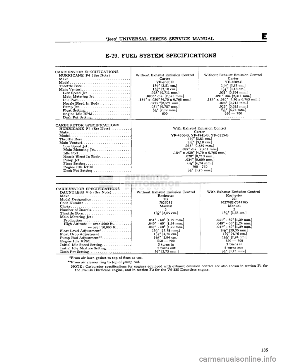
E-79.
FUEL
SYSTEM SPECIFICHTIONS
CARBURETOR SPECIFICATIONS HURRICANE
F4 (See
Note)
Make
Model.
Throttle Bore
Main
Venturi.
Low
Speed
Jet
Main
Metering Jet Idle Port
Nozzle
Bleed In Body
Pump Jet
Float
Setting
Engine Idle RPM Dash Pot
Setting
. ......
CARBURETOR SPECIFICATIONS HURRICANE
F4 (See
Note).
Make Model
Throttle Bore
Main
Venturi
Low
Speed
Jet
Main
Metering Jet Idle Port
Nozzle
Bleed In Body
Pump Jet.
Float
Setting
Engine Idle RPM Dash Pot
Setting
Without Exhaust Emission Control
Carter
YF-938SD
lY2n
[3,81 cm.]
1M"
[3,18 cm.]
.028"
[0,711
mm.]
.0935"
dia.
[2,375
mm.]
.184" x .030" [4,70 a
0,765
mm.]
.0225
"[0,571
mm.] .031"
[0,787
mm.] Vk" [7,39 mm.] 600 Without Exhaust Emission Control
Carter
YF-4002-S
\y%"
[3,81 cm.]
1M"
[3,18 cm.]
.031"
[0,794
mm.]
.091" dia.
[2,311
mm.]
.184" x .030" [4,70 a
0.765
mm.] .028"
[0,713
mm.]
.025"
[0,635
mm.]
lW
[6,74 mm.] 650 — 700
With
Exhaust Emission Control
Carter
YF-4366-S,
YF-4941-S, YF-6115-S IV2" [3,81 cm.]
1M*
[3,18 cm.]
.035"
[0,889
mm.]
.089" dia.
[2,261
mm.]
.184" x .030" [4,70 a
0.765
mm.] .028"
[0,713
mm.]
.024"
[0,609
mm.]
1W
[6,74 mm.] 700 - 750
Y%" ]3,75 mm.]
CARBURETOR SPECIFICATIONS
DAUNTLESS
V-6 (See
Note)
Make
Model
Designation
Code Number
Choke
Number of Barrels
Throttle Bore
Main
Metering Jet: Production . . High Altitude —
over
5000
ft
—
over
10,000
ft... .
Float Level Adjustment*
Float Drop Adjustment Pump Rod Adjustment**
Engine Idle RPM
Initial
Idle
Speed
Setting
Initial
Idle Mixture
Setting.
Dash Pot
Setting
Without Exhaust Emission Control
Rochester
2G
7026082
Manual
2
Wy? [3,65 cm.]
.051" - 60° [1,29 mm.]
.049" - 60° [1,24 mm.] .047" - 60° [1,29 mm.]
Hit"
[27,78
mm.] V/%" [4,76 cm.]
IH2"
J2.94 cm.] 650
-—
700 3 turns in
2 turns out
W [3,75 mm.]
With
Exhaust Emission Control
Rochester
2G
7027082-7041185
Manual
2
[3,65 cm.]
.051" - 60° [1,29 mm.]
.049" - 60° [1,24 mm.] .047" - 60° (1,29 mm.] l%2"
[29,36
mm.] V/£" [4,76 cm.]
\W
]2,94 cm.[ 650 — 700 3 turns in
2 turns out
[3,75 mm.]
*From
air horn
gasket
to top of
float
at toe.
**From
air cleaner ring to top of
pump
rod.
NOTE:
Carburetor
specifications
for
engines
equipped
with
exhaust
emission
control are
also
shown
in
section
Fl for the F4-134 Hurricane
engine,
and in
section
F2 for the V6-225 Dauntless
engine.
135
Page 136 of 376
E
FUEL
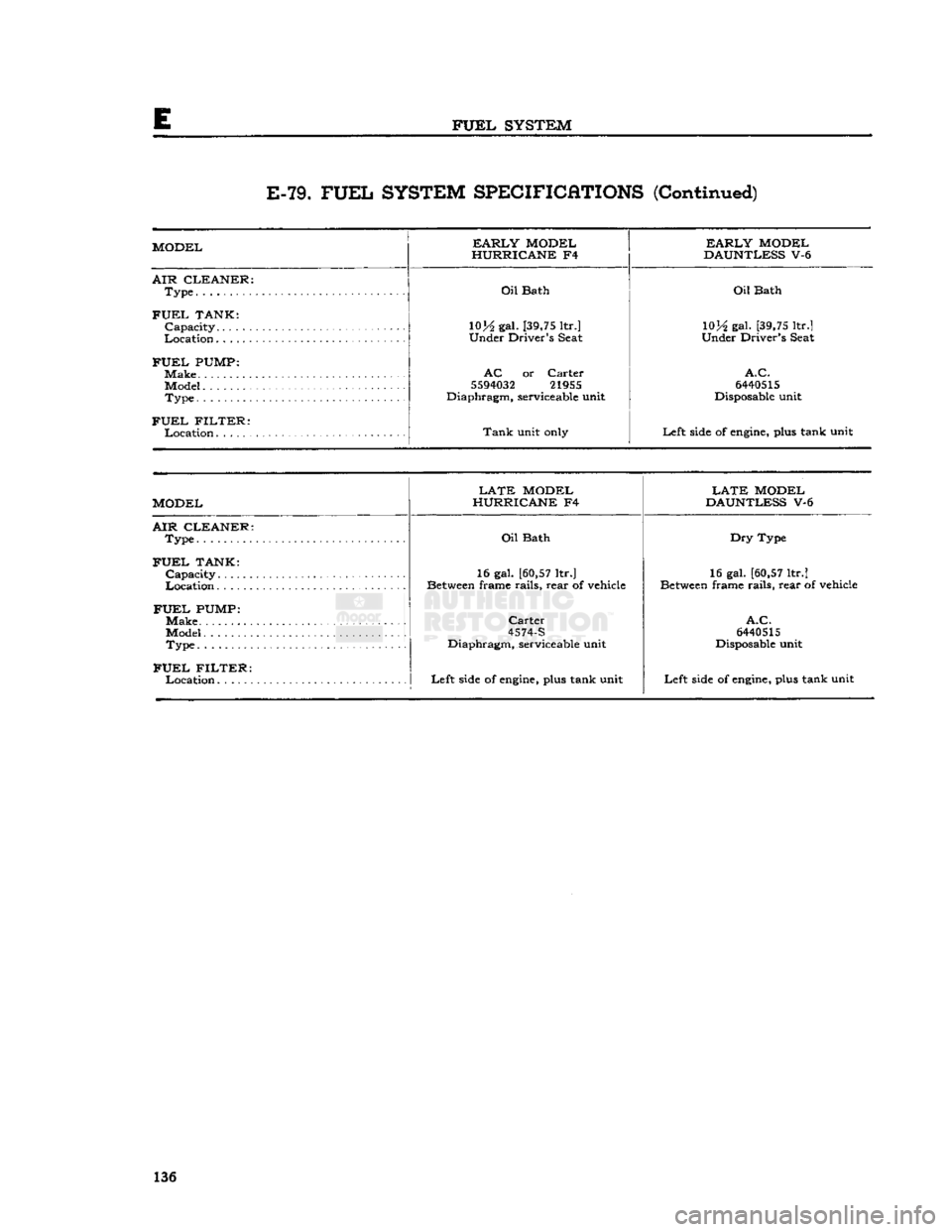
SYSTEM E-79.
FUEL
SYSTEM SPECIFICATIONS
(Continued)
MODEL
EARLY
MODEL
HURRICANE
F4
EARLY
MODEL
DAUNTLESS
V-6
AIR CLEANER:
Type
Oil
Bath
Oil
Bath
FUEL
TANK: 10H
gal. [39,75 ltr.]
10lA
gal. [39,75 ltr.]
Location
Under
Driver's Seat
Under
Driver's Seat
FUEL
PUMP:
AC
or
Carter
A.C.
Model
5594032
21955
6440515
Type..
Diaphragm,
serviceable unit
Disposable unit
FUEL
FILTER:
Tank
unit only
Left
side of engine, plus tank unit
MODEL
LATE
MODEL
HURRICANE
F4
LATE
MODEL
DAUNTLESS
V-6
AIR CLEANER:
Type...
Oil
Bath
Dry
Type
FUEL
TANK:
Capacity
16 gal. [60,57 ltr.]
16 gal. [60,57 ltr.]
Between frame
rails,
rear
of vehicle Between frame
rails,
rear
of vehicle
FUEL
PUMP:
Make.
Carter
A.C.
Model.
. 4574-S
6440515
Type
Diaphragm,
serviceable unit
Disposable unit
FUEL
FILTER:
Left
side of engine, plus tank unit
Left
side of engine, plus tank unit 136
Page 137 of 376
'Jeep*
UNIVERSAL SERIES SERVICE
MANUAL
F EXHAUST SYSTEM
Contents
SUBJECT
PAR.
GENERAL
.F-l Dauntless V-6 Engine Exhaust System....
F-3
Hurricane
F4 Engine Exhaust System....
F-2
MAINTENANCE
REQUIREMENTS
F-4
EXHAUST SYSTEM SERVICING
F-5
SUBJECT
PAR.
Exhaust
Manifold Installation. .F-6
Exhaust
Pipe(s) Replacement F-8
Heat
Control Valve Replacement F-7
Muffler
Replacement F-9
Tail
Pipe Replacement F-10
EXHAUST SYSTEM SPECIFICATIONS.
.
F-11
F-L
GENERAL
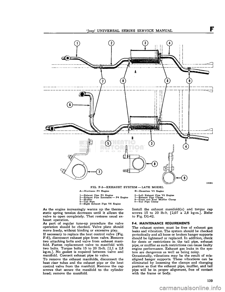
The
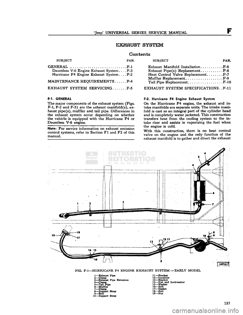
major components of the exhaust system (Figs.
F-l,
F-2 and F-3) are the exhaust manifold(s), ex
haust pipe(s), muffler and tail pipe. Differences in
the exhaust system occur depending on whether the vehicle is equipped with the Hurricane F4 or
Dauntless V-6 engine.
Note:
For service information on exhaust emission
control systems, refer to Section Fl and F2 of this
manual.
F-2. Hurricane
F4 Engine Exhaust System
On
the Hurricane F4 engine, the exhaust and in
take manifolds are separate units. The intake mani
fold is cast as an integral part of the cylinder head
and
is completely water jacketed.
This
construction
transfers
heat from the cooling system to the in
take riser and assists in vaporizing the fuel when
the
engine
is cold.
With
this construction, there is no heat control
valve on the
engine
and the only function of the exhaust manifold is to gather and direct the exhaust
FIG.
F-l—HURRICANE F4 ENGINE EXHAUST
SYSTEM
—
EARLY
MODEL
1—
Exhaust
Pipe
2—
Clamp
3—
Exhaust
Pipe Extension
4—
Clamp
5— Tail
Pipe 6—
Muffler
7—
Clamp
8—
Support
Strap
9—Bolt
10—Support
Strap
11—Bracket
12—
Insulator
13—
Bracket
14—
Nut
and
Lockwasher
15—
Washer
16—Bolt
17—
Gasket
18—
Bolt
19— Nut
137
Page 138 of 376
F
EXHAUST
SYSTEM
12844
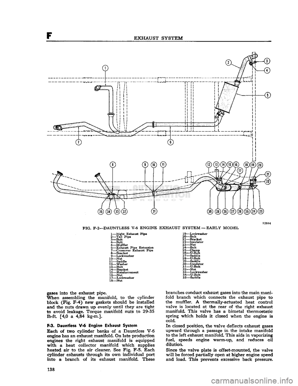
FIG.
F-2—DAUNTLESS
V-6
ENGINE
EXHAUST
SYSTEM
—
EARLY
MODEL
1—
Right
Exhaust
Pipe
19—Lockwasher
2—Tall
Pipe 20—Bolt
3—
Bolt
21—Bracket
4—
Bolt
22—Insulator
5—
Muffler
23—Nut 6—
Exhaust
Pipe
Extension
24—Bolt
7—
Crossover
Exhaust
Pipe
25—Clamp
8—
Bracket
26—U-Bolt 9—
Lockwasher
27—Saddle
10—
Nut
28—U-Bolt
11—
Saddle
29—Saddle
12—
Washer
30—Insulator
13—Bolt
31—U-Bolt
14—
Bracket
32—Nut
15—
Reinforcement
3
3—Lockwasher
16—
Nut
34—U-Bolt
17—
Lockwasher
35—Saddle
18—
Nut
gases
into the exhaust pipe.
When
assembling the manifold, to the cylinder
block
(Fig.
F-4)
new gaskets should be installed
and
the nuts drawn up evenly until they are tight
to avoid leakage. Torque manifold nuts to 29-35 lb-ft [4,0 a 4,84 kg-m.].
F-3.
Dauntless
¥-6
Engine
Exhaust System
Each
of two cylinder banks of a Dauntless V-6 engine has an exhaust manifold. On late production engines the right exhaust manifold is equipped
with
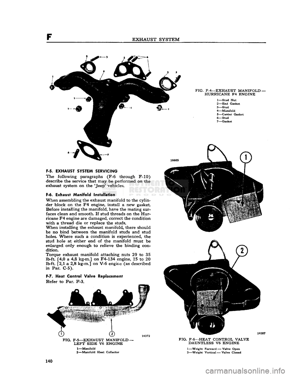
a heat collector manifold which supplies heated air to the air cleaner. See Fig. F-5.
Each
cylinder
exhausts through its own individual port
into a branch of its exhaust manifold. These
branches
conduct exhaust
gases
into the main mani
fold branch which connects the exhaust pipe to
the muffler. A thermally-actuated heat control valve is located at the
rear
of the right exhaust
manifold.
This
valve has a bimetal thermostatic
spring
which holds it closed when the engine is
cold.
In
closed position, the valve deflects exhaust
gases
upward
through a passage in the intake manifold to the left exhaust manifold.
This
aids in vaporizing
fuel,
speeds
engine warm-up, and reduces oil
dilution.
Since
the valve plate is offset-mounted, the valve
will
be forced partially open at higher engine speed
and
load.
This
prevents excessive back pressure. 138
Page 139 of 376
'Jeep'
UNIVERSAL
SERIES
SERVICE
MANUAL
©
1
1
©-
IT
T"
I
FIG.
F-3—EXHAUST SYSTEM —
LATE
MODEL
A—Hurricane
F4 Engine B—Dauntless V6 Engine
1—
Exhaust
Pipe F4 Engine
2—
Exhaust
Pipe
Extension
— F4 Engine
3—
Muffler
4—
Tail
Pipe
5—
Right
Exhaust
Pipe V6 Engine
As
the
engine
increasingly warms up the thermo static spring tension decreases until it allows the
valve to open completely.
That
restores usual ex haust operation.
As
part of regular tune-up procedure the valve operation should be checked. Valve plate should
move
freely, without binding or excessive play.
If
necessary to replace the heat control valve (Fig.
F-6),
disconnect exhaust pipe from valve. Remove
two attaching
bolts
and valve from exhaust mani
fold. Fasten replacement valve to manifold with two bolts. Torque
bolts
15 to 20 lb-ft [2,1 a 2,8
kg-m.].
No gasket is required
between
valve and manifold. Connect exhaust pipe to valve.
To
remove the exhaust manifolds, disconnect the heat riser
tubes
and the exhaust pipe or the heat
control valve from the manifold. Remove the cap screws that secure the manifold to the cylinder
head; remove the manifold. 6—
Left
Exhaust
Pipe V6 Engine
7—
Exhaust
Pipe
Clamp
8—
Front
and
Rear
Muffler
Clamp
9—
Tail
Pipe
Clamp
Install
the exhaust manifold(s) and torque cap
screws 15 to 20 lb-ft. [2,07 a 2,8 kg-m.]. Refer
to Fig. Dl-42.
F-4.
MAINTENANCE REQUIREMENTS
The
exhaust system must be free of exhaust gas leaks and vibration. The system should be checked periodically and all
loose
or broken hanger supports
should be tightened or replaced. In addition, check
for
dents
or restrictions in the tail pipe, exhaust pipe, or muffler as such restrictions can cause faulty
engine
performance. Exhaust gas leaks in the sys
tem are dangerous as well as being noisy.
Occasionally,
vibrations may be the result of mis
aligned hanger supports. These vibrations can be
eliminated by loosening the clamps and changing position so that the exhaust pipe, muffler, and tail
pipe
will
be in proper alignment, free of contact
with
the frame or body. 139
Page 140 of 376
F
EXHAUST SYSTEM
FIG.
F-4—EXHAUST MANIFOLD-HURRICANE
F4
ENGINE
1—
Stud
Nut
2—
End
Gasket
3—
Stud
4—
Manifold
5—
Center
Gasket
6—
Stud
7—
Gasket
F-5.
EXHAUST SYSTEM SERVICING
The
following paragraphs (F-6 through F-10)
describe the service that may be performed on the
exhaust system on the 'Jeep' vehicles.
F-6.
Exhaust Manifold Installation
When
assembling the exhaust manifold to the cylin der block on the F4 engine, install a new gasket. Before installing the manifold, have the mating
sur
faces clean and smooth. If stud threads on the
Hur
ricane
F4
engine
are damaged, correct the condition
with
a thread die or replace the studs.
When
installing the exhaust manifold, there should
be no bind
between
the manifold studs and stud
holes. Where such a condition is experienced, the stud
hole
at either end of the manifold must be
enlarged only enough to relieve the binding con
dition.
Torque
exhaust manifold attaching nuts 29 to 35 lb-ft. [4,0 a 4,8 kg-m.] on F4-134 engine, 15 to 20
lb-ft. [2,1 a 2,8 kg-m.] on V-6
engine
(as described
in
Par. C-5).
F-7.
Heat
Control Valve Replacement
Refer
to Par. F-3.
FIG.
F-5—EXHAUST MANIFOLD
-
LEFT
SIDE
V6
ENGINE
1—
Manifold
2—
Manifold
Heat Collector
J666S
14287
FIG.
F-6—HEAT CONTROL
VALVE
DAUNTLESS
V6
ENGINE
1— Weight
Forward
— Valve Open
2— Weight
Vertical
— Valve Closed 140