wheel JEEP DJ 1953 Owner's Manual
[x] Cancel search | Manufacturer: JEEP, Model Year: 1953, Model line: DJ, Model: JEEP DJ 1953Pages: 376, PDF Size: 19.96 MB
Page 65 of 376
'Jeep'
UNIVERSAL
SERIES
SERVICE
MANUAL
D
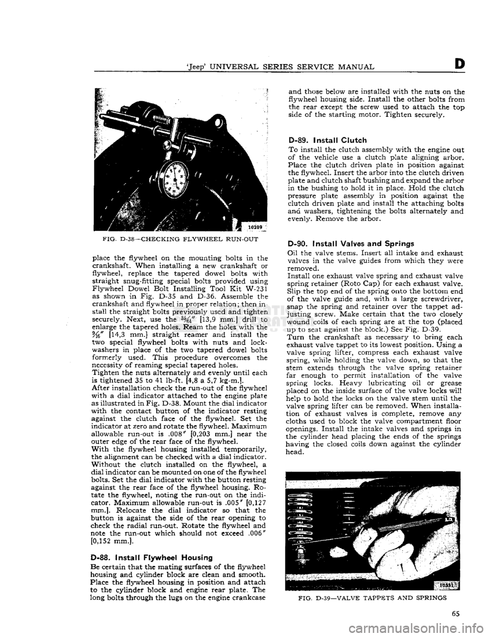
FIG.
D-38—CHECKING
FLYWHEEL
RUN-OUT
place the flywheel on the mounting
bolts
in the
crankshaft.
When installing a new crankshaft or
flywheel, replace the tapered dowel
bolts
with
straight snug-fitting special
bolts
provided using
Flywheel
Dowel Bolt Installing Tool Kit W-231 as shown in Fig. D-35 and D-36. Assemble the
crankshaft
and flywheel in proper relation; then in
stall
the straight
bolts
previously used and tighten
securely. Next, use the [13,9 mm.]
drill
to
enlarge the tapered holes. Ream the
holes
with the 5fo" [14,3 mm.] straight reamer and install the
two special flywheel
bolts
with nuts and lock
washers in place of the two tapered dowel
bolts
formerly
used.
This
procedure overcomes the
necessity of reaming special tapered holes.
Tighten
the nuts alternately and evenly until each
is tightened 35 to 41 lb-ft. [4,8 a 5,7 kg-m.].
After
installation check the run-out of the flywheel
with
a
dial
indicator attached to the
engine
plate
as illustrated in
Fig.
D-38. Mount the
dial
indicator
with
the contact button of the indicator resting against the clutch face of the flywheel. Set the
indicator
at zero and rotate the flywheel. Maximum
allowable run-out is .008"
[0,203
mm.] near the
outer
edge
of the
rear
face of the flywheel.
With
the flywheel housing installed temporarily,
the alignment can be checked with a
dial
indicator. Without the clutch installed on the flywheel, a
dial
indicator can be mounted on one of the flywheel bolts. Set the
dial
indicator with the button resting
against the
rear
face of the flywheel housing. Ro
tate
the flywheel, noting the run-out on the
indi
cator.
Maximum allowable run-out is .005" [0,127
mm.].
Relocate the
dial
indicator so that the
button is against the side of the
rear
opening to
check the
radial
run-out. Rotate the flywheel and
note
the run-out which should not exceed .006" [0,152 mm.].
D-88.
Install
Flywheel Housing
Be
certain that the mating surfaces of the flywheel housing and cylinder block are clean and smooth.
Place
the flywheel housing in position and attach to the cylinder block and
engine
rear
plate. The
long
bolts
through the lugs on the
engine
crankcase
and
those
below are installed with the nuts on the
flywheel housing side.
Install
the other
bolts
from
the
rear
except the screw used to attach the top
side of the starting motor. Tighten securely.
D-89.
Install
Clutch
To
install the clutch assembly with the
engine
out
of the vehicle use a clutch plate aligning arbor.
Place
the clutch driven plate in position against
the flywheel. Insert the arbor into the clutch driven plate and clutch shaft bushing and expand the arbor
in
the bushing to hold it in place. Hold the clutch
pressure plate assembly in position against the
clutch
driven plate and install the attaching
bolts
and
washers, tightening the
bolts
alternately and
evenly. Remove the arbor.
D-90.
Install
Valves and Springs
Oil
the valve stems. Insert all intake and exhaust valves in the valve
guides
from which they were
removed.
Install
one exhaust valve spring and exhaust valve
spring
retainer (Roto Cap) for each exhaust valve.
Slip
the top end of the spring
onto
the
bottom
end
of the valve guide and, with a large screwdriver,
snap the spring and retainer over the tappet ad
justing
screw. Make certain that the two closely wound coils of each spring are at the top (placed up to seat against the block.) See Fig. D-39.
Turn
the crankshaft as necessary to bring each
exhaust valve tappet to its lowest position. Using a
valve spring lifter, compress each exhaust valve
spring,
while holding the valve down, so that the
stem
extends
through the valve spring retainer
far
enough to permit installation of the valve
spring
locks. Heavy lubricating oil or grease
placed on the inside surface of the valve locks
will
help to hold the locks on the valve stem until the valve spring lifter can be removed. When installa
tion of exhaust valves is complete, remove any
cloths used to block the valve compartment floor
openings.
Install
the intake valves and springs in the cylinder head placing the ends of the springs
having the closed coils down against the cylinder
head.
FIG.
D-39—VALVE
TAPPETS
AND
SPRINGS
65
Page 68 of 376
D
HURRICANE
F4
ENGINE
D-101.
Install
Manifold
If
manifold studs were removed for replacement,
apply sealer on the stud threads
before
installing
a
new stud.
See Section Fl for exhaust emission controlled
engines.
Make
certain that no foreign objects are inside the manifold and that all
passages
are clear. Place a
new set of manifold
gaskets
in position on the side
of the cylinder block.
Then,
carefully slide the manifold
onto
the studs and against the cylinder block being careful not to damage the gaskets.
Torque
all manifold attaching nuts evenly 29 to
35 lb-ft. [4,0 a 4,8 kg-m.].
D-102.
Install
Oil
Filler
Tube
When
installing the oil filler tube, be sure that the
beveled lower end is away from the crankshaft.
Place a
piece
of
hard
wood
over the top of the
tube
to prevent damage to the cap gasket seat.
D-103.
Install
Water Pump
Make
certain that the mating surfaces of the water pump and the cylinder block are clean and smooth.
Install
the gasket on the
flange
of the pump and
install
the pump in position on the cylinder block.
Torque
the water pump attaching
bolts
alternately
and
evenly 12 to 17 lb-ft. [1,7 a 2,3 kg-m.].
D-104.
Install
Water Outlet Fitting
Install
the thermostat and the water
outlet
fitting.
Torque
the water
outlet
fitting attaching
bolts
20
to 25 lb-ft. [2,8 a 3,4 kg-m.].
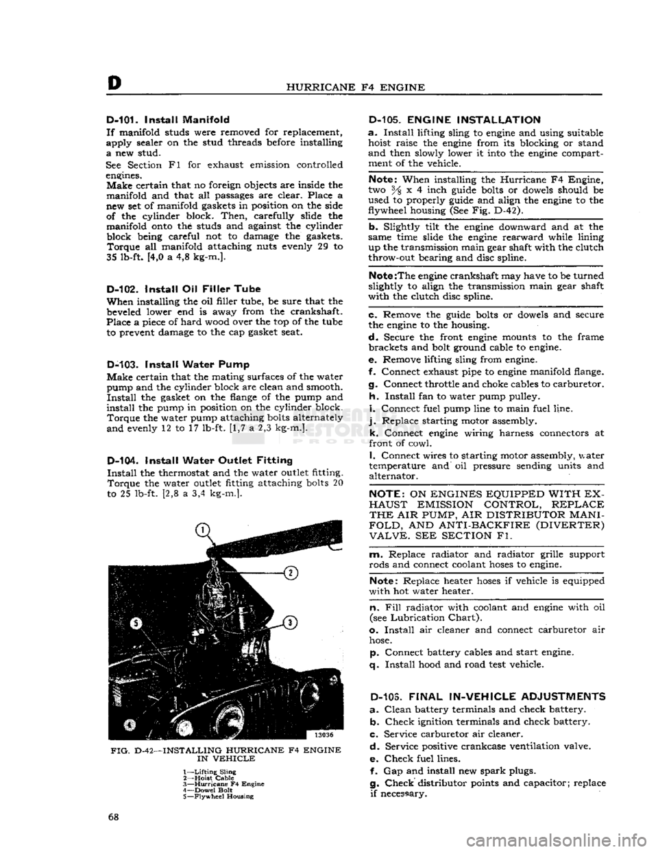
FIG.
D-42—INSTALLING HURRICANE F4 ENGINE
IN
VEHICLE
1—
Lifting
Sling
2— Hoist
Cable
3—
Hurricane
F4 Engine
4— Dowel Bolt
5—
Flywheel
Housing
D-105.
ENGINE INSTALLATION
a.
Install
lifting sling to
engine
and using suitable hoist raise the
engine
from its blocking or stand
and
then slowly lower it
into
the
engine
compartment of the vehicle.
Note:
When installing the
Hurricane
F4 Engine,
two % x 4 inch
guide
bolts
or
dowels
should be
used to properly
guide
and align the
engine
to the
flywheel housing (See Fig. D-42).
b. Slightly tilt the
engine
downward and at the
same time slide the
engine
rearward
while lining up the transmission main gear shaft with the clutch
throw-out bearing and disc spline.
Note
:The
engine
crankshaft may have to be turned
slightly to align the transmission main gear shaft
with the clutch disc spline.
c. Remove the
guide
bolts
or
dowels
and secure
the
engine
to the housing.
d.
Secure the front
engine
mounts to the frame brackets and
bolt
ground cable to
engine.
e. Remove lifting sling from
engine.
f. Connect exhaust pipe to
engine
manifold flange.
g. Connect throttle and choke cables to carburetor.
h.
Install
fan to water pump pulley.
i.
Connect fuel pump line to main fuel line,
j.
Replace starting motor assembly. k. Connect
engine
wiring harness connectors at
front of cowl.
I.
Connect wires to starting motor assembly, water
temperature and oil pressure sending units and alternator.
NOTE:
ON
ENGINES EQUIPPED WITH EX
HAUST
EMISSION CONTROL,
REPLACE
THE
AIR
PUMP,
AIR
DISTRIBUTOR
MANI
FOLD,
AND
ANTI-BACKFIRE (DIVERTER)
VALVE.
SEE
SECTION
Fl.
m. Replace radiator and radiator grille support
rods and connect coolant
hoses
to
engine.
Note:
Replace heater
hoses
if vehicle is equipped
with hot water heater.
n. Fill
radiator with coolant and
engine
with oil
(see
Lubrication
Chart).
o.
Install
air cleaner and connect carburetor air
hose.
p. Connect battery cables and start
engine,
q.
Install
hood
and road
test
vehicle.
D-103.
FINAL
IN-VEHICLE
ADJUSTMENTS
a.
Clean
battery terminals and check battery. b.
Check
ignition terminals and check battery.
c. Service carburetor air cleaner.
d.
Service positive crankcase ventilation valve.
e.
Check
fuel lines. f. Gap and install new
spark
plugs.
g.
Check
distributor
points
and capacitor; replace
if
necessary. 68
Page 70 of 376
D
HURRICANE
F4
ENGINE
D-112.
SERVICE
DIAGNOSIS
Poor
Fuel
Economy Ignition Timing Slow or Spark Advance Stuck
Carburetor
Float High
Accelerator Pump Not Properly Adjusted
High
Fuel
Pump Pressure
Fuel
Leakage
Leaky
Fuel
Pump Diaphragm
Loose Engine Mounting Causing High
Fuel
Level
in
Carburetor
Low
Compression Valves Sticking
Spark
Plugs Bad
Spark
Plug Cables Bad Weak
Coil
or Condenser Improper Valve Tappet Clearance
Carburetor
Air Cleaner Dirty
High Oil Level in Air Cleaner Dragging Brakes
Front
Wheels Out of Alignment
Tires
Improperly Inflated Inaccurate Odometer
Faulty
Fuel
Tank
Cap
Clogged
Muffler or Bent Exhaust Pipe
Lack
of Power
Low
Compression Ignition System (Timing Late)
Improper Functioning Carburetor or
Fuel
Pump
Fuel
Lines
Clogged
Air
Cleaner Restricted
Engine Temperature High Improper Tappet Clearance
Sticking Valves Valve Timing Late
Leaky
Gaskets
Muffler
Clogged
Bent Exhaust Pipe
Defective
Spark Plugs—Clean or Replace
Defective
Breaker Points—Replace
Points
Incorrect Breaker Point Gap—Reset
Points
Defective
Condenser or Coil—Replace
Loose Electrical Connections—Locate and Tighten
Broken Valve Spring—Replace Spring Broken Piston or Rings—Replace
Defective
Head Gasket—Replace Gasket
Cracked
Distributor Cap—Replace Cap
Low
Compression
Leaky
Valves
Poor Piston Ring Seal Sticking Valves
Valve Spring Weak or Broken
Cylinder
Scored or Worn
Tappet Clearance Incorrect
Piston Clearance too Large
Leaky
Cylinder Head Gasket
Burned Valves and
Seats
Sticking Valves or too Loose in Guides Improper Timing
Excessive Carbon Around Valve Head and Seat Overheating
Valve Spring Weak or Broken Burned Valves and Seats—Continued
Valve Tappet Sticking
Valve Tappet Clearance Incorrect
Clogged
Exhaust System
Valves Sticking Warped Valve Improper Tappet Clearance
Carbonized or Scored Valve
Stems
Insufficient Clearance Valve Stem to Guide
Weak or Broken Valve Spring Valve Spring Cocked Contaminated Oil
Overheating Inoperative Cooling System
Thermostat Inoperative Improper Ignition Timing
Improper Valve Timing
Excessive Carbon Accumulation
Fan
Belt too Loose
Clogged
Muffler or Bent Exhaust Pipe
Oil
System Failure
Scored or Leaky Piston Rings
Popping-Spitting-Detonation
Improper Ignition
Improper Carburetion
Excessive Carbon
Deposit
in Combustion
Cham
bers
Poor Valve Seating Sticking Valves
Broken Valve Spring Tappets Adjusted too Close
Spark
Plug Electrodes Burned
Water or Dirt in
Fuel
Clogged
Lines Improper Valve Timing
Excessive Oil Comsumption Piston Rings Stuck in Grooves, Worn or Broken Piston Rings Improperly Fitted or Weak Piston Ring Oil Return
Holes
Clogged
Excessive Clearance, Main and Connecting Rod
Bearings
Oil
Leaks at Gaskets or Oil Seals
Excessive Clearance, Valve Stem to Valve Guide (Intake)
Cylinder
Bores Scored, Out-of-Round or Tapered Too Much Clearance, Piston to Cylinder Bore
Misaligned Connecting Rods
High Road
Speeds
or Temperature
Crankcase
Ventilator Not Operating
Bearing Failure
Crankshaft
Bearing Journal Out-of-Round
Crankshaft
Bearing Journal Rough
Lack
of Oil
Oil
Leakage
Dirty
Oil
Low
Oil Pressure or Oil Pump Failure
Drilled
Passages
in Crankcase or Crankshaft
Clogged
Oil
Screen Dirty Connecting Rod Bent 70
Page 72 of 376
D
HURRICANE
F4
ENGINE
D-l
13
HURRICHNE
F4
ENGINE
SPECIFICATIONS
(Continued)
MODEL:
CONNECTING
RODS:
Material.
Weight
Length
(center to
center)......
Bearing:
Type.
Material
Length
Over
All
Clearance
Limits.
..........
Undersize
Bearings
Available
End
Play
Installation
Bore:
Upper
Lower
CRANKSHAFT:
Material....................
End
Thrust
End
Play
Main
Bearings:
Type.
Material
Clearance
Undersize
Bearings
Available
Journal
Diameter
Bearing
Length:
Front.
No.
2. . .
No.
3
Out
of
round
and out of taper
limits
Direction
of
Cylinder
Offset..........
Amount
of
Cylinder
Offset
Crankpin
Journal
Diameter
Flywheel
Run Out
(max.)
ENGLISH
CAMSHAFT:
Bearings:
Material..........
Number
Clearance.
Journal
Diameter:
Front Front
Intermediate.
Rear
Intermediate..
Rear
Bearing
Diameter:
Front Front
Intermediate.
Rear
Intermediate..
Rear
End
Play
Drive:
Type.............
Crankshaft
Gear.
. .
Camshaft
Gear
VALVE
SYSTEM:
Valve
Rotators
Tappets:
Clearance
—
Cold:
Intake
Exhaust
Clearance
for
Timing
(intake).
SAE
1141
Forged
Steel
32 oz.
9.187"
Removable
Steel-backed
Babbitt
1.089" to 1.099"
.001"
to .0019"
.001" .002"
.010"
.012" .020" .030"
.004"
to .010"
From
Above
.8115"
to .8125"
2.0432"
to 2.0440"
SAE
1040
Forged
Steel
Front
Bearing
.004*
to .006*
Removable
Steel-backed
Babbitt
.0003"
to .0029*
.001"
.002" .010"
.012" .020"
.030"
2.333"
to 2.334"
1.64"
1.72"
1.66"
.001"
Right
.125"
1.9375" to
1,9383
.005"
Steel-backed
Babbitt
(Front
only) 4
.001"
to .0025"
2.1860" to 2.1855"
2.1225"
to 2.1215"
2.0600" to 2.0590" 1.6230" to 1.6225"
2.1870" to 2.1890"
2.125"
to 2.126"
2.0625"
to 2.0635"
1.625" to 1.626"
.004*
to .007"
Helical
Gear
Cast
Iron
Pressed
Fiber-Steel
Hub
On
Exhaust
Valve
.018*
.016* .026"
METRIC
907
gr.
23,33 cm.
2,766 a 2,791 cm.
0,025 a 0,0483 mm.
0,025 mm. 0,051 mm.
0,254
mm.
0,305 mm. 0,508 mm.
0,762 mm.
0,102 a
0,254
mm.
20,612 a 20,637 mm. 5,1897 a 5,1917 cm.
0,102 a 0,152 mm,
0,0076 a 0,0736 mm. 0,025 mm.
0,051 mm.
0,254
mm.
0,305 mm.
0,508 mm.
0,762 mm.
5,9261
a 5,9286 cm.
4,16 cm.
4,36 cm.
4,21 cm.
0,025 mm.
3,175 mm.
4,9213 a 4,9233 cm. 0,127 mm.
0,025 a
0,063
mm.
5,5524 a
5,5511
cm.
5,3911
a 5,3886 cm.
5,2324 a 5,2298 cm.
4,1224 a
4,1211
cm.
5,5549 a 5,5600 cm.
5,3975 a 5,4000 cm. 5,2387 a 5,2412 cm.
4,1275 a 4,1300 cm. 0,101 a 0,178 mm.
0,461 mm. 0,406 mm.
0,660
mm. 72
Page 75 of 376
'Jeep'
UNIVERSAL SERIES
SERVICE
MANUAL
Dl
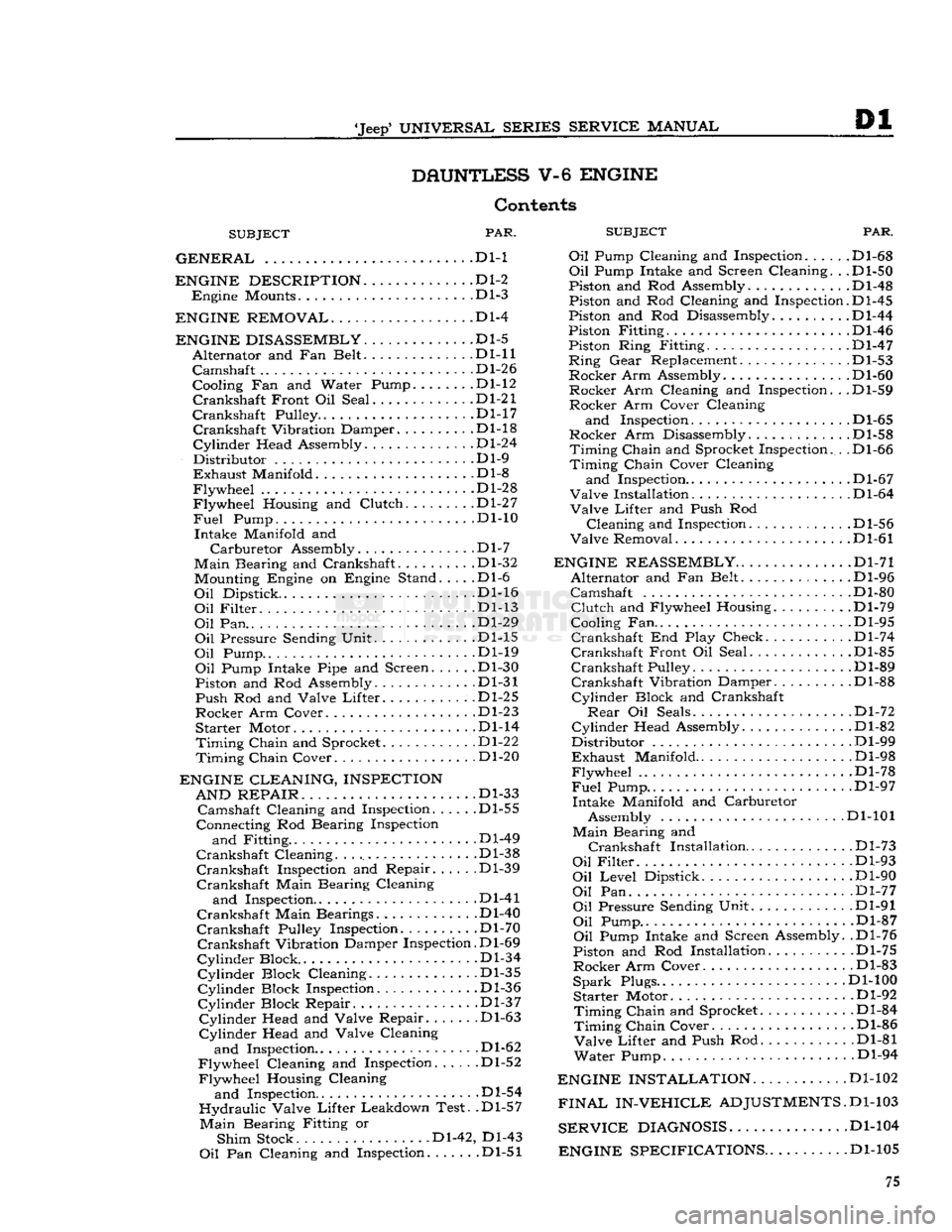
DAUNTLESS
V-6
ENGINE
Contents
SUBJECT
PAR.
SUBJEC
GENERAL
.... . . Dl-1 Oil Pump Cl(
ENGINE DESCRIPTION
D1-2
Engine
Mounts Dl-3
ENGINE REMOVAL
Dl-4
ENGINE DISASSEMBLY
Dl-5
Alternator
and Fan Belt Dl-11
Camshaft
.... Dl-26
Cooling Fan and Water Pump.
......
.Dl-12
Crankshaft
Front Oil Seal .Dl-21
Crankshaft
Pulley D1-17
Crankshaft
Vibration Damper Dl-18
Cylinder
Head Assembly Dl-24
Distributor
Dl-9
Exhaust
Manifold .Dl-8
Flywheel
Dl-28
Flywheel
Housing and
Clutch
Dl-27
Fuel
Pump. ... . .Dl-10
Intake
Manifold and
Carburetor
Assembly.
.............
.Dl-7
Main
Bearing and Crankshaft. Dl-32 Mounting Engine on Engine Stand. . . . .Dl-6
Oil
Dipstick. Dl-16
Oil
Filter
Dl-13
Oil
Pan.. ...
.......
.Dl-29
Oil
Pressure Sending Unit Dl-15
Oil
Pump Dl-19
Oil
Pump Intake Pipe and Screen Dl-30
Piston and Rod Assembly. Dl-31
Push
Rod and Valve
Lifter.
.Dl-25
Rocker
Arm Cover Dl-23
Starter
Motor Dl-14
Timing
Chain
and Sprocket Dl-22
Timing
Chain
Cover Dl-20
ENGINE CLEANING, INSPECTION AND REPAIR
. . ... .Dl-33
Camshaft
Cleaning and Inspection Dl-55
Connecting Rod Bearing Inspection
and
Fitting .Dl-49
Crankshaft
Cleaning Dl-38
Crankshaft
Inspection and Repair Dl-39
Crankshaft
Main Bearing Cleaning
and
Inspection Dl-41
Crankshaft
Main Bearings. Dl-40
Crankshaft
Pulley Inspection. Dl-70
Crankshaft
Vibration Damper Inspection. D1-69
Cylinder
Block .Dl-34
Cylinder
Block Cleaning Dl-35
Cylinder
Block Inspection Dl-36
Cylinder
Block Repair. .Dl-37
Cylinder
Head and Valve Repair .Dl-63
Cylinder
Head and Valve Cleaning
and
Inspection.. . .Dl-62
Flywheel
Cleaning and Inspection Dl-52
Flywheel
Housing Cleaning
and
Inspection Dl-54
Hydraulic
Valve
Lifter
Leakdown Test. .Dl-57
Main
Bearing Fitting or
Shim
Stock Dl-42, Dl-43
Oil
Pan Cleaning and Inspection .Dl-51
PAR.
and
Inspection. .... .Dl-68
Oil
Pump Intake and Screen Cleaning. . .Dl-50
Piston and Rod Assembly.
...........
.Dl-48
Piston and Rod Cleaning and Inspection.D1-45
Piston and Rod Disassembly Dl-44
Piston Fitting Dl-46
Piston Ring Fitting. .Dl-47
Ring
Gear
Replacement. .Dl-53
Rocker
Arm Assembly. Dl-60
Rocker
Arm Cleaning and Inspection. . .Dl-59
Rocker
Arm Cover Cleaning
and
Inspection D1-65
Rocker
Arm Disassembly .Dl-58
Timing
Chain
and Sprocket Inspection. . .Dl-66
Timing
Chain
Cover Cleaning
and
Inspection.. . Dl-67
Valve
Installation D1-64
Valve
Lifter
and Push Rod
Cleaning
and Inspection. . Dl-56
Valve
Removal Dl-61
ENGINE REASSEMBLY
Dl-71
Alternator
and Fan Belt Dl-96
Camshaft
Dl-80
Clutch
and Flywheel Housing Dl-79
Cooling Fan.. . .Dl-95
Crankshaft
End Play Check. . Dl-74
Crankshaft
Front Oil Seal Dl-85
Crankshaft
Pulley Dl-89
Crankshaft
Vibration Damper Dl-88
Cylinder
Block and Crankshaft
Rear
Oil Seals Dl-72
Cylinder
Head Assembly .Dl-82
Distributor
Dl-99
Exhaust
Manifold Dl-98
Flywheel
.Dl-78
Fuel
Pump.. .. . Dl-97
Intake
Manifold and Carburetor Assembly Dl-101
Main
Bearing and
Crankshaft
Installation
.
Dl-73
Oil
Filter
Dl-93
Oil
Level
Dipstick Dl-90
Oil
Pan Dl-77
Oil
Pressure Sending Unit Dl-91
Oil
Pump.. .Dl-87
Oil
Pump Intake and Screen Assembly. .Dl-76
Piston and Rod Installation Dl-75
Rocker
Arm Cover. Dl-83
Spark
Plugs.. Dl-100
Starter
Motor Dl-92
Timing
Chain
and Sprocket.
..........
.Dl-84
Timing
Chain
Cover Dl-86
Valve
Lifter
and Push Rod Dl-81
Water
Pump. Dl-94
ENGINE INSTALLATION
Dl-102
FINAL
IN-VEHICLE
ADJUSTMENTS.
D1-103
SERVICE
DIAGNOSIS
Dl-104
ENGINE SPECIFICATIONS
. .Dl-105 75
Page 77 of 376
'Jeep'
UNIVERSAL SERIES SERVICE
MANUAL
Dl
©©©©©©©©©
12697
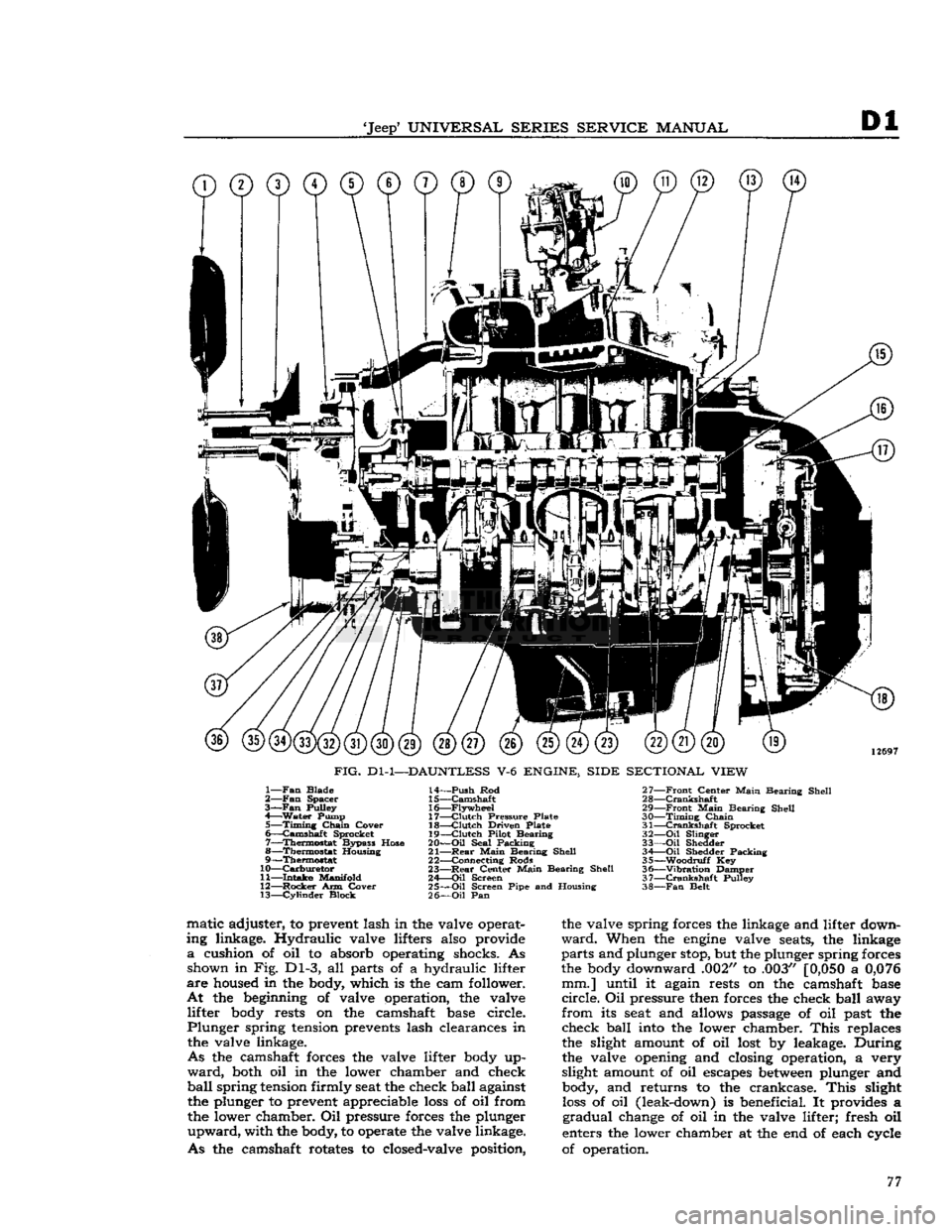
FIG.
Dl-1—DAUNTLESS
V-6
ENGINE, SIDE SECTIONAL VIEW
1—
Fan
Blade
2—
Fan
Spacer
3—Fan
Pulley
4—
Water
Pump 5—
Timing
Chain
Cover
6—
Camshaft
Sprocket
7—
Thermostat
Bypass Hose
8—
Thermostat
Housing
9—
Thermostat
10—
Carburetor
11—
Intake
Manifold
12—
Rocker
Arm Cover 13—
Cylinder
Block 14—
Push
Rod
15—
Camshaft
16—
Flywheel
17—
Clutch
Pressure Plate
18—
Clutch
Driven Plate
19—
Clutch
Pilot Bearing
20—
Oil
Seal Packing
21—
Rear
Main
Bearing Shell
22— Connecting Rods
23—
Rear
Center
Main
Bearing Shell
24—
Oil
Screen
25—
Oil
Screen Pipe and Housing
26—
Oil
Pan 27—
Front
Center
Main
Bearing Shell
28—
Crankshaft
29—
Front
Main
Bearing Shell
30—
Timing
Chain
31—
Crankshaft
Sprocket
32—
Oil
Slinger
33—
Oil
Shedder 34 Oil Shedder Packing
35—
-Woodruff
Key
36—
"Vibration
Damper
37—
Crankshaft
Pulley
38—
Fan
Belt matic adjuster, to prevent lash in the valve operat
ing linkage. Hydraulic valve lifters also provide
a
cushion of oil to absorb operating shocks. As shown in Fig. Dl-3, all parts of a hydraulic lifter
are
housed in the body, which is the cam follower.
At
the beginning of valve operation, the valve lifter body rests on the camshaft base circle.
Plunger
spring tension prevents lash clearances in the valve linkage.
As
the camshaft forces the valve lifter body up
ward,
both oil in the lower chamber and check
ball
spring
tension firmly seat the check ball against the plunger to prevent appreciable
loss
of oil from
the lower chamber. Oil pressure forces the plunger
upward,
with the body, to operate the valve linkage.
As
the camshaft rotates to closed-valve position, the valve spring forces the linkage and lifter down
ward.
When the
engine
valve seats, the linkage
parts
and plunger stop, but the plunger spring forces
the body downward .002" to .003"
[0,050
a
0,076
mm.] until it again rests on the camshaft base
circle.
Oil pressure then forces the check ball away
from
its seat and allows passage of oil past the check ball into the lower chamber.
This
replaces
the slight amount of oil lost by leakage. During
the valve opening and closing operation, a very
slight amount of oil escapes
between
plunger and body, and returns to the crankcase.
This
slight
loss
of oil (leak-down) is beneficial. It provides a
gradual
change of oil in the valve lifter; fresh oil
enters the lower chamber at the end of each cycle
of operation. 77
Page 79 of 376
'Jeep*
UNIVERSAL SERIES SERVICE
MANUAL
Dl
12710
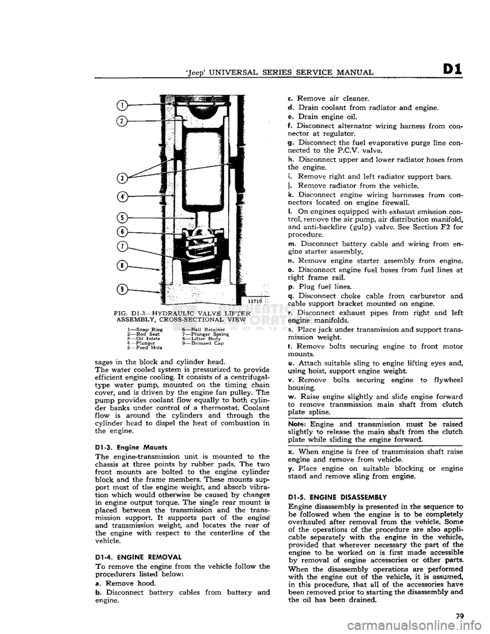
FIG.
D1
-3—HYDRAULIC VALVE
LIFTER
ASSEMBLY, CROSS-SECTIONAL VIEW
1—
Snap
Ring
6—Ball Retainer
2— Rod
Seat
7—Plunger Spring
3—
Oil
Inlets
8—Lifter
Body
4—
Plunger
9—Bronzed
Cap
5— Feed
Hole
sages
in the block and cylinder head.
The
water cooled system is pressurized to provide efficient
engine
cooling. It consists of a centrifugal-
type water pump, mounted on the timing chain cover, and is driven by the
engine
fan pulley. The
pump provides coolant flow equally to both
cylin
der banks under control of a thermostat. Coolant
flow is around the cylinders and through the
cylinder
head to dispel the heat of combustion in
the engine.
Dl-3.
Engine Mounts
The
engine-transmission unit is mounted to the chassis at three points by rubber pads. The two
front mounts are bolted to the
engine
cylinder
block and the frame members. These mounts sup port most of the
engine
weight, and absorb
vibra
tion which would otherwise be caused by changes
in
engine
output torque. The single
rear
mount is
placed
between
the transmission and the trans mission support. It supports part of the engine'
and
transmission weight, and locates the
rear
of
the
engine
with respect to the centerline of the
vehicle.
Dl-4. ENGINE REMOVAL
To
remove the
engine
from the vehicle follow the
procedurers listed below:
a.
Remove hood. b. Disconnect battery cables from battery and
engine. c. Remove air cleaner.
d.
Drain
coolant from radiator and engine.
e.
Drain
engine
oil.
f. Disconnect alternator wiring harness from con nector at regulator.
cj.
Disconnect the fuel evaporative purge line con nected to the
P.C.V.
valve.
h.
Disconnect upper and lower radiator
hoses
from
the engine.
i.
Remove right and left radiator support
bars,
j.
Remove radiator from the vehicle.
k.
Disconnect
engine
wiring harnesses from con
nectors located on
engine
firewall.
I.
On
engines
equipped with exhaust emission con
trol,
remove the air pump, air distribution manifold,
and
anti-backfire (gulp) valve. See Section F2 for
procedure.
m.
Disconnect battery cable and wiring from en
gine
starter assembly.
n.
Remove
engine
starter assembly from engine,
o.
Disconnect
engine
fuel
hoses
from fuel lines at
right
frame
rail,
p. Plug fuel lines.
q.
Disconnect choke cable from carburetor and cable support bracket mounted on engine,
r.
Disconnect exhaust pipes from right and left
engine
manifolds.
s. Place
jack
under transmission and support trans
mission weight.
f. Remove
bolts
securing
engine
to front motor mounts.
u.
Attach suitable sling to
engine
lifting
eyes
and,
using hoist, support
engine
weight.
v. Remove
bolts
securing
engine
to flywheel housing.
w. Raise
engine
slightly and slide
engine
forward
to remove transmission main shaft from clutch plate spline.
Note:
Engine and transmission must be raised
slightly to release the main shaft from the clutch
plate while sliding the
engine
forward.
x. When
engine
is free of transmission shaft raise
engine
and remove from vehicle,
y. Place
engine
on suitable blocking or
engine
stand and remove sling from engine.
Dl-5.
ENGINE DISASSEMBLY
Engine
disassembly is presented in the sequence to be followed when the
engine
is to be completely
overhauled after removal from the vehicle. Some of the operations of the procedure are also applicable separately with the
engine
in the vehicle,
provided that wherever necessary the part of the
engine
to be worked on is first made accessible by removal of
engine
accessories or other parts.
When
the disassembly operations are performed
with
the
engine
out of the vehicle, it is assumed,
in
this procedure, that all of the accessories have
been removed
prior
to starting the disassembly and
the oil has been drained.
Page 80 of 376
Dl
DAUNTLESS
V-6
ENGINE
In
addition to the instructions covering operations
for disassembling the
engine
out of the vehicle, special instructions are given to cover different
operations required when disassembly is
done
with
the
engine
installed.
During
disassembly operations, the
engine
should be mounted in a suitable
engine
repair stand.
Where
practicable, modify or adapt an existing re
pair
stand as necessary to accommodate the
engine.
If
an
engine
repair stand is not used, take care to
perform
disassembly operations in a manner that
will
protect personnel against an accident and the
engine
and its parts against damage.
Dl-6.
Mounting Engine
On
Engine Stand
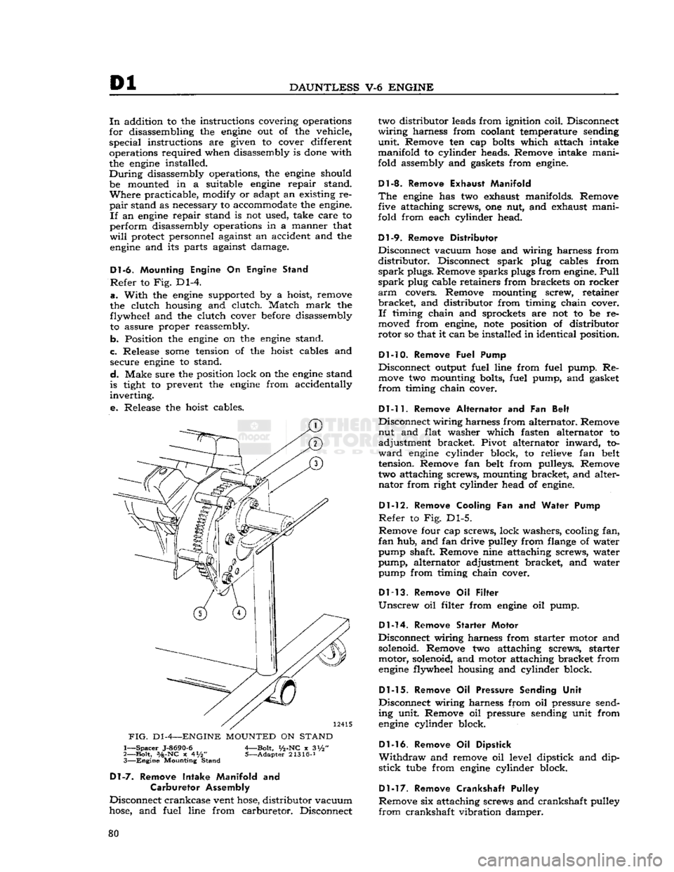
Refer
to Fig. Dl-4.
a.
With
the
engine
supported by a hoist, remove
the clutch housing and clutch. Match
mark
the flywheel and the clutch cover before disassembly to assure proper reassembly.
b. Position the
engine
on the
engine
stand.
c. Release
some
tension of the hoist cables and secure
engine
to stand.
d.
Make sure the position lock on the
engine
stand
is tight to prevent the
engine
from accidentally
inverting.
e.
Release the hoist cables.
FIG.
D1
-4—ENGINE
MOUNTED
ON
STAND
1—
Spacer
J-8690-6
A—Bolt,
i/2-NC
x 3i/2"
2—
Bolt,
3/a-NC
x 4*/2" 5—Adapter 21316-J 3—
Engine
Mounting Stand
Dl-7.
Remove Intake Manifold
and
Carburetor Assembly
Disconnect crankcase vent
hose,
distributor vacuum
hose,
and fuel line from carburetor. Disconnect two distributor leads from ignition coil. Disconnect
wiring
harness from coolant temperature sending
unit.
Remove ten cap
bolts
which attach intake
manifold to cylinder heads. Remove intake mani
fold assembly and gaskets from
engine.
Dl-8. Remove Exhaust Manifold
The
engine
has two exhaust manifolds. Remove five attaching screws, one nut, and exhaust mani
fold from each cylinder head.
Dl-9.
Remove Distributor
Disconnect vacuum
hose
and wiring harness from
distributor.
Disconnect spark plug cables from
spark
plugs. Remove sparks plugs from
engine.
Pull
spark
plug cable retainers from brackets on rocker
arm
covers. Remove mounting screw, retainer
bracket,
and distributor from timing chain cover.
If
timing chain and sprockets are not to be re
moved from
engine,
note
position of distributor
rotor so that it can be installed in identical position.
Dl-10. Remove
Fuel Pump
Disconnect output fuel line from fuel pump. Re
move
two mounting bolts, fuel pump, and gasket
from
timing chain cover.
Dl-11.
Remove Alternator
and Fan
Belt
Disconnect wiring harness from alternator. Remove nut and flat washer which fasten alternator to
adjustment bracket. Pivot alternator
inward,
to
ward
engine
cylinder block, to relieve fan belt
tension. Remove fan belt from pulleys. Remove
two attaching screws, mounting bracket, and alter nator from right cylinder head of
engine.
Dl-12.
Remove Cooling
Fan and
Water Pump
Refer
to Fig. Dl-5.
Remove four cap screws, lock washers, cooling fan,
fan
hub, and fan drive pulley from flange of water
pump shaft. Remove nine attaching screws, water
pump, alternator adjustment bracket, and water pump from timing chain cover.
Dl-13.
Remove
Oil
Filter
Unscrew
oil filter from
engine
oil pump.
Dl-14.
Remove Starter Motor
Disconnect wiring harness from starter motor and
solenoid. Remove two attaching screws, starter motor, solenoid, and motor attaching bracket from
engine
flywheel housing and cylinder block.
Dl-15.
Remove
Oil
Pressure Sending Unit
Disconnect wiring harness from oil pressure send
ing unit. Remove oil pressure sending unit from
engine
cylinder block.
Dl-16.
Remove
Oil
Dipstick
Withdraw
and remove oil level dipstick and dip
stick
tube
from
engine
cylinder block.
Dl-17.
Remove Crankshaft Pulley
Remove six attaching screws and crankshaft pulley
from
crankshaft vibration damper. 80
Page 82 of 376
Dl
DAUNTLESS
V-6
ENGINE
d.
Use two large screwdrivers to alternately pry
forward the camshaft sprocket and
then
the crank
shaft sprocket, until the camshaft sprocket is pried
from the camshaft. Remove the camshaft sprocket, sprocket key, and timing chain from the
engine;
then
pry the crankshaft sprocket from the crankshaft.
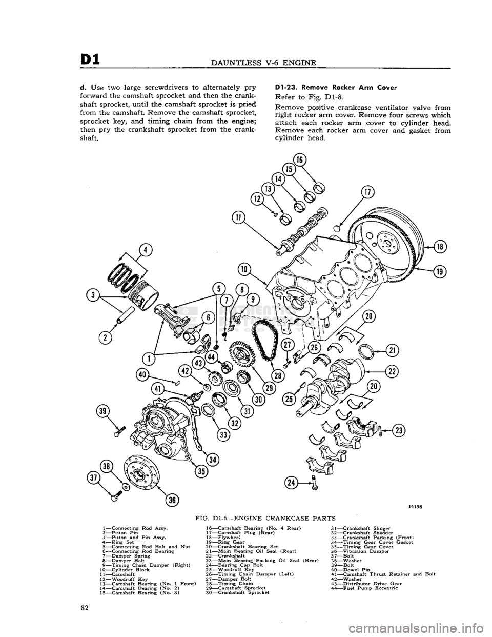
Dl-23.
Remove Rocker Arm Cover
Refer to Fig. Dl-8.
Remove
positive
crankcase ventilator valve from right rocker arm cover. Remove four screws which attach each rocker arm cover to cylinder head.
Remove each rocker arm cover and
gasket
from cylinder head. 14198
FIG.
Dl-6—ENGINE
CRANKCASE
PARTS
1— Connecting Rod Assy.
2— —Piston Pin
3—
Piston and Pin Assy.
4—
Ring
Set 5— Connecting Rod
Bolt
and Nut
6— Connecting Rod Bearing
7— Damper Spring
8— Damper
Bolt
9—
Timing
Chain Damper (Right)
10—
Cylinder
Block
11— Camshaft
12—
Woodruff
Key
13— Camshaft Bearing (No. 1 Front) 14— Camshaft Bearing (No. 2)
15— Camshaft Bearing (No. 3) 16—
Camshaft
Bearing (No. 4
Rear)
31-
17—
Camshaft
Plug
(Rear)
32-18—
Flywheel
33-
19—
Ring
Gear
34-
20— Crankshaft Bearing Set 35-
21—
Main
Bearing Oil Seal
(Rear)
36-
2 2—Crankshaft 3 7-
23—
Main
Bearing Packing Oil Seal
(Rear)
28-
24— Bearing Cap
Bolt
39-
25— Woodruff Key 40-
26—
Timing
Chain Damper
(Left)
41-
27— Damper Bolt 42- 28—
Timing
Chain
43-
29—
Camshaft
Sprocket 44-
30— Crankshaft Sprocket
—Crankshaft
Slinger
—Crankshaft
Shedder
—Crankshaft
Packing (Front)
—Timing
Gear
Cover Gasket
—Timing
Gear
Cover
—Vibration
Damper
-Bolt
-Washer
-Bolt
—Dowel Pin
-Camshaft
Thrust
Retainer and Bolt
—Washer
-Distributor
Drive
Gear
—Fuel
Pump Eccentric
82
Page 83 of 376
'Jeep'
UNIVERSAL
SERIES SERVICE
MANUAL
Dl
14028
j
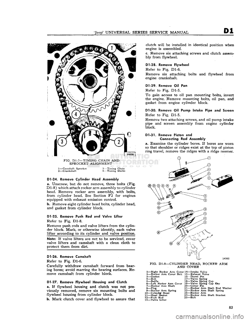
FIG.
D1-7—TIMING
CHAIN
AND
SPROCKET ALIGNMENT 1—
Camshaft Sprocket
2—
Crankshaft
3—Timing
Chain
Timing
Marks
Dl-24.
Remove
Cylinder
Head Assembly
a.
Unscrew, but do not remove, three
bolts
(Fig.
Dl-8)
which attach rocker
arm
assembly to cylinder
head.
Remove rocker arm assembly, with bolts,
from
cylinder head. See Section F2 for
engines
equipped with exhaust emission control.
b. Remove
eight
cylinder head bolts, cylinder head,
and
gasket from cylinder block.
Dl-25.
Remove Push Rod and Valve
Lifter
Refer
to Fig. Dl-8. Remove push rods and valve lifters from the
cylin
der
block.
Mark,
or otherwise identify, each valve
lifter
according to its cylinder and valve position.
Note:
If valve lifters are not to be serviced, cover
valve lifters and camshaft with a clean cloth to
protect them from dirt
Dl-26.
Remove Camshaft
Refer
to Fig. Dl-6.
Carefully
withdraw camshaft forward from bear
ing bores; avoid marring the bearing surfaces. Re
move
camshaft from cylinder block.
Dl-27.
Remove Flywheel Housing and
Clutch
a.
If flywheel housing and clutch was not pre
viously removed, remove six mounting
bolts
and
flywheel housing from cylinder block.
b.
Mark
clutch cover and flywheel to assure that
clutch
will
be installed in identical position when
engine
is assembled.
c. Remove six attaching screws and clutch assem
bly from flywheel.
D1-28. Remove Flywheel
Refer
to Fig. Dl-6.
Remove six attaching
bolts
and flywheel from
engine
crankshaft.
Dl-29.
Remove Oil Pan
Refer
to Fig. Dl-5.
To
gain access to oil pan mounting bolts, invert
the
engine.
Remove mounting bolts, oil pan, and gasket from
engine
cylinder block.
Dl-30.
Remove Oil Pump Intake Pipe and Screen
Refer
to Fig. Dl-5.
Remove two attaching screws, and oil pump intake
pipe and screen assembly from
engine
cylinder block.
Dl-31.
Remove Piston and
Connecting
Rod Assembly
a.
Examine the cylinder bores. If bores are worn
so that shoulder or ridges exist at the top of piston
ring
travel, remove the ridges with a ridge reamer.
FIG.
Dl-8-
-CYLINDER HEAD,
AND COVER
ROCKER
ARM
1—
—Right
Rocker
Arm
Cover
2—
Rocker
Arm
Cover
Bolt
3—
Gasket
4—
Bolt
5—
Baffle
6—
Left
Rocker
Arm
Cover
7—
Rocker
Arm Shaft
8—Plug
9—
Rocker
Arm Spring
10—
Cylinder
Head
11—
Head
Gasket
12—
Push
Rod
13—
Valve
Lifter
14—
Intake
Valve
15—
Exhaust
Valve
16—
Dowel
Pin
17—
Valve
Spring 18—
Valve
Spring Cap
19—
Valve
Spring Cap Key
20—
Cotter
Pin
21—
Rocker
Arm Shaft End Washer
22—
Rocker
Arm Shaft Spring
23—
Rocker
Arm
24—
Rocker
Arm Shaft
Bracket
25—
Bolt
83