ECO mode JEEP GLADIATOR 2023 User Guide
[x] Cancel search | Manufacturer: JEEP, Model Year: 2023, Model line: GLADIATOR, Model: JEEP GLADIATOR 2023Pages: 448, PDF Size: 17.37 MB
Page 64 of 448
62GETTING TO KNOW YOUR VEHICLE
AUTOMATIC CLIMATE CONTROL
D
ESCRIPTIONS AND FUNCTIONS
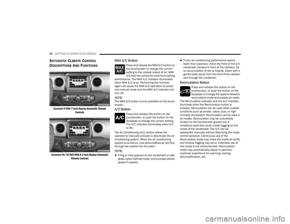
Uconnect 4 With 7-inch Display Automatic Climate
Controls
Uconnect 4C/4C NAV With 8.4-inch Display Automatic Climate Controls
MAX A/C Button
Press and release the MAX A/C button on
the touchscreen to change the current
setting to the coldest output of air. MAX
A/C sets the control for maximum cooling
performance. The MAX A/C indicator illuminates
when MAX A/C is on. Performing this function
again will cause the MAX A/C operation to switch
into manual mode and the MAX A/C indicator will
turn off.
NOTE:The MAX A/C button is only available on the touch -
screen.
A/C Button
Press and release this button on the
touchscreen, or push the button on the
faceplate to change the current setting.
The A/C indicator illuminates when A/C
is ON.
The Air Conditioning (A/C) button allows the
operator to manually activate or deactivate the air
conditioning system. When the air conditioning
system is turned on, cool dehumidified air will flow
through the outlets into the cabin.
NOTE:
If fog or mist appears on the windshield or side
glass, select Defrost mode, and increase blower
speed if needed.
If your air conditioning performance seems
lower than expected, check the front of the A/C
condenser (located in front of the radiator), for
an accumulation of dirt or insects. Clean with a
gentle water spray from the front of the radiator
and through the condenser.
Recirculation Button
Press and release this button on the
touchscreen, or push the button on the
faceplate to change the system between
recirculation mode and outside air mode.
The Recirculation indicator and the A/C indicator
illuminate when the Recirculation button is
pressed. Recirculation can be used when outside
conditions such as smoke, odors, dust, or high
humidity are present. Recirculation can be used in
all modes. Recirculation may be unavailable
(button on the touchscreen grayed out) if
conditions exist that could create fogging on the
inside of the windshield. The A/C can be
deselected manually without disturbing the mode
control selection. Continuous use of the
Recirculation mode may make the inside air stuffy
and window fogging may occur. Extended use of
this mode is not recommended. Recirculation
mode may automatically adjust to optimize
customer experience for warming, cooling,
dehumidification, etc.
23_JT_OM_EN_USC_t.book Page 62
Page 65 of 448
GETTING TO KNOW YOUR VEHICLE63
AUTO Button
Press and release this button on the
touchscreen, or push the button on the
faceplate, to change the current setting.
The AUTO indicator illuminates when
AUTO is on. This feature automatically controls the
interior cabin temperature by adjusting distribution
and blower speed. Air conditioning (A/C) may be
active during AUTO operation to improve
performance. AUTO Mode is highly recommended
for efficiency. Toggling this function will cause the
system to switch between manual mode and
automatic mode Ú page 67.
Front Defrost
Turn the Mode control knob to Front
Defrost to change the current airflow
setting to Defrost mode. The Front
Defrost indicator illuminates when Front
Defrost is on. Air comes from the windshield and
side window demist outlets. When the defrost
button is selected, the blower level may increase.
Use Defrost mode with maximum temperature
settings for best windshield and side window
defrosting and defogging. When toggling the front
defrost mode button, the Climate Control system
will return to the previous setting.
Rear Defrost Button
Press and release the Rear Defrost
Control button on the touchscreen, or
push and release the button on the
faceplate to turn on the rear window
defroster and the heated outside mirrors (if
equipped). The Rear Defrost indicator illuminates
when the rear window defroster is on. The rear
window defroster automatically turns off after
10 minutes.
Driver And Passenger Temperature Up And
Down Buttons
These buttons provide the driver and passenger
with independent temperature control.
Push the red button on the faceplate or
touchscreen or press and slide the
temperature bar towards the red arrow
button on the touchscreen for warmer
temperature settings.
Push the blue button on the faceplate or
touchscreen or press and slide the
temperature bar towards the blue arrow
button on the touchscreen for cooler
temperature settings.
SYNC Button
Press the SYNC button on the
touchscreen to toggle the Sync feature
on/off. The SYNC indicator illuminates
when SYNC is on. SYNC is used to
synchronize the passenger temperature setting
with the driver temperature setting. Changing the
passenger temperature setting while in SYNC will
automatically exit this feature.
NOTE:The SYNC button is only available on the touch-
screen.
CAUTION!
Failure to follow these cautions can cause
damage to the heating elements:
Use care when washing the inside of the rear
window. Do not use abrasive window cleaners
on the interior surface of the window. Use a
soft cloth and a mild washing solution, wiping
parallel to the heating elements. Labels can
be peeled off after soaking with warm water.
Do not use scrapers, sharp instruments, or
abrasive window cleaners on the interior
surface of the window.
Keep all objects a safe distance from the
window.
2
23_JT_OM_EN_USC_t.book Page 63
Page 67 of 448
GETTING TO KNOW YOUR VEHICLE65
MAX A/C Setting
Set the temperature control knob to the
MAX A/C setting to change the current
setting to the coldest output of air.
Moving the temperature control knob
away from the MAX A/C setting causes the MAX
A/C operation to exit.
A/C Button
Push the A/C button to engage the Air
Conditioning (A/C). The A/C indicator
illuminates when A/C is on.
NOTE:
For Manual Climate Controls, if the system is in
Mix, Floor or Defrost Mode, the A/C can be
turned off, but the A/C system shall remain
active to prevent fogging of the windows.
If fog or mist appears on the windshield or side
glass, select Defrost mode, and increase blower
speed if needed.
If your air conditioning performance seems
lower than expected, check the front of the A/C
condenser (located in front of the radiator), for
an accumulation of dirt or insects. Clean with a
gentle water spray from the front of the radiator
and through the condenser.
Recirculation Button
Push the Recirculation button on the
faceplate to change the system between
recirculation mode and outside air mode.
The Recirculation indicator and the A/C
indicator (if equipped) illuminate when the
Recirculation button is pressed. Recirculation can
be used when outside conditions such as smoke,
odors, dust, or high humidity are present.
Recirculation can be used in all modes except for
Defrost. Recirculation may be unavailable if
conditions exist that could create fogging on the
inside of the windshield. The A/C can be deselected
manually without disturbing the mode control
selection. Continuous use of the Recirculation
mode may make the inside air stuffy and window
fogging may occur. Extended use of this mode is
not recommended. On systems with Manual
Climate Controls, the Recirculation mode is not
allowed in Defrost mode to improve window
clearing operation. Recirculation is disabled
automatically if this mode is selected. Attempting
to use Recirculation while in this mode causes the
LED on the control button to blink and then turn off.
Front Defrost
Turn the Mode control knob to Front
Defrost to change the current airflow
setting to Defrost mode. The Front
Defrost indicator illuminates when Front
Defrost is on. Air comes from the windshield and
side window demist outlets. When the defrost
button is selected, the blower level may increase.
Use Defrost mode with maximum temperature
settings for best windshield and side window
defrosting and defogging. When toggling the front
defrost mode button, the Climate Control system
will return to the previous setting.
Rear Defrost Button
Push and release the Rear Defrost
Control button to turn on the rear window
defroster and the heated outside mirrors
(if equipped). The Rear Defrost indicator
illuminates when the rear window defroster is on.
The rear window defroster automatically turns off
after 10 minutes.
2
23_JT_OM_EN_USC_t.book Page 65
Page 69 of 448
GETTING TO KNOW YOUR VEHICLE67
AUTOMATIC TEMPERATURE CONTROL
(ATC) — I
F EQUIPPED
Automatic Operation
1. Push the AUTO button on the faceplate, or the
AUTO button on the touchscreen on the
Automatic Temperature Control (ATC) Panel.
2. Next, adjust the temperature that you would like the system to maintain by adjusting the
driver and passenger temperature control
buttons. Once the desired temperature is
displayed, the system will achieve and
automatically maintain that comfort level.
3. When the system is set up for your comfort level, it is not necessary to change the
settings. You will experience the greatest
efficiency by simply allowing the system to
function automatically.
NOTE:
It is not necessary to move the temperature
settings for cold or hot vehicles. The system
automatically adjusts the temperature, mode,
and blower speed to provide comfort as quickly
as possible.
The temperature can be displayed in U.S. or
Metric units by selecting the U.S./Metric
customer-programmable feature within
Uconnect Settings Ú page 215. To provide you with maximum comfort in the
Automatic mode during cold start-ups, the blower
fan will remain on low until the engine warms up.
The blower will increase in speed and transition
into Auto mode.
Manual Operation Override
This system offers a full complement of manual
override features. The AUTO symbol in the front
ATC display will be turned off when the system is
being used in the manual mode.
CLIMATE VOICE COMMANDS
Adjust vehicle temperatures hands-free and keep
everyone comfortable while you keep moving
ahead.
Push the VR button on the steering wheel. After the
beep, say one of the following commands:
“
Set the driver temperature to 70 degrees ”
“Set the passenger temperature to 70 degrees ”
Did You Know:
Voice Command for Climate may
only be used to adjust the interior temperature of
your vehicle. Voice Command will not work to adjust
the heated seats or steering wheel if equipped.
OPERATING TIPS
NOTE:Refer to the chart at the end of this section for
suggested control settings for various weather
conditions.
Summer Operation
The engine cooling system must be protected with
a high-quality antifreeze coolant to provide proper
corrosion protection and to protect against engine
overheating. OAT coolant (conforming to
MS.90032) is recommended.
Winter Operation
To ensure the best possible heater and defroster
performance, make sure the engine cooling
system is functioning properly and the proper
amount, type, and concentration of coolant is
used. Use of the Air Recirculation mode during
Winter months is not recommended, because it
may cause window fogging.
Vacation/Storage
For information on maintaining the Climate Control
system when the vehicle is being stored for an
extended period of time, see Ú page 411.
2
23_JT_OM_EN_USC_t.book Page 67
Page 77 of 448
GETTING TO KNOW YOUR VEHICLE75
Phone & Bluetooth® Pairing
A feature of the Jeep® wireless speaker is the
ability for the Jeep® wireless speaker to connect to
devices using Bluetooth®. Follow these simple
steps to connect a Bluetooth®-enabled device to
the Jeep® wireless speaker:
1. Press and hold the power button for 2-3 sec-
onds to turn the Jeep® wireless speaker on.
2. Turn “on” Bluetooth® for the device you desire to be connected to the Jeep® wireless
speaker. For instructions on how to turn on
and off Bluetooth® settings for the desired
device, refer to the device’s user manual.
3. When powered on, the Jeep® wireless speaker will automatically enter pairing mode.
To pair a second device, press and hold the
Bluetooth® button for 2-3 seconds, until an
audio cue is heard. Then go to the devices’
Bluetooth® settings and select “Jeep®
Speaker” from the list.
The Jeep® wireless speaker will remember the last
eight devices it has paired with.
NOTE:If the Jeep® wireless speaker is left on with an
inactive Bluetooth® connection for 30 minutes, it
will automatically turn off. The Jeep® wireless
speaker can be turned on again by pressing and
holding the power button for 2-3 seconds.
Resetting Your Jeep® Wireless Speaker
To reset the Jeep® wireless speaker to its original
factory setting, press and hold the reset button
under the back cover for 8-10 seconds.
Speakerphone
The speakerphone feature can be used by
pressing the “Voice Control” button on the Jeep®
wireless speaker. This feature can be used to
answer and end calls over the speakerphone.
Volume And Playback Control
Volume can be increased or decreased by briefly
pressing the + button or - button. When the
maximum volume is reached, an audio cue will
sound.
To skip to the next track, press and hold the
+ button. To go to the previous track, press the
- button.
Qualcomm TrueWireless™ Stereo
A feature of the Jeep® wireless speaker is being
able to pair two Jeep® wireless speakers together
for Qualcomm TrueWireless™ Stereo. This feature
allows for two Jeep® wireless speakers to play left
and right stereo sound. Below are the steps needed for Qualcomm
TrueWireless™ Stereo:
1. Push and hold the power button on both
Jeep® wireless speakers until both speakers
turn on.
2. Place both speakers into Qualcomm TrueWireless™ Stereo pairing mode. This can
be achieved by pressing and holding the
Battery Status button on both speakers until
an audio notification is heard from both
speakers.
3. Connect one of the Jeep® wireless speakers to the Bluetooth® source. Refer to previous
section “Phone & Bluetooth® Pairing” for
additional information.
4. Once the Jeep® wireless speaker is connected to the Bluetooth® device, audio will be played
from both speakers.
NOTE:While in Qualcomm TrueWireless™ Stereo mode,
the volume will not have independent speaker
control. Pushing the Up or Down Volume button on
either Jeep® wireless speaker will affect the audio
output on both, as well as volume adjustments on
the Bluetooth® device.
2
23_JT_OM_EN_USC_t.book Page 75
Page 117 of 448
GETTING TO KNOW YOUR VEHICLE115
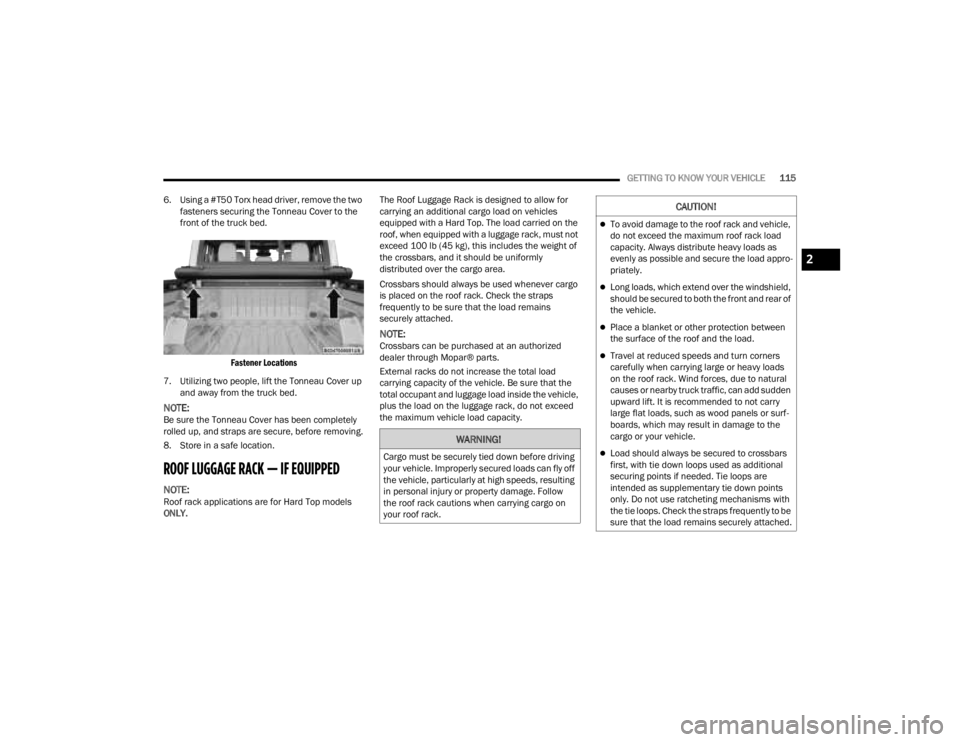
6. Using a #T50 Torx head driver, remove the two fasteners securing the Tonneau Cover to the
front of the truck bed.
Fastener Locations
7. Utilizing two people, lift the Tonneau Cover up and away from the truck bed.
NOTE:Be sure the Tonneau Cover has been completely
rolled up, and straps are secure, before removing.
8. Store in a safe location.
ROOF LUGGAGE RACK — IF EQUIPPED
NOTE:Roof rack applications are for Hard Top models
ONLY. The Roof Luggage Rack is designed to allow for
carrying an additional cargo load on vehicles
equipped with a Hard Top. The load carried on the
roof, when equipped with a luggage rack, must not
exceed 100 lb (45 kg), this includes the weight of
the crossbars, and it should be uniformly
distributed over the cargo area.
Crossbars should always be used whenever cargo
is placed on the roof rack. Check the straps
frequently to be sure that the load remains
securely attached.
NOTE:Crossbars can be purchased at an authorized
dealer through Mopar® parts.
External racks do not increase the total load
carrying capacity of the vehicle. Be sure that the
total occupant and luggage load inside the vehicle,
plus the load on the luggage rack, do not exceed
the maximum vehicle load capacity.
WARNING!
Cargo must be securely tied down before driving
your vehicle. Improperly secured loads can fly off
the vehicle, particularly at high speeds, resulting
in personal injury or property damage. Follow
the roof rack cautions when carrying cargo on
your roof rack.
CAUTION!
To avoid damage to the roof rack and vehicle,
do not exceed the maximum roof rack load
capacity. Always distribute heavy loads as
evenly as possible and secure the load appro
-
priately.
Long loads, which extend over the windshield,
should be secured to both the front and rear of
the vehicle.
Place a blanket or other protection between
the surface of the roof and the load.
Travel at reduced speeds and turn corners
carefully when carrying large or heavy loads
on the roof rack. Wind forces, due to natural
causes or nearby truck traffic, can add sudden
upward lift. It is recommended to not carry
large flat loads, such as wood panels or surf -
boards, which may result in damage to the
cargo or your vehicle.
Load should always be secured to crossbars
first, with tie down loops used as additional
securing points if needed. Tie loops are
intended as supplementary tie down points
only. Do not use ratcheting mechanisms with
the tie loops. Check the straps frequently to be
sure that the load remains securely attached.
2
23_JT_OM_EN_USC_t.book Page 115
Page 123 of 448
GETTING TO KNOW YOUR INSTRUMENT PANEL121
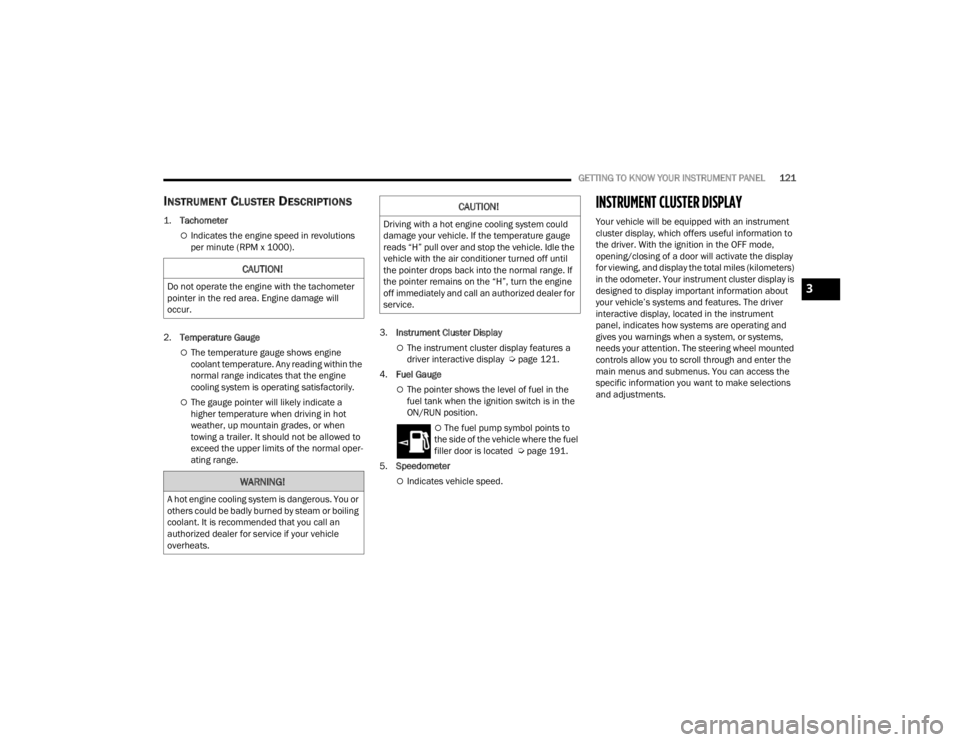
INSTRUMENT CLUSTER DESCRIPTIONS
1.
Tachometer
Indicates the engine speed in revolutions
per minute (RPM x 1000).
2. Temperature Gauge
The temperature gauge shows engine
coolant temperature. Any reading within the
normal range indicates that the engine
cooling system is operating satisfactorily.
The gauge pointer will likely indicate a
higher temperature when driving in hot
weather, up mountain grades, or when
towing a trailer. It should not be allowed to
exceed the upper limits of the normal oper -
ating range. 3.
Instrument Cluster Display
The instrument cluster display features a
driver interactive display Ú page 121.
4. Fuel Gauge
The pointer shows the level of fuel in the
fuel tank when the ignition switch is in the
ON/RUN position.
The fuel pump symbol points to
the side of the vehicle where the fuel
filler door is located Ú page 191.
5. Speedometer
Indicates vehicle speed.
INSTRUMENT CLUSTER DISPLAY
Your vehicle will be equipped with an instrument
cluster display, which offers useful information to
the driver. With the ignition in the OFF mode,
opening/closing of a door will activate the display
for viewing, and display the total miles (kilometers)
in the odometer. Your instrument cluster display is
designed to display important information about
your vehicle’s systems and features. The driver
interactive display, located in the instrument
panel, indicates how systems are operating and
gives you warnings when a system, or systems,
needs your attention. The steering wheel mounted
controls allow you to scroll through and enter the
main menus and submenus. You can access the
specific information you want to make selections
and adjustments.
CAUTION!
Do not operate the engine with the tachometer
pointer in the red area. Engine damage will
occur.
WARNING!
A hot engine cooling system is dangerous. You or
others could be badly burned by steam or boiling
coolant. It is recommended that you call an
authorized dealer for service if your vehicle
overheats.
CAUTION!
Driving with a hot engine cooling system could
damage your vehicle. If the temperature gauge
reads “H” pull over and stop the vehicle. Idle the
vehicle with the air conditioner turned off until
the pointer drops back into the normal range. If
the pointer remains on the “H”, turn the engine
off immediately and call an authorized dealer for
service.
3
23_JT_OM_EN_USC_t.book Page 121
Page 125 of 448
GETTING TO KNOW YOUR INSTRUMENT PANEL123
and release the OK button. To reset the oil change
indicator system (after performing the scheduled
maintenance), refer to the following procedure.
Oil Life Reset
1. Without pushing the brake pedal, place the ignition in the ON/RUN mode (do not start the
engine).
2. Navigate to "Oil Life" submenu in "Vehicle Info" in the instrument cluster display.
3. Push and hold the OK button until the gauge
resets to 100%.
Secondary Method For Oil Change Reset
Procedure
1. Without pushing the brake pedal, place the ignition in the ON/RUN position (do not start
the engine).
2. Fully press the accelerator pedal, slowly, three times within ten seconds.
3. Without pushing the brake pedal, place the ignition in the OFF position.
NOTE:If the indicator message illuminates when you start
the vehicle, the oil change indicator system did not
reset. If necessary, repeat this procedure.
OFF ROAD+ DISPLAY — IF EQUIPPED
When the Off Road+ button is pushed in the switch
bank, the Instrument Cluster Display will begin to
show messages related to the feature. Depending
on the Four Wheel Drive mode in use, the
messages will differ, and after five seconds, all
messages will clear from the display. The
messages are as follows:
2H: Off Road+ Unavailable, Shift to 4WD
4H: 4WD High Off Road+ Active
4L: 4WD Low Off Road+ Active
Adaptive Cruise Control (ACC) and Cruise Control
are not available when using Off Road+. If either
option is selected, a dedicated message will
display indicating that the features are not usable
concurrently. Messages are as follows:
4H: Cruise Control — Cruise Control Unavailable
in Off Road+
4H: Adaptive Cruise Control — Adaptive Cruise
Control (ACC) Unavailable in Off Road+
4L: Cruise Control — Cruise Control Unavailable
in 4WD Low
4L: Adaptive Cruise Control — Adaptive Cruise
Control (ACC) Unavailable in 4WD Low
NOTE:The behavior of Electronic Stability Control while in
Off Road+ varies depending on the 4WD status. If
the vehicle is in 4WD High, Traction Control is auto -
matically turned off. Also, holding the ESC OFF
button for five seconds will turn off ESC. In 4WD
Low, Electronic Stability Control automatically
shuts off regardless of the Off Road Status.
INSTRUMENT CLUSTER DISPLAY
S
ELECTABLE ITEMS
The instrument cluster display can be used to view
the following main menu items:
NOTE:Depending on the vehicles options, feature
settings may vary.
Speedometer Driver Assist —
If EquippedMessages
Vehicle Info Trip Info Screen Setup
Fuel Economy Stop/Start Audio
Off Road —
If Equipped
3
23_JT_OM_EN_USC_t.book Page 123
Page 140 of 448
138GETTING TO KNOW YOUR INSTRUMENT PANEL
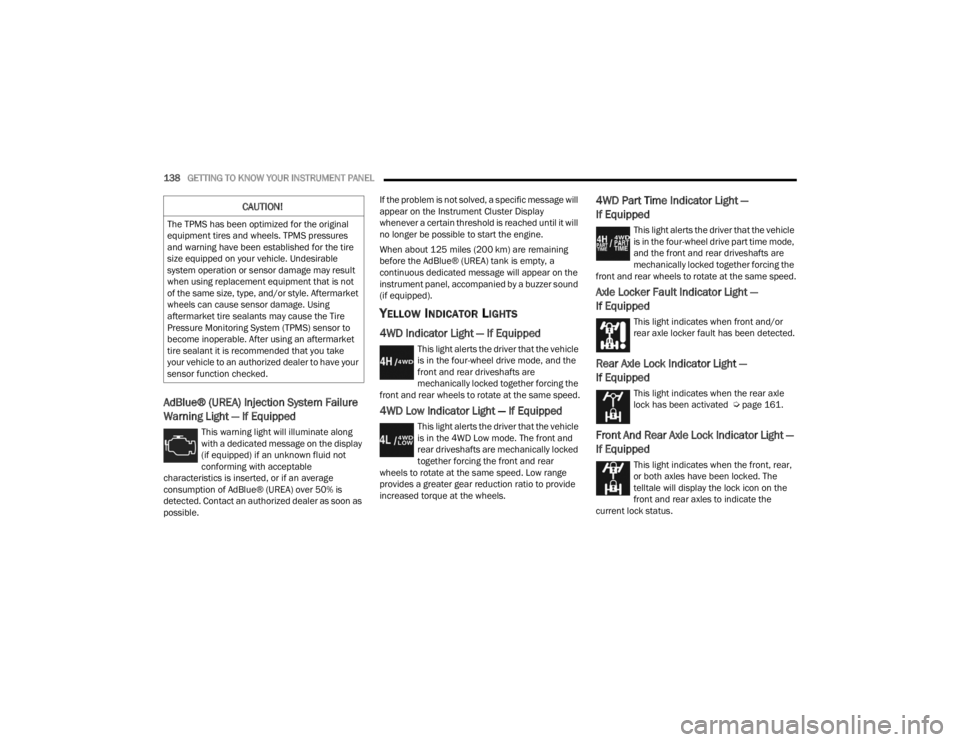
AdBlue® (UREA) Injection System Failure
Warning Light — If Equipped
This warning light will illuminate along
with a dedicated message on the display
(if equipped) if an unknown fluid not
conforming with acceptable
characteristics is inserted, or if an average
consumption of AdBlue® (UREA) over 50% is
detected. Contact an authorized dealer as soon as
possible. If the problem is not solved, a specific message will
appear on the Instrument Cluster Display
whenever a certain threshold is reached until it will
no longer be possible to start the engine.
When about 125 miles (200 km) are remaining
before the AdBlue® (UREA) tank is empty, a
continuous dedicated message will appear on the
instrument panel, accompanied by a buzzer sound
(if equipped).
YELLOW INDICATOR LIGHTS
4WD Indicator Light — If Equipped
This light alerts the driver that the vehicle
is in the four-wheel drive mode, and the
front and rear driveshafts are
mechanically locked together forcing the
front and rear wheels to rotate at the same speed.
4WD Low Indicator Light — If Equipped
This light alerts the driver that the vehicle
is in the 4WD Low mode. The front and
rear driveshafts are mechanically locked
together forcing the front and rear
wheels to rotate at the same speed. Low range
provides a greater gear reduction ratio to provide
increased torque at the wheels.
4WD Part Time Indicator Light —
If Equipped
This light alerts the driver that the vehicle
is in the four-wheel drive part time mode,
and the front and rear driveshafts are
mechanically locked together forcing the
front and rear wheels to rotate at the same speed.
Axle Locker Fault Indicator Light —
If Equipped
This light indicates when front and/or
rear axle locker fault has been detected.
Rear Axle Lock Indicator Light —
If Equipped
This light indicates when the rear axle
lock has been activated Ú page 161.
Front And Rear Axle Lock Indicator Light —
If Equipped
This light indicates when the front, rear,
or both axles have been locked. The
telltale will display the lock icon on the
front and rear axles to indicate the
current lock status.
CAUTION!
The TPMS has been optimized for the original
equipment tires and wheels. TPMS pressures
and warning have been established for the tire
size equipped on your vehicle. Undesirable
system operation or sensor damage may result
when using replacement equipment that is not
of the same size, type, and/or style. Aftermarket
wheels can cause sensor damage. Using
aftermarket tire sealants may cause the Tire
Pressure Monitoring System (TPMS) sensor to
become inoperable. After using an aftermarket
tire sealant it is recommended that you take
your vehicle to an authorized dealer to have your
sensor function checked.
23_JT_OM_EN_USC_t.book Page 138
Page 141 of 448
GETTING TO KNOW YOUR INSTRUMENT PANEL139
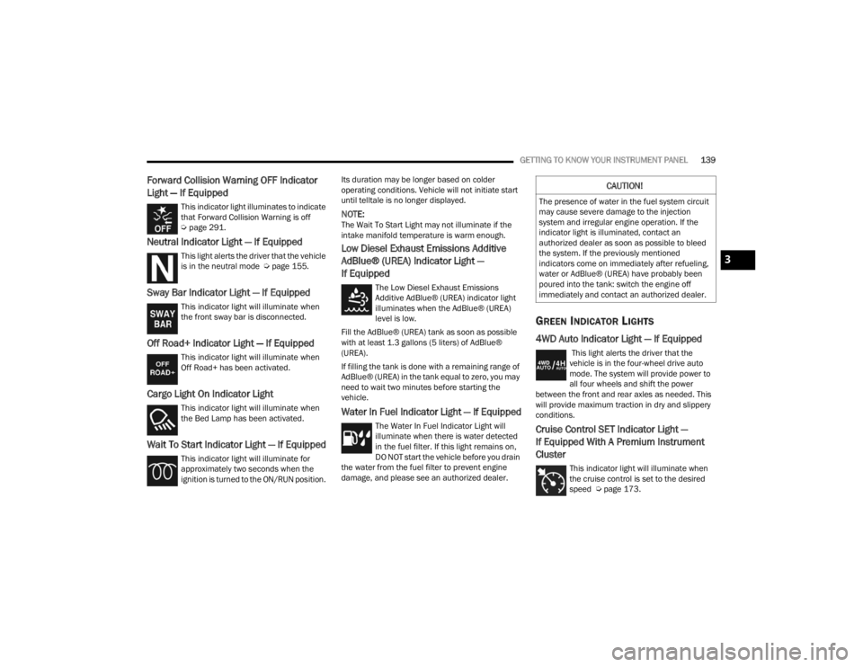
Forward Collision Warning OFF Indicator
Light — If Equipped
This indicator light illuminates to indicate
that Forward Collision Warning is off
Úpage 291.
Neutral Indicator Light — If Equipped
This light alerts the driver that the vehicle
is in the neutral mode Ú page 155.
Sway Bar Indicator Light — If Equipped
This indicator light will illuminate when
the front sway bar is disconnected.
Off Road+ Indicator Light — If Equipped
This indicator light will illuminate when
Off Road+ has been activated.
Cargo Light On Indicator Light
This indicator light will illuminate when
the Bed Lamp has been activated.
Wait To Start Indicator Light — If Equipped
This indicator light will illuminate for
approximately two seconds when the
ignition is turned to the ON/RUN position. Its duration may be longer based on colder
operating conditions. Vehicle will not initiate start
until telltale is no longer displayed.
NOTE:The Wait To Start Light may not illuminate if the
intake manifold temperature is warm enough.
Low Diesel Exhaust Emissions Additive
AdBlue® (UREA) Indicator Light —
If Equipped
The Low Diesel Exhaust Emissions
Additive AdBlue® (UREA) indicator light
illuminates when the AdBlue® (UREA)
level is low.
Fill the AdBlue® (UREA) tank as soon as possible
with at least 1.3 gallons (5 liters) of AdBlue®
(UREA).
If filling the tank is done with a remaining range of
AdBlue® (UREA) in the tank equal to zero, you may
need to wait two minutes before starting the
vehicle.
Water In Fuel Indicator Light — If Equipped
The Water In Fuel Indicator Light will
illuminate when there is water detected
in the fuel filter. If this light remains on,
DO NOT start the vehicle before you drain
the water from the fuel filter to prevent engine
damage, and please see an authorized dealer.
GREEN INDICATOR LIGHTS
4WD Auto Indicator Light — If Equipped
This light alerts the driver that the
vehicle is in the four-wheel drive auto
mode. The system will provide power to
all four wheels and shift the power
between the front and rear axles as needed. This
will provide maximum traction in dry and slippery
conditions.
Cruise Control SET Indicator Light —
If Equipped With A Premium Instrument
Cluster
This indicator light will illuminate when
the cruise control is set to the desired
speed Ú page 173.
CAUTION!
The presence of water in the fuel system circuit
may cause severe damage to the injection
system and irregular engine operation. If the
indicator light is illuminated, contact an
authorized dealer as soon as possible to bleed
the system. If the previously mentioned
indicators come on immediately after refueling,
water or AdBlue® (UREA) have probably been
poured into the tank: switch the engine off
immediately and contact an authorized dealer.
3
23_JT_OM_EN_USC_t.book Page 139