set clock JEEP GLADIATOR 2023 Owners Manual
[x] Cancel search | Manufacturer: JEEP, Model Year: 2023, Model line: GLADIATOR, Model: JEEP GLADIATOR 2023Pages: 448, PDF Size: 17.37 MB
Page 18 of 448
16GETTING TO KNOW YOUR VEHICLE
To Lock/Unlock The Doors And Tailgate
Push and release the unlock button on the key fob
once to unlock the driver’s door, or twice to unlock
all the doors. To lock all the doors, push the lock
button once.
When the doors are unlocked, the turn signals will
flash and the illuminated entry system will be
activated. When the doors are locked, the turn
signals will flash and the horn will chirp.
NOTE:
All doors can be programmed to unlock on the
first push of the unlock button through
Uconnect Settings Úpage 215.
The mechanical flip key can be used to lock or
unlock the doors, tailgate, glove compartment,
storage compartments (if equipped), and rear
seatbacks.
Key Left Vehicle Feature
If a valid key fob is no longer detected inside the
vehicle while the vehicle’s ignition system is in the
ON/RUN or START position, the message “Key Fob
Has Left The Vehicle” will be shown in the
instrument cluster display along with an interior
chime. An exterior audible and visual alert will also
be activated to warn the driver. The vehicle’s horn will rapidly chirp three times
along with a single flash of the vehicle’s exterior
lights.
NOTE:
The doors have to be open and then closed in
order for the vehicle to check for the presence of
a key fob; the Key Left Vehicle feature will not
activate until all of the doors are closed.
These alerts will not be activated in situations
where the vehicle’s engine is left running with
the key fob inside.
Replacing The Battery In The Key Fob
The recommended replacement battery is
CR2450.
NOTE:
Customers are recommended to use a battery
obtained from Mopar®. Aftermarket coin
battery dimensions may not meet the original
OEM coin battery dimensions.
Perchlorate material — special handling may
apply. See www.dtsc.ca.gov/hazardouswaste/
perchlorate for further information.
Do not touch the battery terminals that are on
the back housing or the printed circuit board.
When a key fob battery is low, a warning will be
indicated on the vehicle’s instrument cluster,
and the fob LED will no longer illuminate with a
button push.
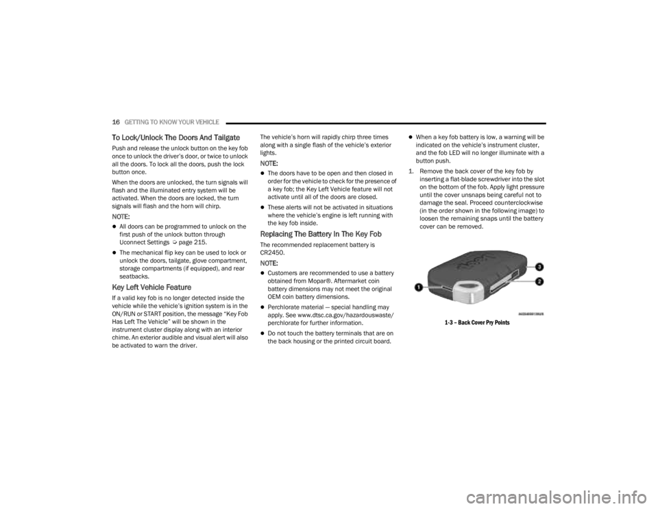
1. Remove the back cover of the key fob by inserting a flat-blade screwdriver into the slot
on the bottom of the fob. Apply light pressure
until the cover unsnaps being careful not to
damage the seal. Proceed counterclockwise
(in the order shown in the following image) to
loosen the remaining snaps until the battery
cover can be removed.
1-3 – Back Cover Pry Points
23_JT_OM_EN_USC_t.book Page 16
Page 60 of 448
58GETTING TO KNOW YOUR VEHICLE
AUTOMATIC HIGH BEAM HEADLAMP
C
ONTROL — IF EQUIPPED
The Automatic High Beam Headlamp Control
system provides increased forward lighting at night
by automatically controlling the high beams
through the use of a camera mounted on the
vehicle’s header. This camera detects vehicle
specific light and automatically switches from high
beams to low beams until the approaching vehicle
is out of view.
NOTE:
The Automatic High Beam Headlamp Control
can be turned on or off by selecting “ON” under
“Auto Dim High Beams” within your Uconnect
Settings Ú page 215, as well as turning the
headlight switch to the AUTO position and
placing the multifunction lever in the high beam
position.
Broken, muddy, or obstructed headlights and
taillights of vehicles in the field of view will
cause headlights to remain on longer (closer to
the vehicle). Also, dirt, film, and other obstruc -
tions on the windshield or camera lens will
cause the system to function improperly.
FLASH-TO-PASS
The Flash-To-Pass feature will illuminate the high
beam headlights temporarily to signal another
vehicle of a passing occurrence. Pull and hold the
Multifunction Lever to activate the Flash-To-Pass
feature. When the lever is released, the
Flash-To-Pass feature will deactivate.
AUTOMATIC HEADLIGHTS — IF EQUIPPED
The Automatic Headlight System will turn the
headlights on or off according to ambient light
levels. To turn the system on, rotate the headlight
switch clockwise to the last detent for automatic
headlight operation. When the system is on, the
headlight time delay feature is also on. This means
the headlights will stay on for up to 90 seconds
(programmable through the Uconnect Settings
Ú
page 215) after you place the ignition into the
OFF position. To turn the automatic system off,
move the headlight switch out of the AUTO position.
NOTE:The engine must be running before the headlights
will come on in the automatic mode.
LIGHTS-ON REMINDER
If the headlights or parking lights are left on after
the ignition is placed in the OFF position, the vehicle
will chime when the driver’s door is opened.
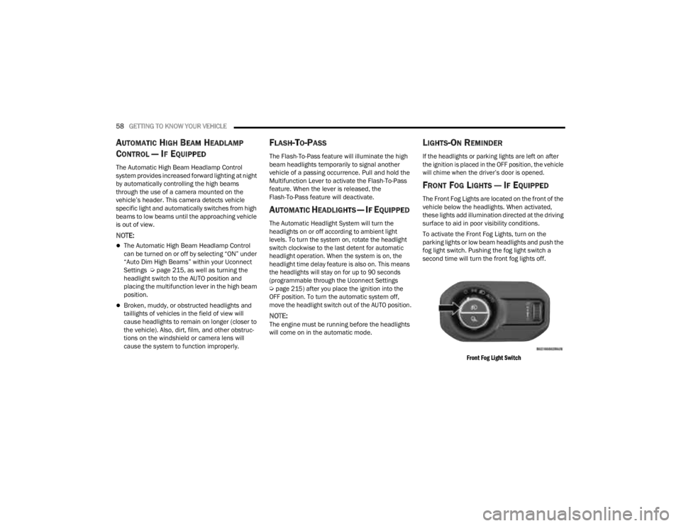
FRONT FOG LIGHTS — IF EQUIPPED
The Front Fog Lights are located on the front of the
vehicle below the headlights. When activated,
these lights add illumination directed at the driving
surface to aid in poor visibility conditions.
To activate the Front Fog Lights, turn on the
parking lights or low beam headlights and push the
fog light switch. Pushing the fog light switch a
second time will turn the front fog lights off.
Front Fog Light Switch
23_JT_OM_EN_USC_t.book Page 58
Page 66 of 448
64GETTING TO KNOW YOUR VEHICLE
Blower Control
Blower Control regulates the amount of
air forced through the Climate Control
system. There are seven blower speeds
available. Adjusting the blower will cause
automatic mode to switch to manual operation.
The speeds can be selected using either the
blower control knob on the faceplate or the
buttons on the touchscreen.
Faceplate
The blower speed increases as you turn the blower
control knob clockwise from the lowest blower
setting. The blower speed decreases as you turn
the blower control knob counterclockwise.
Touchscreen
Use the small blower icon to reduce the blower
setting and the large blower icon to increase the
blower setting. Blower can also be selected by
pressing the blower bar area between the icons.
Mode Control
Turn the mode control knob or press one
of the Mode buttons on the touchscreen
to adjust airflow distribution. The airflow
distribution mode can be adjusted so air
comes from the instrument panel outlets, floor
outlets, defrost outlets and demist outlets.
Panel Mode
Air comes from the outlets in the
instrument panel. Each of these outlets
can be individually adjusted to direct the
flow of air. The air vanes of the center
outlets and outboard outlets can be moved up and
down or side to side to regulate airflow direction.
There is a shut-off wheel located below the air
vanes to shut off or adjust the amount of airflow
from these outlets.
Bi-Level Mode
Air comes from the instrument panel
outlets and floor outlets. A slight amount
of air is directed through the defrost and
side window demister outlets.
NOTE:Bi-Level mode is designed under comfort condi -
tions to provide cooler air out of the panel outlets
and warmer air from the floor outlets.
Floor Mode
Air comes from the floor outlets. A slight
amount of air is directed through the
defrost and side window demister
outlets.
Mix Mode
Air is directed through the floor, defrost,
and side window demister outlets. This
setting works best in cold or snowy
conditions that require extra heat to the
windshield. This setting is good for maintaining
comfort while reducing moisture on the
windshield.
Climate Control OFF Button
Press and release this button on the
touchscreen, or push and release the
button on the blower knob to turn the
Climate Control ON/OFF.
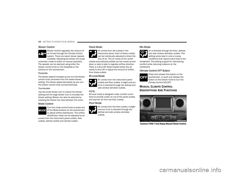
MANUAL CLIMATE CONTROL
D
ESCRIPTIONS AND FUNCTIONS
Uconnect 4 With 7-inch Display Manual Climate Controls
23_JT_OM_EN_USC_t.book Page 64
Page 68 of 448
66GETTING TO KNOW YOUR VEHICLE
Temperature Control
Temperature Control regulates the
temperature of the air forced through the
climate system. The temperature
increases as you turn the temperature
control knob clockwise.
The temperature decreases as you turn
the temperature control knob
counterclockwise. Heater Only
Turning the temperature control knob clockwise
increases the heating temperature and turning the
temperature control knob counterclockwise
decreases the heating temperature.
Blower Control
Blower Control regulates the amount of
air forced through the climate system.
There are seven blower speeds available.
The blower speeds increase as you turn
the blower control knob clockwise from the lowest
blower setting. The blower speed decreases as you
turn the blower control knob counterclockwise.
Mode Control
Turn the mode control knob or press one
of the Mode buttons on the touchscreen
to adjust airflow distribution. The airflow
distribution mode can be adjusted so air
comes from the instrument panel outlets, floor
outlets, defrost outlets and demist outlets.
Panel Mode
Air comes from the outlets in the
instrument panel. Each of these outlets
can be individually adjusted to direct the
flow of air. The air vanes of the center
outlets and outboard outlets can be moved up and
down or side to side to regulate airflow direction.
There is a shut-off wheel located below the air vanes to shut off or adjust the amount of airflow
from these outlets.
Bi-Level Mode
Air comes from the instrument panel
outlets and floor outlets. A slight amount
of air is directed through the defrost and
side window demister outlets.
NOTE:Bi-Level mode is designed under comfort condi
-
tions to provide cooler air out of the panel outlets
and warmer air from the floor outlets.
Floor Mode
Air comes from the floor outlets. A slight
amount of air is directed through the
defrost and side window demister outlets.
Mix Mode
Air is directed through the floor, defrost,
and side window demister outlets. This
setting works best in cold or snowy
conditions that require extra heat to the
windshield. This setting is good for maintaining
comfort while reducing moisture on the
windshield.
Climate Control OFF Button
Press and release this button to turn the
Climate Control ON/OFF.
CAUTION!
Failure to follow these cautions can cause
damage to the heating elements:
Use care when washing the inside of the rear
window. Do not use abrasive window cleaners
on the interior surface of the window. Use a
soft cloth and a mild washing solution, wiping
parallel to the heating elements. Labels can
be peeled off after soaking with warm water.
Do not use scrapers, sharp instruments, or
abrasive window cleaners on the interior
surface of the window.
Keep all objects a safe distance from the
window.
23_JT_OM_EN_USC_t.book Page 66
Page 220 of 448
218MULTIMEDIA
Voice
Clock
When the Voice button is pressed on the touchscreen, the system displays the options related to the vehicle’s Voice Recognition feature.
NOTE:Depending on the vehicle’s options, feature settings may vary.
Setting Name Description
Voice Response Length This setting will change the response length for the Voice Recognition system.
The “Brief” setting provides a shortened audio description from the system.
The “Detailed” setting provides the full audio description from the system.
Show Command List This setting will allow you to turn the Command List on or off. The “Always”
setting will always show the Command List. The “With Help” setting will show
the Command List and provide a brief description of what the command does.
The “Never” setting will turn the Command List off.
When the Clock button is pressed on the touchscreen, the system displays the different options related to the vehicle’s internal clock.
NOTE:Depending on the vehicle’s options, feature settings may vary.
Setting Name
Description
Sync Time With GPS This setting will sync the time to the GPS receiver in the system. The system
will control the time via the GPS location.
Set Time And Format/Time Format This setting will allow you to set the time format (AM/PM). Sync Time With GPS
must be Off for this setting to be available. The “12 hrs” setting will set the
time to a 12-hour format. The “24 hrs” setting will set the time to a 24-hour
format.
23_JT_OM_EN_USC_t.book Page 218
Page 235 of 448
MULTIMEDIA233
Stop use immediately if a problem occurs.
Failure to do so may cause injury or damage to
the product. See an authorized dealer for repair.
Ensure the volume level of the system is set to a
level that still allows you to hear outside traffic
and emergency vehicles.
Safe Usage Of The Uconnect System
The Uconnect system is a sophisticated elec -
tronic device. Do not let young children use the
system.
Permanent hearing loss may occur if you play
your music or sound system at loud volumes.
Exercise caution when setting the volume on the
system.
Keep drinks, rain and other sources of moisture
away from the system. Besides damage to the
system, moisture can cause electric shocks as
with any electronic device.
NOTE:Many features of this system are speed
dependent. For your own safety, it is not possible to
use some of the touchscreen features while the
vehicle is in motion.
Care And Maintenance
Do not press the touchscreen with any hard or
sharp objects (pen, USB stick, jewelry, etc.),
which could scratch the surface.
Do not spray any liquid or chemicals directly on
the screen! Use a clean and dry microfiber lens
cleaning cloth in order to clean the touchscreen.
If necessary, use a lint-free cloth dampened
with a cleaning solution, such as isopropyl
alcohol or an isopropyl alcohol and water solu -
tion ratio of 50:50. Be sure to follow the solvent
manufacturer's precautions and directions
Ú page 432.
UCONNECT MODES
STEERING WHEEL AUDIO CONTROLS
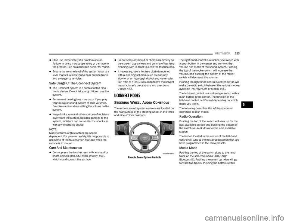
The remote sound system controls are located on
the rear surface of the steering wheel at the three
and nine o’clock positions.
Remote Sound System Controls
The right-hand control is a rocker-type switch with
a push button in the center and controls the
volume and mode of the sound system. Pushing
the top of the rocker switch will increase the
volume, and pushing the bottom of the rocker
switch will decrease the volume.
Pushing the right-hand control’s center button will
make the radio switch between the various modes
available (AM/FM/SXM or Media, etc.).
The left-hand control is a rocker-type switch with a
push button in the center. The function of the
left-hand control is different depending on which
mode you are in.
The following describes the left-hand control
operation in each mode:
Radio Operation
Pushing the top of the switch will seek up for the
next available station and pushing the bottom of
the switch will seek down for the next available
station.
The button located in the center of the left-hand
control will tune to the next preset station that you
have programmed in the radio presets.
Media Mode
Pushing the top of the switch skips to the next
track on the selected media (AUX/USB/
Bluetooth®). Pushing the switch up twice will go
forward two tracks. Pushing the bottom switch
5
23_JT_OM_EN_USC_t.book Page 233
Page 236 of 448
234MULTIMEDIA
goes to the beginning of the current track, or the
beginning of the previous track if it is within eight
seconds after the current track begins to play.
Double pressing the bottom button switch will skip
to the previous track if it is after eight seconds into
the current track.
RADIO MODE
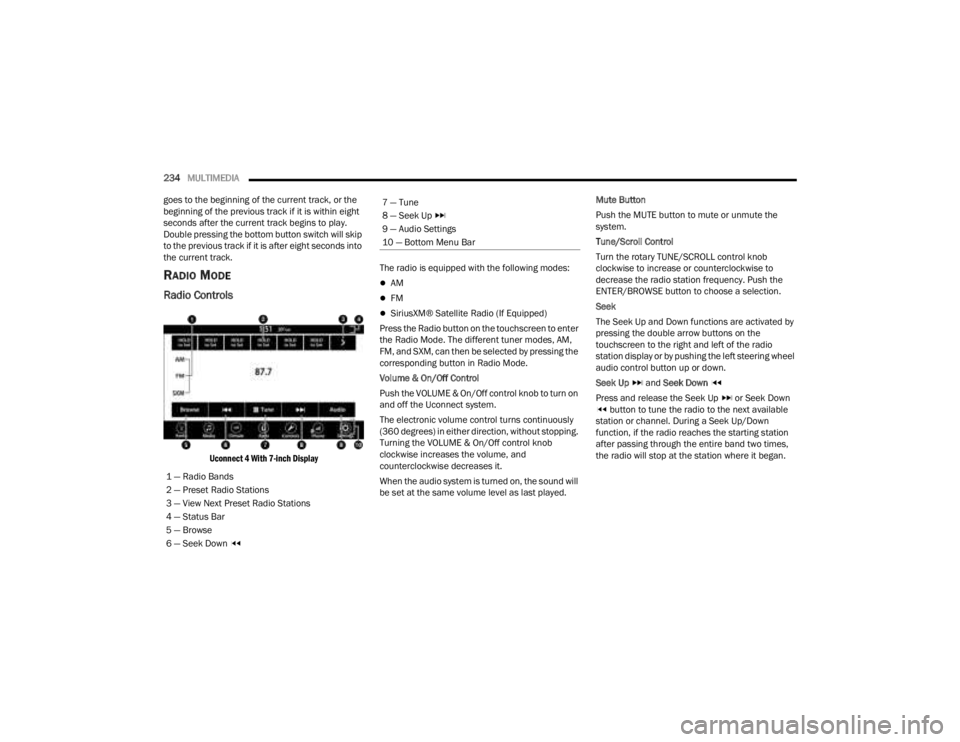
Radio Controls
Uconnect 4 With 7-inch Display
The radio is equipped with the following modes:
AM
FM
SiriusXM® Satellite Radio (If Equipped)
Press the Radio button on the touchscreen to enter
the Radio Mode. The different tuner modes, AM,
FM, and SXM, can then be selected by pressing the
corresponding button in Radio Mode.
Volume & On/Off Control
Push the VOLUME & On/Off control knob to turn on
and off the Uconnect system.
The electronic volume control turns continuously
(360 degrees) in either direction, without stopping.
Turning the VOLUME & On/Off control knob
clockwise increases the volume, and
counterclockwise decreases it.
When the audio system is turned on, the sound will
be set at the same volume level as last played. Mute Button
Push the MUTE button to mute or unmute the
system.
Tune/Scroll Control
Turn the rotary TUNE/SCROLL control knob
clockwise to increase or counterclockwise to
decrease the radio station frequency. Push the
ENTER/BROWSE button to choose a selection.
Seek
The Seek Up and Down functions are activated by
pressing the double arrow buttons on the
touchscreen to the right and left of the radio
station display or by pushing the left steering wheel
audio control button up or down.
Seek Up
and Seek Down
Press and release the Seek Up or Seek Down button to tune the radio to the next available
station or channel. During a Seek Up/Down
function, if the radio reaches the starting station
after passing through the entire band two times,
the radio will stop at the station where it began.
1 — Radio Bands
2 — Preset Radio Stations
3 — View Next Preset Radio Stations
4 — Status Bar
5 — Browse
6 — Seek Down
7 — Tune
8 — Seek Up
9 — Audio Settings
10 — Bottom Menu Bar
23_JT_OM_EN_USC_t.book Page 234
Page 345 of 448
IN CASE OF EMERGENCY343
REINSTALLING THE JACK AND TOOLS
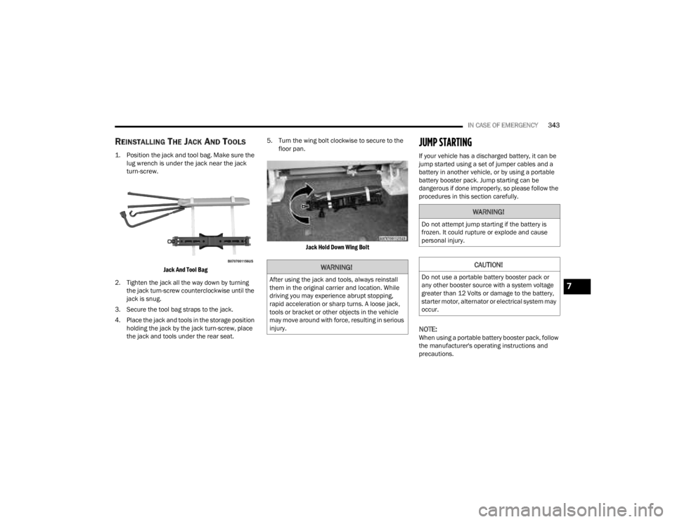
1. Position the jack and tool bag. Make sure the
lug wrench is under the jack near the jack
turn-screw.
Jack And Tool Bag
2. Tighten the jack all the way down by turning the jack turn-screw counterclockwise until the
jack is snug.
3. Secure the tool bag straps to the jack.
4. Place the jack and tools in the storage position holding the jack by the jack turn-screw, place
the jack and tools under the rear seat. 5. Turn the wing bolt clockwise to secure to the
floor pan.
Jack Hold Down Wing Bolt
JUMP STARTING
If your vehicle has a discharged battery, it can be
jump started using a set of jumper cables and a
battery in another vehicle, or by using a portable
battery booster pack. Jump starting can be
dangerous if done improperly, so please follow the
procedures in this section carefully.
NOTE:When using a portable battery booster pack, follow
the manufacturer's operating instructions and
precautions.
WARNING!
After using the jack and tools, always reinstall
them in the original carrier and location. While
driving you may experience abrupt stopping,
rapid acceleration or sharp turns. A loose jack,
tools or bracket or other objects in the vehicle
may move around with force, resulting in serious
injury.
WARNING!
Do not attempt jump starting if the battery is
frozen. It could rupture or explode and cause
personal injury.
CAUTION!
Do not use a portable battery booster pack or
any other booster source with a system voltage
greater than 12 Volts or damage to the battery,
starter motor, alternator or electrical system may
occur.
7
23_JT_OM_EN_USC_t.book Page 343